Table of Contents
Advertisement
Quick Links
Advertisement
Table of Contents

Related Manuals for Fluke Calibration 5322A


Summary of Contents for Fluke Calibration 5322A
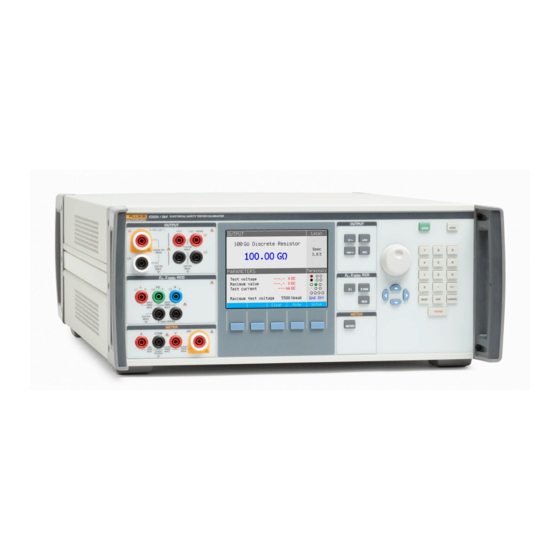
- Page 1 5322A Multifunction Electrical Tester Calibrator Calibration Manual March 2022 © 2022 Fluke Corporation. All rights reserved. Specifications are subject to change without notice. All product names are trademarks of their respective companies.
- Page 2 LIMITED WARRANTY AND LIMITATION OF LIABILITY Each Fluke product is warranted to be free from defects in material and workmanship under normal use and service. The warranty period is one year and begins on the date of shipment. Parts, product repairs, and services are warranted for 90 days.
-
Page 3: Table Of Contents
Table of Contents Title Page Introduction ....................Contact Fluke .................... Service Information ................... Safety Information ..................Specifications .................... Theory of Operation .................. Low-Resistance Source (LVR Board)..........High-Resistance Source (HVR/HVRB Board) ........Ground Bond Resistance Source (REL Board) ........AC/DC Voltage Adjustment (VCAL + AMP Board) ......AC/DC Multimeter (MER Board)............ - Page 4 5322A Calibration Manual High Resistance Source Meters 5 kV Adjustment (Optional)....36 Voltmeter adjustment HVR V01-HVR V09 ........36 Ammeter Adjustment HVR I01 ............. 38 10 GW Input Resistance Calibration ..........39 High Resistance Source Meters 1.5 kV Adjustment ......39 Voltmeter Adjustment HVR V01-HVR V04 ........
- Page 5 Multifunction Electrical Tester Calibrator Table of Contents Clean the Air Filter ................93 Clean the Exterior ................94 Electrical Parts ..................94...
- Page 6 5322A Calibration Manual...
-
Page 7: Introduction
Active Loop Compensation Where necessary, the text is specific to each of these Products. Otherwise, the manual applies to all of the Products. Throughout the manual, all varieties of the 5322A are referred to as the Product or Calibrator. -
Page 8: Safety Information
Specifications Safety Specifications are in the Safety Specifications section of the Safety Information document. Complete Product specifications are at www.flukecal.com. See the 5322A Product Specifications. Theory of Operation The Product is a Multifunction Electrical Tester Calibrator that covers a wide range of calibrations of devices under test (DUT). - Page 9 Multifunction Electrical Tester Calibrator Theory of Operation Electronic circuits located on the internal printed circuit boards (PCB) include: • Ground bond resistance decade, RCD and Loop/Line impedance circuits • Multimeter block, RCD, Loop/Line impedance and Leakage current control processor. • Floating voltmeter and ammeter •...
-
Page 10: Low-Resistance Source (Lvr Board)
5322A Calibration Manual Low-Resistance Source (LVR Board) A programmable, parallel-resistance decade with partial resistors values in nominal weight 1:2:4:4 forms a low-resistance source. Relays switch the resistors. The main CPU controls the switching process. The total range of partial resistors covers 100 m Ω to 16 M Ω . A one-range internal voltmeter senses the low-resistance decade applied test voltage. -
Page 11: Ground Bond Resistance Source (Rel Board)
Multifunction Electrical Tester Calibrator Theory of Operation Ground Bond Resistance Source (REL Board) A programmable resistance box that contains 16 fix values in range 25 m Ω to 1.8 k Ω forms a ground bond resistance source. Relays switch the resistors. The main CPU controls the switching. -
Page 12: Ac/Dc Multimeter (Mer Board)
5322A Calibration Manual Figure 5. AC/DC Voltage Calibrator Principle Differential Feedback D/A Converter Amplifier Circuit Crystal Generator 30V amplifier Oscillator AMP board AC/DC Multimeter (MER Board) The on-board ac/dc multimeter simultaneously measures any external voltage in range to 5000 Vrms and current to 30 Arms. Both voltage and current channels have a range amplifier and selectable ac/dc converter. -
Page 13: Loop/Line Impedance (Rel+Comp Board)
Multifunction Electrical Tester Calibrator Theory of Operation The multimeter is on the MER board. The board floats up to 2000 V above PE potential. The Meter function (M) has these sub-functions. Push the Mode softkey to select each sub- function: •... -
Page 14: Rcd Function (Rel
5322A Calibration Manual RCD function (REL+IFC board) The RCD function contains two fast electronic switches, controlled from the CPU. Control of the switches comes from the sampling ammeter measurement. The ammeter is inserted at the PE wire and it senses the trip current caused by the DUT. When the fault current reaches a preset value, the CPU unit switches off both of the electronic switches after the preset trip time. -
Page 15: Rcd In Pat Function (Rcd Board)
Multifunction Electrical Tester Calibrator Theory of Operation RCD in PAT Function (RCD Board) Use this function to adjust PAT testers that have an RCD function that measures trip time in portable RCD breakers such as extension cords. In this function, the Product does not supply power line voltage. -
Page 16: Passive And Differential Leakage Current (Ifc+Lvr Board)
5322A Calibration Manual Passive and Differential Leakage Current (IFC+LVR Board) In a passive and differential leakage current function, the sampling ammeter senses leakage current that comes from the DUT from the H terminal to L terminal. According to its value, the ammeter sets such a value on the resistance decade. -
Page 17: Active Leakage Current (Ifc+Lvr Board, Optional)
Multifunction Electrical Tester Calibrator Theory of Operation Active Leakage Current (IFC+LVR Board, Optional) In active leakage current mode, the Product generates ac current with an internal ac calibrator as the source of current. A sampling ammeter sets this value in low-resistance decade, the output current equals the preset current value. -
Page 18: Calibration
1. Substitute equipment must meet the same minimum use specifications. Table 1. Required Equipment Item Equipment Fluke 8588A or equivalent with 4 test leads Reference Multimeter Quadtech MegaΩmeter 1653 or similar, with Megohmeter 3 test leads Fluke Calibration 5522A Multi-product Calibrator... -
Page 19: Adjustment Principles
Multifunction Electrical Tester Calibrator Calibration Adjustment Principles Adjust all or only selected functions of the Product at each listed adjustment point. Make adjustments in the order defined in the calibration menu. If the menu shows a selected item (for example METER) it is not necessary to adjust all ranges defined by the calibration algorithm. -
Page 20: Access The Calibration Procedure
5322A Calibration Manual • RCD Trip Current Calibration data of ammeter and line voltage meter in the RCD function. • Leakage Current Calibration data of internal leakage current ammeter. • HV Probes Calibration constants for 10 kV and 40 kV external probes. -
Page 21: Types Of Adjustment Points
Multifunction Electrical Tester Calibrator Calibration For example, if you select Ground Bond Resistance from the calibration menu, the Ground Bond Resistance screen shows the screen in Figure 13. The screen shows GBR R00 highlighted. To choose this parameter, push the Select softkey. Figure 13. - Page 22 5322A Calibration Manual For example, in Figure 14, the Ground Bond Resistance screen shows the resistance segment to adjust with this syntax: • ground bond resistance decade • ordinal number of the resistance segment • 100 mΩ nominal value of calibrated resistance segment •...
- Page 23 Multifunction Electrical Tester Calibrator Calibration For example, in Figure 15, the display indicates the High Resistance Source Voltmeter segment to be adjusted in this syntax: • High voltage decade • Voltmeter senses voltage on the decade, range 01 • Measured value Life reading of the High Resistance Voltmeter •...
- Page 24 5322A Calibration Manual For example, in Figure 16, the display shows the DC Multimeter range, 100V, adjustment of the zero point (dc offset) in this syntax: • Range 100V low (0 V) DC range 100 V, nominal calibration point 1000 mV •...
- Page 25 Multifunction Electrical Tester Calibrator Calibration For example, in Figure 17, the display identifies the active resistance segment in this syntax: • Range 30V high (+30 V) DC voltage range 30 V of internal voltage calibrator, nominal value +30 V dc •...
-
Page 26: Terminate The Calibration Process
5322A Calibration Manual For example, Figure 18 shows a 10 kV HV Probes screen. Figure 18. 10 kV Probe Screen Identification of the active resistance segment shows in this syntax: 10kV probe ratio Dividing constant K for 10 kV probe 1000.0... -
Page 27: Adjustment Procedures
Use the 8588A or similar multimeter for these procedures. To adjust the Product: 1. Make the connections shown in Figure Figure 19. Ground Bond Resistance Adjustment Connections Fluke 5322A Fluke 8588A 2-wire Mode Fluke 5322A Fluke 8588A 4-wire Mode... - Page 28 5322A Calibration Manual 2. Push the Product Setup softkey. 3. Select Calibration and push the Select softkey. 4. From the calibration menu, select Ground Bond Resistance 2W or Ground Bond Resistance 4W and push the Select softkey. 5. The list of calibration points shows in this format:...
- Page 29 Multifunction Electrical Tester Calibrator Adjustment Procedures Table 2. 2-Wire (2W) Adjustment Points (cont.) Nominal Required Resistance Position Accuracy of Lower Limit Upper Limit Value Adjustment 170 Ω GBR2W -10 % +10 % ±200 m Ω 470 Ω GBR2W -10 % +10 % ±500 m Ω...
-
Page 30: Low-Resistance Source Adjustment
1. Make the 4-wire connections shown in Figure Figure 20. Low-Resistance Source Adjustment Connections Fluke 8588A Fluke 5322A 2. Set the multimeter to the 4W or 4W TRUE function. 3. Push the Setup softkey on the Product. 4. Select Calibration and confirm with the Select softkey. - Page 31 Multifunction Electrical Tester Calibrator Adjustment Procedures 9. Confirm the value with the Write softkey. If there is no need to change value, push the Exit softkey to keep the original value. 10. Go through all positions in the list and make an adjustment for each resistor. 11.
-
Page 32: High Resistance Source Adjustment 5 Kv (Optional)
5322A Calibration Manual Table 4. Low Resistance Source Adjustment Points (cont.) Nominal Required Adjustment Position Calibration Accuracy of Lower Limit Upper Limit Point Value Adjustment LVR24 65 k Ω 70 000 Ω 0.05 % -10 % +10 % LVR25 100 k Ω... - Page 33 1. Connect the Product to the 1653 (for values above 10 M Ω ) or to the 8588A (for values <10 M Ω ): Figure 21. High Resistance Source Adjustment for ≥ 10 Ω M Connections Fluke 5322A 1653 INPUT Hi...
- Page 34 5322A Calibration Manual 2. Push the Setup softkey on the Product. 3. Select Calibration and confirm with the Select softkey. 4. From the calibration menu, highlight High Resistance Source and push The list of adjustment points appears in format: HVR Rxx nominal resistance value...
-
Page 35: High Resistance Source Adjustment 1.5 Kv
Multifunction Electrical Tester Calibrator Adjustment Procedures Table 5. High Resistance Source Adjustment Points (cont.) 20.0 M Ω HVR12 0.1 % -10 % +10 % 40.0 M Ω HVR13 0.1 % -10 % +10 % 78.0 M Ω HVR14 0.1 % -10 % +10 % 150 M Ω... - Page 36 5322A Calibration Manual 5. Select the first position with a nominal value of 10 k Ω . 6. Measure its value with a standard meter. 7. Write down the new value. Use the cursor keys and the numerical keypad to enter the new value.
- Page 37 Multifunction Electrical Tester Calibrator Adjustment Procedures Table 6. High Resistance Source Adjustment for 1.5 kV Adjustment Points Required Nominal Value Position Accuracy of Lower Limit Upper Limit Adjustment 10 k Ω HVR00 0.02 % -5 % +5 % 18 k Ω HVR01 0.02 % -5 %...
-
Page 38: Ground Bond Resistance Meters Adjustment
To adjust the Product, see Figure 1. Connect the current output of the 5322A to the ZGND PE and N terminals. Figure 23. Ground Resistance Souce Meters Adjustment Connection 1 Fluke 5322A Fluke 5522A... - Page 39 Multifunction Electrical Tester Calibrator Adjustment Procedures 8. Connect the voltage output of the 5522A to the ZGND PE and N terminals. See Figure Figure 24. Ground Resistance Meters Adjustment Connection 2 Fluke 5322A Fluke 5522A 5522A CALIBRATOR STBY 9. Select GBR V01 Test Voltage 23 VacL (Open) and push the Select softkey.
-
Page 40: Low Resistance Source Meters Adjustment
Low Resistance Source Meters Adjustment To adjust the low resistance meters, see Figure 1. Connect the 5522A to the OUTPUT HI Ω HI and LO terminals. Figure 25. Low Resistance Source Meters Adjustment Connections 1 Fluke 5322A Fluke 5522A 5522A CALIBRATOR STBY 2. - Page 41 To set the required constants to adjust the test voltage auxiliary voltmeter: 1. Connect the 5522A to the OUTPUT HI Ω HI and LO terminals of the Product, see Figure Figure 26. Low Resistance Source Meters Adjustment Connections 2 Fluke 5322A Fluke 5522A 5522A CALIBRATOR STBY 2.
-
Page 42: High Resistance Source Meters 5 Kv Adjustment (Optional)
5322A Calibration Manual High Resistance Source Meters 5 kV Adjustment (Optional) Adjustment of High Resistance Source Meters 5 kV consists of these steps: 1. Voltmeter adjustment HVR V01-HVR V09 2. Ammeter adjustment HVR I01 3. 10 G Ω Input resistance calibration Voltmeter adjustment HVR V01-HVR V09 Use an external high voltage dc source to adjust the internal voltmeter of the Product. - Page 43 Multifunction Electrical Tester Calibrator Adjustment Procedures Figure 27. High Resistance Source Meters 5 kV Adjustment Connections High Voltage Source Fluke 5322A Precision HV Divider Fluke 8508A Digital Multimeter...
-
Page 44: Ammeter Adjustment Hvr I01
5322A Calibration Manual Table 7. Adjustment - High Resistance Meters 5 kV Adjustment Adjustment Point Output Voltage Calibration Constant Resistance Condition HVR V01 0.0 V dc Offset 1 M Ω HVR V01 1100 V dc 1 M Ω Slope HVR V02 0.0 V dc... -
Page 45: Gw Input Resistance Calibration
Multifunction Electrical Tester Calibrator Adjustment Procedures Figure 28. High Resistance Meters 5 kV Adjustment Connections Fluke 5322A Fluke 5522A 5522A CALIBRATOR STBY 10 G Ω Input Resistance Calibration The internal voltmeter adjustment of the 5 kV high resistance source procedure requests a measurement of one 10 G Ω... -
Page 46: Voltmeter Adjustment Hvr V01-Hvr V04
3. Select HVR V01 Offset 1000Vdc (>1M) and push the Select softkey. 4. Set the output voltage at 0.0 V dc on the 5322A and switch the output terminals ON. 5. Use the rotary knob or cursor keys to set the Product to 0.0 V. -
Page 47: Ammeter Adjustment Hvr I01
This procedure requires you to set one constant at 20 mA dc to adjust the test voltage auxiliary voltmeter. 1. Connect the Product to the OUTPUT HI Ω HI and LO terminals, see Figure Figure 30. High Resistance Meters 1.5 kV Adjustment Connections 2 Fluke 5322A Fluke 5522A 5522A CALIBRATOR STBY 2. -
Page 48: Dc Voltage Calibrator Adjustment (Optional)
Figure 1. Connect a standard multimeter to the Product output terminals. Figure 31. DC Voltage Adjustment Connections Fluke 5322A Fluke 8588A 2. On the Product, from the Setup menu, set the grounding mode to GND ON. 3. Set the standard multimeter to the most accurate dc voltage mode. -
Page 49: Ac Voltage Calibrator Adjustment (Optional)
AC Voltage Calibrator Adjustment (Optional) Adjustment of the ac voltage calibrator requires adjustment of these ranges: 0.3 V, 3 V, 30 V, 150 V, 300 V, and 600 V. Each range has two adjustment points. Fluke Calibration recommends 55 Hz. - Page 50 5322A Calibration Manual Table 9. AC Voltage Calibrator Adjustment Points Nominal Voltage Required Accuracy of Adjustment Point Frequency Range Adjustment 0.3 V ac 0.03 V ac low 55 Hz 0.03 % 0.3 V ac 0.3 V ac high 55 Hz 0.03 %...
-
Page 51: Dc Multimeter Adjustment
DC Ranges for 10 V, 100 V, 1000 V Calibration To adjust these dc ranges: 1. Connect 5522A to the Product output terminals, see Figure Figure 32. DC Calibration Connections Fluke 5322A Fluke 5522A 5522A CALIBRATOR STBY 2. Set the 5522A to V dc mode. -
Page 52: Dc Range 5000 V Adjustment
5322A Calibration Manual 10. Go through all of the voltage adjustment points for ranges 10 V, 100 V, and 1000 V. Nominal adjustment voltage is noted in parenthesis. This completes this part of the adjustment. DC Range 5000 V Adjustment... - Page 53 Multifunction Electrical Tester Calibrator Adjustment Procedures This completes this part of the adjustment. Figure 33. DC Multimeter Adjustment Connections High Voltage Source Fluke 5322A Precision HV Divider Fluke 8508A Digital Multimeter...
-
Page 54: Dc Current Ranges 0.3 A, 3 A, 30 A Adjustment
To adjust these dc current ranges: 1. Change the mode on the 5522A to DCI and connect it to the Product output terminals, see Figure Figure 34. DC Current 0.3A, 3 A, 30A Adjustment Connections Fluke 5322A Fluke 5522A 5522A CALIBRATOR STBY 2. -
Page 55: Ac Multimeter Adjustment
0.05 % 30 A dc high +20 A 0.05 % AC Multimeter Adjustment The adjustment procedure contains voltmeter adjustments in 3 ranges and ammeter adjustment in 3 ranges. Fluke Calibration recommends 55 Hz. For these procedures and see Table 11 Figure... -
Page 56: Ac Ranges 10 V, 100 V, 1000 V Adjustment
AC Ranges 10 V, 100 V, 1000 V Adjustment To adjust these ac ranges: 1. Connect the 5522A or similar to the Product output terminals, see Figure Figure 35. AC Ranges 10 V, 100 V, and 1000 V Adjustment Connections Fluke 5322A Fluke 5522A 5522A CALIBRATOR STBY 2. -
Page 57: Ac Range 5000 V Adjustment
Multifunction Electrical Tester Calibrator Adjustment Procedures AC Range 5000 V Adjustment To make this adjustment, see Figure 1. Connect the high voltage source to the HV and COM terminals of the Product. 2. Connect the high voltage probe input parallel to the high voltage source output terminals. 3. -
Page 58: Ac Current Ranges 0.3 A, 3 A, 30 A Adjustment
5322A Calibration Manual AC Current Ranges 0.3 A, 3 A, 30 A Adjustment Change the mode on the 5522A to ACI. To adjust these ranges, see Figure 1. Connect the 5522A to the Product output terminals. 2. Set the first current point to 300 mA 55 Hz low (30mA) and push the Select softkey. -
Page 59: Rcd Trip Current Adjustment
(30 mA and 150 mA) for RCD in PAT function. The line voltage meter is one range. To adjust the RCD trip current, see Figure 1. Connect the 5522A to the Product. Figure 36. RCD Trip Current Adjustment Connections Fluke 5322A Fluke 5522A 5522A CALIBRATOR STBY 2. - Page 60 5322A Calibration Manual Table 12. RCD Trip Current Adjustment Points Required Nominal Current Position Adjustment Point Frequency Accuracy of Range Adjustment 30 mA 25 mA 55 Hz 0.2 % + 50 μ A 300 mA 250 mA 55 Hz 0.2 %...
- Page 61 Multifunction Electrical Tester Calibrator Adjustment Procedures Figure 37. RCD Trip Current Line Voltage Adjustment Connections 2 Fluke 5322A Fluke 8588A 14. Set the Product to show the same value as on the standard 8588A. 15. Push the Select softkey to save the new adjustment data.
-
Page 62: Leakage Current Adjustment
5322A Calibration Manual Leakage Current Adjustment This process checks the internal rms ammeter. Adjustment is only for the dc signal. To make this adjustment, see Figure 1. Connect the 5522A to the Product. 2. Push the Setup softkey on the Product. -
Page 63: Hv Probes Adjustment
4. Push the Write softkey to save the value. Note The ac/dc difference parameter is mostly created by the mechanical design of the probes. Fluke Calibration recommends to not change the original constant, if a new constant is not known with uncertainty better than 0.1 %. Note The dc divider coefficient is created by a number that represents 1/p, where p is probe dividing ratio. -
Page 64: High Resistance Multiplier Adjustment
5322A Calibration Manual High Resistance Multiplier Adjustment The calibration process writes and saves these new constants. R multiplier R1 xxxx.x (M Ω ) Input resistor value measured between adapter INPUT HI terminal front panel – LO terminal rear panel R multiplier R2 xxx.x (k Ω... - Page 65 Multifunction Electrical Tester Calibrator Adjustment Procedures Table 14. DC HIPOT Leakage Current Adjustment Points Nominal Current Required Accuracy of Position Adjustment Point Range Adjustment Range 300 μ A low 0.0 mA 0.05 % (0 μ A) 0.3 mA dc Range 300 μ A high 0.25 mA 0.05 % (+300 μ...
-
Page 66: Ac Hipot Leakage Current Adjustment
5322A Calibration Manual AC HIPOT Leakage Current Adjustment Adjust the HIPOT Leakage Current ammeter with the front panel keyboard. Adjustment is done on the ac signal. To make this adjustment, see Figure 1. Connect the 5522A to the Product output terminals. -
Page 67: Hipot Ripple Adjustment
Multifunction Electrical Tester Calibrator Adjustment Procedures This completes this part of the adjustment. HIPOT Ripple Adjustment HIPOT Ripple adjustment enables adjustment of the meters used for the ripple coefficient measurement. Adjustment is done on the ac signal. To make this adjustment, see Figure 1. -
Page 68: Verification
Required Instrument Recommended Model Digital Multimeter Fluke Calibration 8588A or similar model Teraohmmeter Quadratech 1865 Multi-product Calibrator Fluke Calibration 5502A, 5522A or similar model HIPOT Tester Chroma 19052 Counter Keysight 53131A or equivalent 10 kV Divider 5320A/5322A Accessory Product Configuration Test the Product from the front panel terminals. - Page 69 Multifunction Electrical Tester Calibrator Verification 5 kV and 1.5 kV High Resistance Source • Resistance • 100 G Ω value • OPEN resistance • SHORT resistance • 10 m Ω value • Test voltage • Resistance multiplier Voltage Calibrator • AC/DC voltage •...
-
Page 70: Conditions
5322A Calibration Manual Conditions The Fluke Calibration recommended measure points are in Verification Tables. 1. Connect the Product to the mains and leave it switched on for at least 1 hour in a laboratory at 23±1 ° C. 2. Push the Setup softkey on the Product. - Page 71 Select the Z GND function on the Product. Push the Mode softkey and select OPEN. c. Push d. The measured resistance reads >100 k Ω . Figure 38. Ground Bond Resistance and Loop/Line Resistance Value Connections Fluke 5322A Fluke 8588A 2-wire Mode Fluke 5322A...
-
Page 72: Low Resistance Source Verification
5322A Calibration Manual Low Resistance Source Verification Follow the subsequent steps to verify the low resistance source functions. 1. Two-wire low resistance source test: a. Connect the 8588A to the low resistance source output terminals LO Ω HI and LO. Use a four-wire connection and set the 8588A to four-wire measurement. -
Page 73: Kv And 1.5 Kv High Resistance Source
Multifunction Electrical Tester Calibrator Verification 4. SHORT Four-wire Low resistance source test: a. Connect the 8588A +I and -I terminals to the Low resistance source output terminals LOΩ HI and LO. Connect the 8588A +Ω SENSE and -Ω SENSE terminals to the Low resistance source output terminals LOΩ-SENSE HI and LO. - Page 74 5322A Calibration Manual Measure the Product resistance in points 2 GΩ and higher. Compare the measurement on the Product with the limits in Table 2. 100 GΩ test: a. Select the HIΩ function on the Product. Push the Mode softkey and select 100 GΩ.
- Page 75 Compare the1865 with the limits in Table Note Fluke Calibration recommends shielded test leads to avoid the influence of noise. The indication settles depending on the set resistance value and ambient conditions. It can last several minutes under poor conditions.
-
Page 76: Voltage Calibrator
5322A Calibration Manual Voltage Calibrator Follow these steps to verify the voltage calibrator functions. 1. Voltage calibrator test: a. On the Product, select the dc voltage calibrator function. b. Connect the 5522A to the appropriate output terminals of the Product and select the dc voltage function. -
Page 77: Leakage Current
Multifunction Electrical Tester Calibrator Verification Leakage Current Follow these steps to verify leakage current functions. 1. Passive leakage current test: a. Select Calibration>Leakage current. b. Connect the 5522A current output terminals to the HI, LO input terminals of the Product. Select the ac current function on the 5522A and set the frequency to 55 Hz. c. -
Page 78: Rcd Function
Select Setup>Calibration>Trip time position. Set the trip time to value 1000 ms. Figure 39. RCD Verification Connections Fluke 5522A 5522A CALIBRATOR Fluke 5322A STBY Counter R=1-10 kOhm c. Set 5 V dc on the 5522A and turn the output ON. -
Page 79: Meter
Multifunction Electrical Tester Calibrator Verification e. Use the numerical keypad, cursor keys, or rotary knob to set the time interval on Product display in ms. Figure 40. Trip Time Verification Screen If the counter does not indicate 0 ms, reset the counter display. g. - Page 80 5322A Calibration Manual 3. DC/AC multimeter phase test: a. Connect the 5522A current output terminals to A and COM terminals on the Product. b. Connect the 5522A voltage output terminals to V and COM terminals on the Product. c. Set frequency and output voltage as in Table d.
-
Page 81: High Voltage Tests
Connect the 19052 output terminals to the HV and COM input terminals of the Product. b. Use a 5 kV test lead from the 5322A accessory on the high voltage side. c. Connect the grounding post on the Resistance multiplier to the Product rear panel grounding post. - Page 82 Connect the 10 kV divider rear panel output terminals to the V and COM input terminals on the Product. Use the 5 kV test lead from 5322A accessory on the high voltage side. Connect the grounding post on the Resistance multiplier to Product rear panel grounding post.
-
Page 83: Verification Tables
Multifunction Electrical Tester Calibrator Verification Verification Tables Use the tables in this section and the previous procedures to verify the Product meets its specifications. Table 20. Two-wire Ground Bond Decade and Loop/Line Decade Test Nominal Value Lower Limit Upper Limit 20 mΩ... - Page 84 5322A Calibration Manual Table 21. Four-wire Ground Bond Decade and Loop/Line Decade Test (cont.) Nominal value Lower limit Upper limit Rcal -45 mΩ Rcal +45 mΩ 17 Ω Rcal -300 mΩ Rcal +300 mΩ 47 Ω Rcal -500 mΩ Rcal +500 mΩ...
- Page 85 Multifunction Electrical Tester Calibrator Verification Table 23. Four-wire Low Resistance Source Nominal value Lower limit Upper limit 9.47 mΩ 09.38 mΩ 9.56 mΩ 100 mΩ 89.7 mΩ 110. 3 mΩ 200 mΩ 189.4 mΩ 210.6 mΩ 400 mΩ 388.8 mΩ 411.
- Page 86 5322A Calibration Manual Table 24. High Resistance Source Standard Lower Limit Upper Limit Output Nominal Value Multimeter Test Voltage 5 kV & 1.5 kV 5 kV & 1.5 kV Terminals Test Method Version Version HI - LO 10 kΩ 8588A 9.98 kΩ...
- Page 87 9 TΩ multiplier 1865 Rcal [1] Use these points only for model 5322A/5 with 5 kV version high resistance source. [2] Use this point only for model 5322A with 1.5 kV version high resistance source. Table 25. DC/AC Voltage Calibrator Frequency...
- Page 88 5322A Calibration Manual Table 25. DC/AC Voltage Calibrator (cont.) Frequency Test Voltage Lower Limit Upper Limit (Hz) 200 V 199.62 V 200.38 V 300 V 299.52 V 300.48 V 400 V 399.42 V 400.58 V 500 V 499.32 V 500.68 V 600 V 599.22 V...
- Page 89 10.032 mA 25 mA 24.923 mA 25.077 mA 28 mA 27.914 mA 28.086 mA Table 27. RCD Trip Current Test Nominal Current 5322A Range Frequency Lower Limit Higher Limit 10 mA RCD I01 9.9 mA 10.1 mA 20 mA RCD I01 19.8 mA...
- Page 90 5322A Calibration Manual Table 29. DC/AC Voltage Multimeter Test Nominal Output Frequency Lower Limit Upper Limit Voltage (Hz) 3.989 4.011 -4 V -4.011 -3.989 8.982 9.019 40 V 39.870 40.130 -40 V -40.130 -39.870 90 V 89.770 90.230 200 V 199.050...
- Page 91 Multifunction Electrical Tester Calibrator Verification Table 30. DC/AC Current Multimeter Test Nominal Output Frequency Lower Limit Upper Limit Voltage (Hz) 0.100 A 0.0997 0.1003 -0.100 A -0.1003 -0.0997 0.200 A 0.19955 0.20045 -0.200 A -0.20045 -0.19955 0.500 A 0.49775 0.50225 0.997 1.003 -1 A...
- Page 92 5322A Calibration Manual Table 31. AC/DC Phase Multimeter Test Nominal Nominal Nominal Frequency Output Lower Limit Upper Limit Output Current Phase Shift (Hz) Voltage 250 mA AC 100 V 0 ° - 0. 1 ° +0.1 ° 2.5 A AC 100 V 0 °...
- Page 93 Multifunction Electrical Tester Calibrator Verification Table 32. DC/AC HIPOT Leakage Current Test (cont.) Nominal Output Frequency Lower Limit Upper Limit Voltage (Hz) 2.5 mA 2.4935 mA 2.5065 mA 10 mA 9.965 mA 10.035 mA 20 mA 19.945 mA 20.055 mA 25 mA 24.935 mA 25.065 mA...
-
Page 94: List Of Error Messages
5322A Calibration Manual List of Error Messages Table 34 for a list of error messages shown by the Product. Table 34. Error Messages Error message Description Remote interface error. A received command generates too much data to fit in the output buffer and the output -430 Deadlocked. - Page 95 Multifunction Electrical Tester Calibrator List of Error Messages Table 34. Error Messages (cont.) Error message Description Compensator Overloaded compensator (high residual impedance, overload measurement current or long measurement time). Compensator Cannot select compensator because residual disabled impedance is >10 Ω . Cont.
-
Page 96: Maintenance
Clean the air filter and external surfaces. • There are no user-serviceable items within the Product. Do not remove the Product covers. For intensive maintenance, tasks such as repair, contact the Fluke Calibration service center. • Calibrate the Product annually. -
Page 97: Clean The Ground Bond Resistance And Loop/Line Impedance Relays
The Ground Bond Resistance and Loop/Line Impedance specifications are based on how often the relays are cleaned. See the 5322A Specifications. If the relay cleaning procedure has not been done within the past 90 days, the Product prompts you to run the procedure at startup with the displayed message: Start the cleaning procedure. -
Page 98: Measurement Input Fuses
5322A Calibration Manual Table 35. Line Power Fuses Line Voltage Selection Fuse Fluke Part No. 115 V W T4L250V (5 x 20 mm) 2743488 230 V W T2L250V (5 x 20 mm) 2743495 Measurement Input Fuses The Amps (A) terminal of the METER input, the HI terminal of the OUPUT terminals, and the L terminal or the RCD terminals are protected by fuses at the rear of the Product. - Page 99 Multifunction Electrical Tester Calibrator Maintenance Clean the Air Filter W Caution Damage from overheating can occur if the area around the fan is restricted, the intake air is too warm, or there is a clogged air filter. Clean the air filter at least every 30 days, or more frequently if the Product is in a dusty environment.
- Page 100 5322A Calibration Manual Clean the Exterior Clean the case, front-panel keys, and lens with a soft cloth, slightly dampened with water or a non-abrasive mild cleaning solution that is not harmful to plastics. W Caution Do not use aromatic hydrocarbons or chlorinated solvents to clean the Product.
- Page 101 Multifunction Electrical Tester Calibrator Electrical Parts Figure 42. Block Diagram...
- Page 102 5322A Calibration Manual...
Need help?
Do you have a question about the 5322A and is the answer not in the manual?
Questions and answers