Sign In
Upload
Manuals
Brands
Festo Manuals
Touch terminals
CPX-AB Series
Festo CPX-AB Series Manuals
Manuals and User Guides for Festo CPX-AB Series. We have
8
Festo CPX-AB Series manuals available for free PDF download: Manual, Electronic Manual
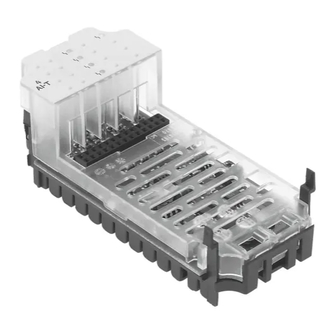
Festo CPX-AB Series Manual (346 pages)
Terminal, Analogue I/O modules, Sub-bases
Brand:
Festo
| Category:
I/O Systems
| Size: 3 MB
Table of Contents
Table of Contents
5
Intended Use
11
Areas of Application and Certification
12
Service
12
Target Group
12
Important User Instructions
13
CPX Analogue I/O Modules
15
Notes on the Use of this Manual
15
Diagnosis Via the Field Bus or a Network
18
1 Overview and Connection Technology I/O Modules
21
Overview and Connection Technology I\/O Modules
22
Components of an I/O Module
23
Overview and Connection Technology I/O Modules
23
Connection Technology
24
Combinations of Analogue I/O Modules and Sub-Bases
27
Connecting the Cables and Plugs to the Sub-Bases
28
Fitting
39
Fitting the Sub-Bases
40
Fitting the Screening/Shield Plates
43
2 Analogue Input Module CPX-2AE-U-I
45
Analogue Input Module Cpx-2Ae-U-I
46
Fitting
47
Function of the Analogue Input Modules
47
Installation
48
Analogue Input Module CPX-2AE-U-I
48
Pin Allocation
51
Connecting the Analogue Intputs
54
Instructions on Commissioning
55
Processing Analogue Input Signals
55
General Information on Parameterisation
59
Parameters of the Analogue Input Module Type CPX-2AE-U-I
61
Module Parameter "Input Analogue-Value Data Format
69
Channel-Specific Module Parameters - Limits
71
Channel-Specific Module Parameters - Measured Value Smoothing
75
Channel-Specific Module Parameters - Monitoring Wire Break
75
Diagnosis
76
Error Messages of the Analogue Input Modules
77
LED Display
79
Analogue Input Module Cpx-4Ae-U-I
84
Analogue Input Module CPX-4AE-U-I
85
Fitting
85
Function of the Analogue Input Modules
85
Installation
86
Pin Allocation
87
Connecting the Analogue Inputs
90
Instructions on Commissioning
91
Processing Analogue Input Signals
91
Procedure for Commissioning
91
General Information on Parameterisation
92
Parameters of Analogue Input Module Type CPX-4AE-U-I
93
Representation and Value Ranges of the Analogue Values
105
Scaling of the Value Range with Limit Values
110
Examples for Scaling of the Value Range
110
Diagnosis
113
Error Messages of the Analogue Input Modules
114
LED Display
116
Analogue Input Module Cpx-4Ae-I
122
Analogue Input Module CPX-4AE-I
123
Fitting
123
Function of the Analogue Input Modules
123
Installation
124
Connecting the Analogue Intputs
130
Instructions on Commissioning
131
Processing Analogue Input Signals
131
General Information on Parameterisation
135
Parameters of the Analogue Input Module Type CPX-4AE-I
137
Module Parameter "Input Analogue-Value Data Format
146
Channel-Specific Module Parameters - Limits
148
Channel-Specific Module Parameters - Measured Value Smoothing
152
Channel-Specific Module Parameters - Monitoring Wire Break
152
Diagnosis
153
Error Messages of the Analogue Input Modules
154
LED Display
156
Analogue Input Module Cpx-4Ae-T
162
Analogue Input Module CPX-4AE-T
163
Fitting
163
Function of Analogue Input Module CPX-4AE-T
163
Installation
164
Connecting Temperature Sensors to the Analogue Inputs
170
Instructions on Commissioning
173
Processing the Input Signals of Temperature Sensors
173
General Information on Parameterisation
176
Parameters of the Analogue Input Module Type CPX-4AE-T
177
Measured Value Smoothing by Parameterisation
186
Diagnosis
187
Error Messages of the Analogue Input Modules
188
LED Display
190
Analogue Input Module Cpx-4Ae-Tc
196
Analogue Input Module CPX-4AE-TC
197
Fitting
197
Function of the Analogue Input Module CPX-4AE-TC
197
Installation
198
Introduction to Temperature Measurement by Means of Thermocouples
201
Connecting Temperature Sensors to the Analogue Inputs
207
Instructions on Commissioning
207
Processing the Input Signals of Temperature Sensors
208
General Information on Parameterisation
212
Parameters of Analogue Input Module Type CPX-4AE-TC
213
Diagnosis
225
Error Messages of the Analogue Input Modules
226
LED Displays
228
Pressure Sensor Module Cpx-4Ae-P
234
Function of the Pressure Sensor Module CPX-4AE-P
235
Fitting
236
Installation
237
Installing the Pneumatic Tubing
237
Commissioning
239
Processing the Input Signals of Pressure Sensors
239
Procedure for Commissioning
239
Analogue Output Module Cpx-2Aa-U-I
262
Analogue Output Module CPX-2AA-U-I
263
Fitting
263
Function of the Analogue Output Modules
263
Installation
264
Pin Allocation X1, X2
267
Connecting the Analogue Outputs
270
Instructions on Commissioning
271
Processing Analogue Output Signals
271
General Information on Parameterisation
274
Parameter with Analogue Output Module Type CPX-2AA-U-I
276
Module Parameter "Output Analogue-Value Data Format
279
Channel-Specific Module Parameters - Limits
289
Channel-Specific Module Parameters - Monitoring Wire Break
291
Diagnosis
292
Error Messages of the Anaolgue Output Modules
293
LED Display
297
Error Treatment and Parameterisation
299
Technical Appendix
304
Technical Appendix
305
Technical Data of Analogue Input Module CPX-2AE-U-I
305
Technical Data of Analogue Input Module CPX-4AE-U-I
307
Technical Data of Analogue Input Module CPX-4AE-I
309
Technical Data of Analogue Input Module CPX-4AE-T (Temperature Module
311
Technical Data of Analogue Input Module CPX-4AE-TC (Temperature Module
313
Technical Data of Analogue Input Module CPX-4AE-P (Pressure Input Module
315
Technical Data of Analogue Output Module CPX-2AA-U-I
317
Technical Data of the Connection Blocks
319
Internal Structure of the CPX Modules
320
Connection Examples
324
Analogue Input and Output Modules
324
Connecting Temperature Sensors to the Module CPX-4AE-T
328
Connecting Temperature Sensors to the Module CPX-4AE-TC
330
Accessories (CPX Terminal
333
Advertisement
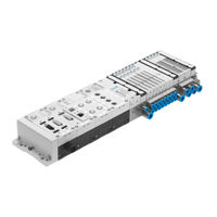
Festo CPX-AB Series Manual (308 pages)
Manual Electronics, Analogue I/O modules, Sub-bases
Brand:
Festo
| Category:
Touch terminals
| Size: 2 MB
Table of Contents
Table of Contents
5
Intended Use
11
Service
12
Target Group
12
Important User Instructions
13
CPX Analogue I/O Modules
15
Diagnosis Via the Field Bus
17
1 Overview and Connection Technology I/O Modules
21
Components of an I/O Module
24
Connection Technology
25
Display and Connecting Elements
27
Combinations of Analogue I/O Modules and Sub−Bases
28
Connecting the Cables and Plugs to the Sub−Bases
29
Assembly
40
Fitting the Sub−Bases
41
Fitting the Screening/Shield Plates
44
Analogue Input Module CPX−2AE−U−I
47
Analogue Input Module Cpx−2Ae−U−I
48
2.1 Function of the Analogue Input Modules.
48
2 Analogue Input Module CPX−2AE−U
48
Fitting
48
Installation
48
Fitting
50
Function of the Analogue Input Modules
50
Installation
51
DIL Switch Settings
52
Pin Assignment
54
Connecting the Analogue Intputs
57
Instructions on Commissioning
58
Processing Analogue Input Signals
58
General Information on Parametrizing
62
Parameters of the Analogue Input Module Type CPX−2AE−U−I
64
Module Parameter Input Analogue−Value Data Format
66
Module Parameter Input Analogue−Value Data Format"
72
Channel−Specific Module Parameters Limits
74
Channel−Specific Module Parameters Filter Measured Value
77
Channel−Specific Module Parameters Monitor of Wire Fracture
77
Diagnosis
78
Fault Messages of the Analogue Input Modules
79
LED Display
81
Fault Treatment and Parametrizing
83
Analogue Input Module Cpx−4Ae−I
86
Analogue Input Module CPX−4AE−I
87
Fitting
88
Function of the Analogue Input Modules
88
Installation
89
DIL Switch Settings
90
Pin Assignment
92
Connecting the Analogue Intputs
95
Instructions on Commissioning
96
Processing Analogue Input Signals
96
General Information on Parametrizing
100
Parameters of the Analogue Input Module Type CPX−4AE−I
102
Module Parameter Input Analogue−Value Data Format
104
Module Parameter Input Analogue−Value Data Format"
111
Channel−Specific Module Parameters Limits
113
Channel−Specific Module Parameters Filter Measured Value
116
Channel−Specific Module Parameters Monitor of Wire Fracture
116
Diagnosis
117
Fault Messages of the Analogue Input Modules
118
LED Display
120
Fault Treatment and Parametrizing
122
Analogue Input Module Cpx−4Ae−T
126
Analogue Input Module CPX−4AE−T
127
Function of Analogue Input Module CPX−4AE
128
Installation
129
DIL Switch Settings
130
Pin Assignment
132
Connecting Temperature Sensors to the Analogue Inputs
135
Instructions on Commissioning
138
Processing the Input Signals of Temperature Sensors
138
General Information on Parametrizing
141
Parameters of the Analogue Input Module Type CPX−4AE−T
142
Monitoring Wire Fracture/Short Circuit
150
Measured Value Smoothing by Parametrizing
151
Diagnosis
152
Error Messages of the Analogue Input Modules
153
LED Display
155
Error Treatment and Parametrizing
157
Analogue Input Module Cpx−4Ae−Tc
160
Analogue Input Module CPX−4AE−TC
161
Assembly
162
Function of the Analogue Input Module CPX−4AE−TC
162
Installation
163
Pin Allocation
164
Introduction to Temperature Measurement by Means of Thermocouples
166
Cold Junction Compensation
170
Connecting Temperature Sensors to the Analogue Inputs
172
Instructions on Commissioning
172
Processing the Input Signals of Temperature Sensors
173
General Information on Parametrizing
176
Parameters of Analogue Input Module Type CPX−4AE−TC
177
Diagnostics
189
Fault Messages of the Analogue Input Modules
190
LED Displays
191
Fault Treatment and Parametrizing
193
Pressure Sensor Module Cpx−4Ae−P
196
Function of the Pressure Sensor Module CPX−4AE−P
197
Assembly
198
Pressure Sensor Module CPX−4AE−P
198
Installation
199
Installing the Pneumatic Tubing
199
Commissioning
201
Processing the Input Signals of Pressure Sensors
201
Procedure for Commissioning
201
Parameters of the Pressure Sensor Module Type CPX−4AE−P
203
Parameterisation Example
214
Diagnosis
217
Error Messages of the Pressure Sensor Module CPX−4AE−P
218
LCD Display and LED Indicators
219
Error Handling and Parameterisation
221
Analogue Output Module Cpx−2Aa−U−I
224
Analogue Output Module CPX−2AA−U−I
225
Fitting
226
Function of the Analogue Output Modules
226
Installation
227
DIL Switch Settings
228
Pin Assignment
230
Connecting the Analogue Outputs
233
Instructions on Commissioning
234
Processing Analogue Output Signals
234
General Information on Parametrizing
237
Parameter with Analogue Output Module Type CPX−2AA−U−I
239
Module Parameter Output Analogue−Value Data Format
249
Channel−Specific Module Parameters Limits
251
Channel−Specific Module Parameters Monitor Wire Fracture
253
Diagnosis
254
Fault Messages of the Anaolgue Output Modules
255
LED Display
259
Fault Treatment and Parametrizing
261
Technical Appendix
266
A. Technical Appendix
266
Technical Appendix
267
Technical Specifications of Analogue Input Module CPX−2AE−U−I
267
Technical Specifications of Analogue Input Module CPX−AE−U−I
269
Technical Specifications of Analogue Input Module CPX−4AE−T (Temperature Module
271
Technical Specifications of Analogue Input Module CPX−4AE−TC (Temperature Module
273
Technical Specifications of Analogue Input Module CPX−4AE−P (Pressure Input Module
275
Technical Specifications of Analogue Output Module CPX−2AA−U−I
277
A.7 Technical Specifications of the Sub−Bases
279
Internal Structure of the CPX Modules
280
Connection Examples
284
Analogue Input and Output Modules
284
A.9 Connection Examples
284
Connecting Temperature Sensors to the Module CPX−4AE−T
288
Connecting Temperature Sensors to the Module CPX−4AE−TC
290
Accessories
293
A.10 Accessories
293
B. Index
298
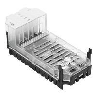
Festo CPX-AB Series Electronic Manual (228 pages)
CPX terminal/analogue I/O modules, Sub-bases type
Brand:
Festo
| Category:
Touch terminals
| Size: 1 MB
Table of Contents
Table of Contents
5
Designated Use
9
Service
10
Target Group
10
Important User Instructions
11
CPX Analogue I/O Modules
13
Diagnosis Via the Field Bus
14
Structure of a CPX Terminal
15
1 Overview and Connection Technology I/O Modules
19
Overview and Connection Technology I\/O Modules
20
Components of an I/O Module
22
Overview and Connection Technology I/O Modules
22
Connections
23
Display and Connecting Elements
25
Combinations of I/O Modules and Sub−Bases
26
Connecting the Cables and Plugs to the Sub−Bases
27
Assembly
38
Fitting the Sub−Bases
39
Fitting the Screening/Shield Plates
42
Analogue Input Module CPX−2AE−U−I
45
Analogue Input Module Cpx−2Ae−U−I
46
2 Analogue Input Module CPX−2AE−U
46
Fitting
46
Installation
46
Fitting
48
Function of the Analogue Input Modules
48
Installation
49
DIL Switch Settings
50
Pin Assignment
52
Connecting the Analogue Intputs
55
Instructions on Commissioning
56
Processing Analogue Input Signals
56
General Information on Parametrizing
60
Parameters of the Analogue Input Module Type CPX−2AE−U−I
62
Module Parameter Input Analogue−Value Data Format
70
Channel−Specific Module Parameters Limits
72
Channel−Specific Module Parameters Filter Measured Value
75
Channel−Specific Module Parameters Monitor of Wire Fracture
75
Diagnosis
76
Fault Messages of the Analogue Input Modules
77
LED Display
79
Fault Treatment and Parametrizing
81
Analogue Input Module Cpx−4Ae−I
84
Analogue Input Module CPX−4AE−I
85
Fitting
86
Function of the Analogue Input Modules
86
Installation
87
DIL Switch Settings
88
Pin Assignment
90
Connecting the Analogue Intputs
93
Instructions on Commissioning
94
Processing Analogue Input Signals
94
General Information on Parametrizing
98
Parameters of the Analogue Input Module Type CPX−4AE−I
100
Module Parameter Input Analogue−Value Data Format
102
Module Parameter Input Analogue−Value Data Format"
109
Channel−Specific Module Parameters Limits
111
Channel−Specific Module Parameters Filter Measured Value
114
Channel−Specific Module Parameters Monitor of Wire Fracture
114
Diagnosis
115
Fault Messages of the Analogue Input Modules
116
LED Display
118
Fault Treatment and Parametrizing
120
Analogue Input Module CPX−4AE−T
123
Analogue Input Module Cpx−4Ae−T
124
Analogue Input Module CPX−4AE
125
Function of Analogue Input Module CPX−4AE−T
126
Installation
127
DIL Switch Settings
128
Pin Assignment
130
Connecting Temperature Sensors to the Analogue Inputs
133
Instructions on Commissioning
136
Processing the Input Signals of Temperature Sensors
136
General Information on Parametrizing
139
Parameters of the Analogue Input Module Type CPX−4AE−T
140
Monitoring Wire Fracture/Short Circuit
148
Measured Value Smoothing by Parametrizing
149
Diagnosis
150
Error Messages of the Analogue Input Modules
151
LED Display
153
Error Treatment and Parametrizing
155
Analogue Output Module Cpx−2Aa−U−I
158
Analogue Output Module CPX−2AA−U−I
160
Function of the Analogue Output Modules
160
Installation
161
DIL Switch Settings
162
Pin Assignment
164
Connecting the Analogue Outputs
167
Instructions on Commissioning
168
Processing Analogue Output Signals
168
General Information on Parametrizing
171
Parameter with Analogue Output Module Type CPX−2AA−U−I
173
Module Parameter Output Analogue−Value Data Format
183
Channel−Specific Module Parameter Limits
185
Channel−Specific Module Parameters Monitor Wire Fracture
187
Diagnosis
188
Fault Messages of the Anaolgue Output Modules
189
LED Display
193
Fault Treatment and Parametrizing
195
Technical Appendix
200
A. Technical Appendix
200
Technical Appendix
201
Technical Specifications of Analogue Input Module CPX−2AE−U−I
201
Technical Specifications of Analogue Input Module CPX−4AE−I
203
Technical Specifications of Analogue Input Module CPX−4AE−T (Temperature Module
205
Technical Specifications of Analogue Output Module CPX−2AA−U−I
207
Technical Specifications of the Sub−Bases
209
Internal Structure of the CPX Modules
210
Connection Examples
212
Analogue Input and Output Modules
212
A.7 Connection Examples
212
Connecting Temperature Sensors to the CPX−4AE−T
215
Accessories
217
A.8 Accessories
217
B. Index
222
Advertisement
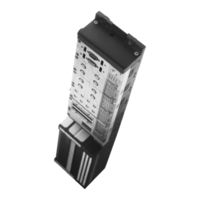
Festo CPX-AB Series Electronic Manual (232 pages)
CPX-I/O modules, sub-bases, pneumatic interfaces and MPA electronic modules
Brand:
Festo
| Category:
I/O Systems
| Size: 4 MB
Table of Contents
Table of Contents
5
Intended Use
9
Target Group
10
Service
10
Important User Instructions
11
Notes on the Use of this Manual
13
Structure of a CPX Terminal
14
CPX Pneumatic Interfaces and MPA Pneumatic Modules
15
CPX I/O Modules
15
Diagnosis Via the Field Bus
17
1 Pneumatic Interfaces
23
Fitting
30
Settings for Configuring the Pneumatics
31
Installation
36
Instructions on Commissioning
37
Diagnosis
41
Fault Messages of the Pneumatic Interfaces
42
LED Display
43
2 MPA Pneumatic Modules
47
Mpa Pneumatic Modules
48
2.5 Diagnosis
48
2.4 Instructions on Commissioning.
48
Fitting
48
Installation
48
Diagnosis
48
Composition of the LED Display on MPA1
48
Composition of the LED Display on MPA2
48
MPA Pneumatic Modules
57
Instructions on Commissioning
62
Parameters of the MPA Pneumatic Modules
62
Diagnosis
64
Composition of the LED Display on MPA1
65
Composition of the LED Display on MPA2
66
LED Messages for MPA Electronic Modules with Standard Diagnosis
68
Fault Treatment and Parametrizing
70
Input Modules
102
Function of the Input Modules
103
Input Modules
103
Mounting
104
Installation
105
Input Module CPX−4DE
106
Input Module CPX−8DE
111
Input Module CPX−8DE−D with Channel Diagnosis
116
Input Module CPX−16DE
121
Input Module CPX−16DE−D
124
Input Module CPX−8NDE
126
Instructions on Commissioning
131
Parameters of the Input Modules Type CPX−4DE, −8DE, −8DE−D, −16DE and −8NDE
131
Diagnosis
135
Fault Messages of the Input Modules
135
LED Display
137
Fault Treatment and Parametrizing
140
Output Modules
142
Function of the Output Modules
143
Mounting
143
Output Modules
143
Installation
144
Output Module CPX−4DA
145
Output Module CPX−8DA
151
High−Current Output Module CPX−8DA−H
157
Instructions on Commissioning
162
Parameters of the Output Modules Types CPX−4DA, CPX−8DA and CPX−8DA−H
162
Diagnosis
165
Error Messages of the Output Modules
166
LED Display
168
Fault Treatment and Parametrizing
170
Multi I\/O Modules
172
Multi I/O Modules
173
Fitting
174
Function of the Multi I/O Modules
174
Installation
175
Instructions on Commissioning
180
Diagnosis
186
Error Messages of the Multi I/O Modules
186
LED Display
188
Error Treatment and Parametrizing
190
Technical Appendix
192
Technical Appendix
193
Technical Specifications of the Pneumatic Interfaces
193
Technical Specifications of the MPA Electronic Modules
195
Technical Specifications of the Input Modules
197
Technical Specifications of the Output Modules
200
Technical Specifications of the Multi I/O Modules
203
Technical Specifications of the Sub−Bases in Metal Design
206
Internal Structure of the CPX Modules
207
Examples of Circuitry
212
Circuitry Examples of PNP Inputs
212
Circuitry Examples of PNP Outputs
212
Circuitry Examples of NPN Inputs
213
Circuitry Example with DUO Cable
214
Accessories
216
Festo CPX-AB Series Electronic Manual (208 pages)
Brand:
Festo
| Category:
Touch terminals
| Size: 2 MB
Table of Contents
Table of Contents
5
Designated Use
9
Target Group
10
Service
10
Important User Instructions
11
Notes on the Use of this Manual
13
CPX Pneumatic Interfaces
14
MPA Pneumatic Modules
15
CPX I/O Modules
16
Diagnosis Via the Field Bus
17
Structure of a CPX Terminal
18
Pneumatic Interfaces
23
Function of the Pneumatic Interfaces
26
Display and Connecting Elements
29
Fitting
32
Settings for Configuring the Pneumatics
33
Installation
38
Instructions on Commissioning
39
Diagnosis
43
Error Messages of the Pneumatic Interfaces
44
LED Display
45
Error Treatment and Parametrizing
47
Function of the MPA Pneumatic Modules
52
Display and Connecting Elements
54
Fitting
55
Installation
59
Instructions on Commissioning
63
Diagnosis
66
LED Display
67
Error Treatment and Parametrizing
70
Overview and Connecting Technology I/O Modules
71
Components of an I/O Module
74
Connection Technology
75
Display and Connecting Elements
78
Combinations of I/O Modules and Sub−Bases
79
Connecting the Cables and Plugs to the Sub−Bases
81
Fitting
91
Fitting the Sub−Bases
92
Fitting the Screening Plates
95
Input Modules
98
Input Modules
99
Fitting
100
Function of the Input Modules
100
Installation
101
Input Module CPX−8DE
102
Input Module CPX−8DE−D with Channel Diagnosis
107
Input Module CPX−4DE
112
Instructions on Commissioning
117
Diagnosis
121
Error Messages of the Input Modules
121
LED Display
123
Error Treatment and Parametrizing
126
Output Modules
128
Fitting
130
Function of the Output Modules
130
Output Modules
130
Installation
131
Output Module CPX−4DA
132
Output Module CPX−8DA
138
Instructions on Commissioning
144
Diagnosis
147
Error Messages of the Output Modules
148
LED Display
149
Error Treatment and Parametrizing
151
Multi I/O Modules
153
Function of the Multi I/O Modules
156
Installation
157
Multi I/O Module CPX−8DE−8DA
158
Instructions on Commissioning
162
Diagnosis
168
LED Display
170
Error Treatment and Parametrizing
172
Technical Appendix
174
A. Technical Appendix
174
Technical Appendix
175
Technical Specifications of the Pneumatic Interfaces
175
Technical Specifications of the MPA Electronic Modules
177
Technical Specifications of the Input Modules
179
Technical Specifications of the Output Modules
180
Technical Specifications of the Multi I/O Modules
182
Technical Specifications of the Sub−Bases
184
Internal Structure of the CPX Modules
185
Examples of Circuitry
189
Circuitry Examples of PNP Inputs
189
Circuitry Examples of PNP Outputs
189
A.8 Examples of Circuitry
189
Circuitry Example with DUO Cable
190
A.8.4 Circuitry Example with DNCV
191
Accessories
192
A.9 Accessories
192
B. Index
200
Festo CPX-AB Series Manual (202 pages)
Digital CPX I/O modules and Connection blocks, CPX pneumatic interfaces
Brand:
Festo
| Category:
Touch terminals
| Size: 5 MB
Table of Contents
Table of Contents
5
Intended Use
8
Areas of Application and Approval by Authorities
9
Target Group
9
Service
9
Important User Instructions
10
Notes on the Use of this Manual
12
Structure of a CPX Terminal
13
CPX I/O Modules and Connection Blocks
14
MPA Pneumatic Modules
16
CPX Pneumatic Interfaces
16
Overview and Connection Blocks for CPX I/O Modules
19
Table of Contents
20
Components of an I/O Module
21
Connection Technology
22
Overview and Connection Blocks for CPX I/O Modules
26
Display and Connecting Elements
26
Combinations of I/O Modules and Connection Blocks
28
Connecting the Cables and Plugs to the Connection Blocks
31
Assembly
41
Fitting the Connection Blocks
42
Fitting the Screening Plates
46
Digital CPX Input Modules
49
Digital Cpx Input Modules
50
Digital CPX Input Modules
51
Function of the Input Modules
51
Assembly
52
Installation
53
Input Module CPX-4DE
54
Input Module CPX-8DE
59
Input Module CPX-8DE-D with Channel Diagnosis
64
Input Module CPX-8NDE
69
Input Module CPX-16DE
74
Input Module CPX-M-16DE-D with Channel Diagnosis
77
Input Module CPX-L-16DE-16-KL-3POL
79
Instructions on Commissioning
80
Parameters of the Input Modules
80
Diagnosis
84
LED Display
86
Error Handling and Parameterisation
90
Digital CPX Output Modules
91
Digital Cpx Output Modules
92
Assembly
93
Digital CPX Output Modules
93
Function of the Output Modules
93
Installation
94
Output Module CPX-4DA
95
Output Module CPX-8DA
101
High-Current Output Module CPX-8DA-H
107
Instructions on Commissioning
112
Parameters of the Output Modules
112
Diagnosis
115
LED Display
117
Error Handling and Parameterisation
119
Digital CPX Multi I/O Modules
121
Digital Cpx Multi I\/O Modules
122
Assembly
123
Digital CPX Multi I/O Modules
123
Function of Multi I/O Modules
123
Installation
124
Multi I/O Module CPX-8DE-8DA
125
Multi I/O Module CPX-L-8DE-8DA
129
Instructions on Commissioning
130
Parameters of the Multi I/O Modules Type CPX-8DE-8DA
130
Diagnosis
136
LED Display
138
Error Handling and Parameterisation
141
CPX Pneumatic Interfaces
143
Cpx Pneumatic Interfaces
144
CPX Pneumatic Interfaces
145
Function of the CPX Pneumatic Interfaces
145
Display and Connecting Elements
147
Assembly
151
Settings for Configuring the Pneumatics
152
Installation
157
Instructions on Commissioning, Parameterisation
158
Diagnosis
162
Fault Messages of the Pneumatic Interfaces
163
LED Display
164
Error Handling and Parameterisation
166
A. Technical Appendix
167
Technical Appendix
168
Technical Appendix
169
Technical Specifications of the CPX Connection Blocks
169
Technical Specifications of the CPX Metal Connection Blocks
170
Technical Specifications of the CPX Input Modules
171
Technical Specifications of the CPX Output Modules
173
Technical Specifications of the CPX Multi I/O Modules
176
Technical Specifications of the Pneumatic Interfaces
178
B. Internal Structure and Circuitry Examples
181
Internal Structure and Circuitry Examples
183
Internal Structure of the CPX I/O Modules
183
Circuitry Examples for CPX Inputs and Outputs
188
Circuitry Example with DUO Cable
190
B.2.5 Circuitry Example with DNCV
191
Accessories (CPX Terminal
192
C. Index
194
Festo CPX-AB Series Manual (196 pages)
Digital I/O modules, sub-bases and pneumatic interfaces
Brand:
Festo
| Category:
Control Unit
| Size: 3 MB
Table of Contents
Table of Contents
5
Intended Use
9
Target Group
10
Service
10
Important User Instructions
11
Notes on the Use of this Manual
13
Structure of a CPX Terminal
14
CPX I/O Modules and Sub−Bases
15
CPX Pneumatic Interfaces
16
MPA Pneumatic Modules
16
Diagnosis Via the Field Bus or a Network
17
Overview and Sub−Bases for CPX I/O Modules
19
Components of an I/O Module
21
Connection Technology
22
Display and Connecting Elements
26
Combinations of I/O Modules and Sub−Bases
28
Connecting the Cables and Plugs to the Sub−Bases
31
Assembly
41
Fitting the Sub−Bases
42
Fitting the Screening/Shield Plates
46
Digital CPX Input Modules
49
Digital Cpx Input Modules
50
Digital CPX Input Modules
51
Function of the Input Modules
51
Assembly
52
Installation
53
Input Module CPX−4DE
54
Input Module CPX−8DE
59
Input Module CPX−8DE−D with Channel Diagnosis
64
Input Module CPX−16DE
69
Input Module CPX−M−16DE
72
Input Module CPX−8NDE
74
Instructions on Commissioning
79
Parameters of the Input Modules
79
Diagnostics
83
Fault Messages of the Input Modules
83
LED Display
85
Fault Treatment and Parameterizing
88
Digital CPX Output Modules
89
Digital Cpx Output Modules
90
Digital CPX Output Modules
91
Function of the Output Modules
91
Installation
92
Output Module CPX−4DA
93
Output Module CPX−8DA
99
High−Current Output Module CPX−8DA
105
Instructions on Commissioning
110
Parameters of the Output Modules
110
Diagnostics
113
Error Messages of the Output Modules
114
LED Display
115
Fault Treatment and Parameterizing
117
Digital CPX Multi I/O Modules
119
Digital Cpx Multi I\/O Modules
120
Assembly
121
Digital CPX Multi I/O Modules
121
Function of the Multi I/O Modules
121
Installation
122
Multi I/O Module CPX−8DE−8DA
123
Instructions on Commissioning
127
Parameters of the Multi I/O Modules Type CPX−8DE−8DA
127
Diagnostics
132
Error Messages of the Multi I/O Modules
132
LED Display
134
Fault Treatment and Parameterizing
136
Cpx Pneumatic Interfaces
138
CPX Pneumatic Interfaces
139
Function of the CPX Pneumatic Interfaces
139
Display and Connecting Elements
141
Fitting
144
Settings for Configuring the Pneumatics
145
Installation
150
Instructions on Commissioning
151
Diagnostics
155
Fault Messages of the Pneumatic Interfaces
156
LED Display
157
Fault Treatment and Parameterizing
159
Technical Appendix
162
Technical Appendix
163
Technical Specifications of the CPX Sub−Bases
163
Technical Specifications of the CPX Metal Sub−Bases
164
Technical Specifications of the CPX Input Modules
165
Technical Specifications of the CPX Output Modules
167
Technical Specifications of the CPX Multi I/O Modules
170
Technical Specifications of the Pneumatic Interfaces
172
Internal Structure and Examples of Cicuitry
176
Internal Structure of the CPX I/O Modules
177
Circuitry Examples for CPX Inputs and Outputs
182
Circuitry Examples of NPN Inputs
183
Circuitry Example with DUO Cable
184
Circuitry Example with DNCV
185
Accessories (CPX Terminal)
186
Index
188
Festo CPX-AB Series Electronic Manual (186 pages)
Brand:
Festo
| Category:
Touch terminals
| Size: 3 MB
Table of Contents
Table of Contents
5
Designated Use
9
Target Group
10
Service
10
Important User Instructions
11
Notes on the Use of this Manual
13
CPX Pneumatic Interfaces
14
MPA Pneumatic Modules
15
CPX I/O Modules
16
Diagnosis Via the Field Bus
17
Setting up a CPX Terminal
18
Pneumatic Interfaces
21
Pneumatic Interfaces
22
Pneumatic Interface
27
Fitting
28
Settings for Configuring the Pneumatics
29
Installation
34
Commissioning Instructions
35
Diagnosis
39
Fault Messages of the Pneumatic Interfaces
40
LED Display
41
Mpa Pneumatic Modules
46
MPA Pneumatic Modules
47
Function of the MPA Pneumatic Modules
48
Display and Connecting Elements
50
Fitting
51
Installation
55
Commissioning Instructions
59
Diagnosis
62
Fault Messages of the MPA Pneumatic Modules
62
Fault Treatment and Parametrizing
66
Input Modules
92
Input Modules
93
Fitting
94
Function of the Input Modules
94
Installation
95
Input Module CPX−8DE
96
Input Module CPX−4DE
101
Commissioning Instructions
106
Diagnosis
110
Fault Messages of the Input Modules
110
LED Display
111
Fault Treatment and Parametrizing
113
Output Modules
116
Fitting
118
Function of the Output Modules
118
Output Modules
118
Installation
119
Technical Appendix
154
Technical Appendix
155
Technical Specifications of the MPA Electronic Modules
156
Technical Specifications of the Input Modules
158
Technical Specifications of the Output Modules
159
Technical Specifications of the Multi I/O Modules
160
Technical Specifications of the Sub−Bases
162
Internal Structure of the CPX Modules
164
Examples of Circuitry
167
Examples of Circuitry (PNP Inputs
167
Examples of Circuitry (PNP Outputs
167
Example of Circuitry with DUO Cable
168
Accessories
170
Advertisement
Related Products
FESTO CPX-M-FB35
Festo CPX
Festo CPX-FB11
Festo CPX-FB13
Festo CPX Series
Festo CPX-...DE Series
Festo CPX-M Series
Festo CPX-GP-CPA Series
Festo CPX-CP
Festo CPX-CEC-C1
Festo Categories
Industrial Equipment
Control Unit
Controller
Touch terminals
DC Drives
More Festo Manuals
Login
Sign In
OR
Sign in with Facebook
Sign in with Google
Upload manual
Upload from disk
Upload from URL