Sign In
Upload
Manuals
Brands
Emerson Manuals
Control Systems
PACSystems RSTi-EP
Emerson PACSystems RSTi-EP Manuals
Manuals and User Guides for Emerson PACSystems RSTi-EP. We have
5
Emerson PACSystems RSTi-EP manuals available for free PDF download: User Manual, Quick Start Manual
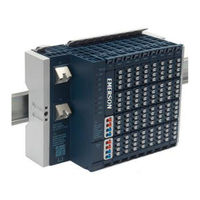
Emerson PACSystems RSTi-EP User Manual (541 pages)
Analog Input Module
Brand:
Emerson
| Category:
I/O Systems
| Size: 31 MB
Table of Contents
Table of Contents
3
Introduction
16
Revisions in this Manual
17
Pacsystems Documentation
18
Pacsystems Manuals
18
Rx3I Manuals
18
System Overview
19
Dimensions of the Rsti-EP Components
20
Double-Click Installation
20
General Description of the Fieldbus Network Adapters
21
General Technical Data for the Fieldbus Network Adapter
22
General Description of I/O Modules
23
I/O Module (Example EP-1214)
23
Color Coding
24
Standard Connector
25
Features and Specifications
25
HD Connector EP-8360
26
Cable Protection
28
General Technical Data for I/O Modules
29
Mechanical Fixing Elements
31
Type Plate
31
Markers
32
Swivel Marker
32
Safety
33
General Safety Notice
33
Electrostatic Discharge
33
Open Equipment
34
Fusing
34
Earthing (Functional Earth FE)
34
Shielding
35
Overcurrent
35
Intended Use
35
Use in a Potentially Explosive Atmosphere
35
ATEX Zone 2
36
ATEX & Iecex Marking
37
Legal Notice
37
Use of Rsti-EP Stations 2,000M above Sea Level
37
Example
37
Configuration
38
Order and Arrangement of Modules
38
Arrangement of Safe Power-Feed Modules
39
Power Supply Concept
39
Clearances
40
Calculation of Space Requirements
42
Use in a Potentially Explosive Atmosphere
42
ATEX & Iecex Marking
43
Spring-Style System Cabling
43
Current Demand and Power Supply
43
Power Supply Derating
44
Example Calculation for the Power Supply
45
Calculation of the Current Demand for the Input Current
45
Calculation of the Current Demand for the Output Current
46
Example Calculation for the Current Demand (All Current Values in Amps)
47
Calculation of Power Loss
48
Calculation of Power Loss for Use in a Potentially Explosive Atmosphere
48
Feedback Energy in DO Modules
49
Calculation of Feedback Energy
49
Parameter Overview
50
Modifiable Parameters for Network Adaptors
50
Data Width of I/O Module, Dependent on the Network Adapter Used
65
Epxpbs001
65
Epxpns001/Epxpns101
67
Epxetc001
69
Epxeip001
70
Detailed Descriptions of the Fieldbus Network Adapters
73
Profibus DP Network Adapter EPXPBS001
73
Leds
74
LED Status Indicators
74
Addressing
75
Addressing Examples
76
Connection Diagrams
77
Specifications: EPXPBS001
78
Modifiable Parameters EPXPBS001
79
Supported Modules and Power Supplies
80
PROFINET IRT/RT Network Adapter EPXPNS001/EPXPNS101
82
Leds
83
Led Indicators
84
Connection Diagrams
85
Specification: EPXPNS001/EPXPNS101
86
Modifiable Parameters: EPXPNS001/EPXPNS101
88
Network Adaptor Input Status Data
89
Hot Standby CPU Redundancy I/O Parameters (EPXPNS101)
90
Rsti-EP PROFINET Channel Diagnostic Alarm Reporting
91
Supported Modules and Power Supplies
101
Ethercat ® Network Adapter EPXETC001
102
Leds
103
Connection Diagrams
105
Specifications: EPXETC001
106
Modifiable Parameters for EPXETC001
107
Rsti-EP Status Messages
107
Module Status Messages
108
Module Diagnosis
108
Supported Modules and Power Supplies
109
Modbus ® TCP Network Adapter EPXMBE001/EPXMBE101
111
Leds
112
Connection Diagrams
113
Specifications: EPXMBE001/EPXMBE101
114
Configuration of the IP Address
115
Modifiable Parameters for EPXMBE001/EPXMBE101
115
Register Structure
116
Implemented Modbus Functions
119
Supported Modules and Power Supplies
119
Packed Process Data
121
Packed Input Process Data
121
Packed Output Process Data
121
0X1000 - 0X1006 Network Adapter Identifier
123
0X1000 - 0X1006 Network Adapter Status
123
0X1010 Process Image Length in Bits for the Output Modules
123
0X1010 Process Image Length in Bits for the Input Modules
123
0X1017 Register - Mapping Revision
123
0X1018 - 0X101B Collective Diagnostics Message for I/O Modules
124
0X101C - 0X101F Collective Process Message for I/O Modules
124
0X1028 - 0X102F Module Status
124
0X1030 MODBUS DATA EXCHANGE Watchdog, Current Time
124
0X1120 MODBUS DATA EXCHANGE Watchdog, Predefined Time
125
0X1121 MODBUS DATA EXCHANGE Watchdog Reset Register
125
0X1122 Lock Force Mode on Web Server
125
0X1031 MODBUS CONNECTION Mode Register
125
0X1131 MODBUS CONNECTION Timeout in Sec
125
0X1132 Check Reference List Prior to Data Exchange
126
0X1133 Process Alarm
126
0X1134 Diagnostic Alarm
126
0X1135 Field Bus or Reference List Error Behavior
126
0X1136 Module Removal Behavior
126
0X1137 Data Format
126
0X113C - 0X113F Save Module Parameters
127
0X27Fe Number of Entries in the Current Module List
128
0X27Ff Number of Entries in the Reference Module List
128
0X2800 - 0X287F Reference Module List
128
0X2A00 - 0X2A7F Current Module List
128
0X2B00 - 0X2B7F Module Offsets of Process Data
128
0X8000 - 0X87Ff Process Data Inputs
128
0X9000 - 0X97Ff Process Data Outputs
129
0Xa000 - 0Xa7Ff Diagnostics
129
0Xb000 - 0Xb7Ff Process Alarms
129
0Xc000 -0Xffff Parameters
129
Ethernet/Ip™ Network Adapter EPXEIP001
130
Leds
131
Connection Diagrams
133
Specifications: EPXEIP001
134
Modifiable Parameters for EPXEIP001
135
Data Types EPXEIP001
138
Process Data
140
Status Word EPXEIP001(Packed Process Data Input)
142
Object Descriptions EPXEIP001: CIP Common Classes
143
Object Descriptions EPXEIP001: Vendor Specific Classes
149
Supported Modules and Power Supplies
152
Detailed Description of I/O Modules
154
Digital Input Module EP-1214
154
LED Indicators EP-1214
155
Specifications EP-1214
156
Modifiable Parameters for EP-1214
156
Diagnostic Data EP-1214
157
Process Data Inputs EP-1214
158
Digital Input Module EP-1218
158
LED Indicators EP-1218
159
Specifications EP-1218
160
Modifiable Parameters for EP-1218
160
Diagnostic Data EP-1218
160
Process Data Inputs EP-1218
162
Digital Input Module EP-1318
162
LED Indicators EP-1318
163
Specifications EP-1318
164
Modifiable Parameters for EP-1318
164
Diagnostic Data EP-1318
165
Process Data Inputs EP-1318
166
Digital Input Module EP-1804
166
LED Indicators EP-1804
167
Specifications EP-1804
168
Diagnostic Data EP-1804
168
Process Data Inputs EP-1804
170
Digital Input Module EP-125F
170
LED Indicators EP-125F
171
Specifications EP-125F
172
Diagnostic Data EP-125F
172
Process Data Inputs EP-125F
173
Digital Input Module EP-12F4
173
LED Indicators EP-12F4
175
Specifications EP-12F4
176
Modifiable Parameters for EP-12F4
177
Diagnostic Data EP-12F4
177
Process† Data Inputs EP-12F4
178
Time Stamp Function
178
Structure of an ETS Entry
179
Digital Input Module EP-153F
182
LED Indicators EP-153F
183
Specifications EP-153F
184
Diagnostic Data EP-153F
184
Process Data Inputs EP-153F
185
Digital Output Module EP-2214
186
LED Indicators EP-2214
187
Specifications EP-2214
188
Modifiable Parameters for EP-2214
189
Diagnostic Data EP-2214
189
Process Data Outputs EP-2214
190
Digital Output Module EP-2614
190
LED Indicators EP-2614
191
Specifications EP-2614
192
Modifiable Parameters for EP-2614
193
Diagnostic Data EP-2614
193
Process Data Outputs EP-2614
194
Digital Output Module EP-2634
194
LED Indicators EP-2634
195
Specifications EP-2634
196
Modifiable Parameters for EP-2634
197
Diagnostic Data EP-2634
197
Process Data Outputs EP-2634
197
Digital Output Module EP-2218
198
LED Indicators EP-2218
198
Specifications EP-2218
200
Modifiable Parameters for EP-2218
200
Diagnostic Data EP-2218
200
Process Data Outputs EP-2218
202
Digital Output Module EP-225F
202
LED Indicators EP-225F
203
Specifications: EP-225F
204
Diagnostic Data EP-225F
205
Process† Data Outputs EP-225F
206
Digital Output Module EP-2814
207
LED Indicators EP-2814
208
Specifications EP-2814
209
Modifiable Parameters for EP-2814
209
Diagnostic Data EP-2814
209
Process Data Outputs EP-2814
210
Digital Output Module EP-2714
210
LED Indicators EP-2714
212
Specifications EP-2714
213
Modifiable Parameters for EP-2714
214
Diagnostic Data EP-2714
215
Process Data Outputs EP-2714
216
Digital Output Module EP-291F
216
LED Indicators EP-291F
217
Specifications: EP-291F
218
Diagnostic Data EP-291F
219
Data Outputs EP-291F
220
Digital Output Module EP-5111
221
LED Indicators EP-5111
222
Specifications EP-5111
223
Modifiable Parameters for EP-5111
224
Diagnostic Data EP-5111
226
Process Data† Inputs EP-5111
227
Process Data† Outputs EP-5111
227
Process Alarm Data EP-5111
229
Setting up the Counter
229
Counter Functions
230
Counting Mode
230
Counting Direction
230
Endless Counting
232
Additional Counter Features
237
Latch Function
237
Comparison Function
237
Pulse Duration
238
Digital Counter Module EP-5112
243
LED Indicators EP-5112
244
Specifications EP-5112
245
Modifiable Parameters for EP-5112
246
Diagnostic Data EP-5112
247
Process Data† Inputs EP-5112
248
Process Data† Outputs EP-5112
249
Process Alarms for EP 5112
250
Setting up the Counter
250
Counter Functions
251
Additional Counter Features
257
Digital Frequency Counter Module EP-5212
263
LED Indicators EP-5212
264
Specifications EP-5212
265
Modifiable Parameters for EP-5212
266
Diagnostic Data EP-5212
267
Process Data† Inputs EP-5212
268
Process Data† Outputs EP-5212
269
Function Frequency Counting
269
Start Measurement
269
Calculation of Results
270
Stop Measurement
270
Serial Communication Module EP-5261
272
LED Indicators EP-5261
275
Specifications EP-5261
276
Modifiable Parameters for EP-5261
277
Diagnostic Data EP-5261
277
Data Transfer
278
SSI Encoder Interface Module EP-5311
283
LED Indicators EP-5311
284
Specifications EP-5311
285
Modifiable Parameters for EP-5311
285
Diagnostic Data EP-5311
286
Process Data Inputs EP-5311
288
Digital Pulse Width Modulation Output Module EP-5422
288
LED Indicators EP-5422
289
Specifications EP-5422
290
Modifiable Parameters for EP-5422
291
Diagnostic Data EP-5422
291
Process† Data Inputs EP-5422
291
Process Data† Outputs EP-5422
292
Digital Pulse Width Modulation Output Module EP-5442
292
LED Indicators EP-5442
294
Specifications EP-5442
295
Modifiable Parameters for EP-5442
296
Diagnostic Data EP-5442
296
Process† Data Inputs EP-5442
297
Process Data† Outputs EP-5442
297
IO-Link Communication Module EP-5324
298
IO-Link Overview
299
LED Indicators EP-5324
303
Specifications EP-5324
304
Modifiable Parameters for EP-5324
304
Diagnostic Data EP-5324
308
Process Data Inputs EP-5324
310
Process Data Outputs EP-5324
311
Network Adapters-Dependent Process Data Widths
312
IO-Link Communication Module EP-5324 Event Codes
313
Analog Input Module EP-3164
314
LED Indicators EP-3164
315
Specifications EP-3164
316
Modifiable Parameters for EP-3164
317
Diagnostic Data EP-3164
317
Process Data† Inputs EP-3164
318
Measurement Range EP-3164
318
Analog Input Module EP-3264
320
LED Indicators EP-3264
321
Specifications EP-3264
322
Modifiable Parameters for EP-3164
323
Diagnostic Data EP-3264
323
Diagnostic Data EP-3264
324
Process Data† Inputs EP-3264
325
Measurement Range EP-3264
325
Analog Input Module EP-3664
327
LED Indicators EP-3664
328
Specifications: EP-3664
329
Modifiable Parameters EP-3664
330
Diagnostic Data EP-3664
330
Process Data† Inputs EP-3664
332
Measurement Range EP-3664
332
Analog Input Module EP-3124
334
LED Indicators EP-3124
335
Specifications EP-3124
336
Modifiable Parameters for EP-3124
337
Diagnostic Data EP-3124
337
Advertisement
Emerson PACSystems RSTi-EP User Manual (539 pages)
Brand:
Emerson
| Category:
Controller
| Size: 20 MB
Table of Contents
Table of Contents
2
Introduction
15
Revisions in this Manual
16
Pacsystems Documentation
17
Pacsystems Manuals
17
Rx3I Manuals
17
System Overview
18
Dimensions of the Rsti-EP Components
19
Double-Click Installation
19
General Description of the Fieldbus Network Adapters
20
General Technical Data for the Fieldbus Network Adapter
21
General Description of I/O Modules
22
I/O Module (Example EP-1214)
22
Standard Connector
24
HD Connector EP-8360
25
Cable Protection
27
General Technical Data for I/O Modules
28
Mechanical Fixing Elements
30
Type Plate
30
Markers
31
Swivel Marker
31
Safety
32
General Safety Notice
32
Electrostatic Discharge
32
Open Equipment
33
Fusing
33
Earthing (Functional Earth FE)
33
Shielding
34
Overcurrent
34
Intended Use
34
Use in a Potentially Explosive Atmosphere
34
ATEX Zone 2
35
ATEX & Iecex Marking
36
Legal Notice
36
Use of Rsti-EP Stations 2,000M above Sea Level
36
Example
36
Configuration
37
Order and Arrangement of Modules
37
Arrangement of Safe Power-Feed Modules
38
Power Supply Concept
38
Clearances
39
Calculation of Space Requirements
41
Use in a Potentially Explosive Atmosphere
41
ATEX & Iecex Marking
42
Spring-Style System Cabling
42
Current Demand and Power Supply
42
Power Supply Derating
43
Example Calculation for the Power Supply
44
Calculation of the Current Demand for the Input Current
44
Calculation of the Current Demand for the Output Current
45
Example Calculation for the Current Demand (All Current Values in Amps)
46
Calculation of Power Loss
47
Calculation of Power Loss for Use in a Potentially Explosive Atmosphere
47
Feedback Energy in DO Modules
48
Calculation of Feedback Energy
48
Parameter Overview
49
Modifiable Parameters for Network Adaptors
49
Data Width of I/O Module, Dependent on the Network Adapter Used
64
Epxpbs001
64
Epxpns001/Epxpns101
66
Epxetc001
68
Epxeip001
69
Detailed Descriptions of the Fieldbus Network Adapters
72
Profibus DP Network Adapter EPXPBS001
72
Leds
73
Addressing
74
Connection Diagrams
76
Specifications: EPXPBS001
77
Modifiable Parameters EPXPBS001
78
Supported Modules and Power Supplies
79
PROFINET IRT/RT Network Adapter EPXPNS001/EPXPNS101
81
Leds
82
Connection Diagrams
84
Specification: EPXPNS001/EPXPNS101
85
Modifiable Parameters: EPXPNS001/EPXPNS101
87
Network Adaptor Input Status Data
88
Hot Standby CPU Redundancy I/O Parameters (EPXPNS101)
89
Rsti-EP PROFINET Channel Diagnostic Alarm Reporting
90
Supported Modules and Power Supplies
100
Ethercat ® Network Adapter EPXETC001
101
Leds
102
Connection Diagrams
104
Specifications: EPXETC001
105
Modifiable Parameters for EPXETC001
106
Rsti-EP Status Messages
106
Module Status Messages
107
Module Diagnosis
107
Supported Modules and Power Supplies
108
Modbus ® TCP Network Adapter EPXMBE001/EPXMBE101
110
Leds
111
Connection Diagrams
112
Specifications: EPXMBE001/EPXMBE101
113
Configuration of the IP Address
114
Modifiable Parameters for EPXMBE001/EPXMBE101
114
Supported Modules and Power Supplies
118
Packed Process Data
120
0X1000 - 0X1006 Network Adapter Identifier
122
0X1000 - 0X1006 Network Adapter Status
122
0X1010 Process Image Length in Bits for the Output Modules
122
0X1010 Process Image Length in Bits for the Input Modules
122
0X1017 Register - Mapping Revision
122
0X1018 - 0X101B Collective Diagnostics Message for I/O Modules
123
0X101C - 0X101F Collective Process Message for I/O Modules
123
0X1028 - 0X102F Module Status
123
0X1030 MODBUS DATA EXCHANGE Watchdog, Current Time
123
0X1120 MODBUS DATA EXCHANGE Watchdog, Predefined Time
124
0X1121 MODBUS DATA EXCHANGE Watchdog Reset Register
124
0X1122 Lock Force Mode on Web Server
124
0X1031 MODBUS CONNECTION Mode Register
124
0X1131 MODBUS CONNECTION Timeout in Sec
124
0X1132 Check Reference List Prior to Data Exchange
125
0X1133 Process Alarm
125
0X1134 Diagnostic Alarm
125
0X1135 Field Bus or Reference List Error Behavior
125
0X1136 Module Removal Behavior
125
0X1137 Data Format
125
0X113C - 0X113F Save Module Parameters
126
0X27Fe Number of Entries in the Current Module List
127
0X27Ff Number of Entries in the Reference Module List
127
0X2800 - 0X287F Reference Module List
127
0X2A00 - 0X2A7F Current Module List
127
0X2B00 - 0X2B7F Module Offsets of Process Data
127
0X8000 - 0X87Ff Process Data Inputs
127
0X9000 - 0X97Ff Process Data Outputs
128
0Xa000 - 0Xa7Ff Diagnostics
128
0Xb000 - 0Xb7Ff Process Alarms
128
0Xc000 -0Xffff Parameters
128
Ethernet/Ip™ Network Adapter EPXEIP001
129
Leds
130
Connection Diagrams
132
Specifications: EPXEIP001
133
Modifiable Parameters for EPXEIP001
134
Data Types EPXEIP001
137
Process Data
139
Status Word EPXEIP001(Packed Process Data Input)
141
Object Descriptions EPXEIP001: CIP Common Classes
142
Object Descriptions EPXEIP001: Vendor Specific Classes
148
Supported Modules and Power Supplies
151
Detailed Description of I/O Modules
153
Digital Input Module EP-1214
153
LED Indicators EP-1214
154
Specifications EP-1214
155
Modifiable Parameters for EP-1214
155
Diagnostic Data EP-1214
156
Process Data Inputs EP-1214
157
Digital Input Module EP-1218
157
LED Indicators EP-1218
158
Specifications EP-1218
159
Modifiable Parameters for EP-1218
159
Diagnostic Data EP-1218
159
Process Data Inputs EP-1218
161
Digital Input Module EP-1318
161
LED Indicators EP-1318
162
Specifications EP-1318
163
Modifiable Parameters for EP-1318
163
Diagnostic Data EP-1318
164
Process Data Inputs EP-1318
165
Digital Input Module EP-1804
165
LED Indicators EP-1804
166
Specifications EP-1804
167
Diagnostic Data EP-1804
167
Process Data Inputs EP-1804
169
Digital Input Module EP-125F
169
LED Indicators EP-125F
170
Specifications EP-125F
171
Diagnostic Data EP-125F
171
Process Data Inputs EP-125F
172
Digital Input Module EP-12F4
172
LED Indicators EP-12F4
174
Specifications EP-12F4
175
Modifiable Parameters for EP-12F4
176
Diagnostic Data EP-12F4
176
Process† Data Inputs EP-12F4
177
Time Stamp Function
177
Structure of an ETS Entry
178
Digital Input Module EP-153F
181
LED Indicators EP-153F
182
Specifications EP-153F
183
Diagnostic Data EP-153F
183
Process Data Inputs EP-153F
184
Digital Output Module EP-2214
185
LED Indicators EP-2214
186
Specifications EP-2214
187
Modifiable Parameters for EP-2214
188
Diagnostic Data EP-2214
188
Process Data Outputs EP-2214
189
Digital Output Module EP-2614
189
LED Indicators EP-2614
190
Specifications EP-2614
191
Modifiable Parameters for EP-2614
192
Diagnostic Data EP-2614
192
Process Data Outputs EP-2614
193
Digital Output Module EP-2634
193
LED Indicators EP-2634
194
Specifications EP-2634
195
Modifiable Parameters for EP-2634
196
Diagnostic Data EP-2634
196
Process Data Outputs EP-2634
196
Digital Output Module EP-2218
197
LED Indicators EP-2218
197
Specifications EP-2218
199
Modifiable Parameters for EP-2218
199
Diagnostic Data EP-2218
199
Process Data Outputs EP-2218
201
Digital Output Module EP-225F
201
LED Indicators EP-225F
202
Specifications: EP-225F
203
Diagnostic Data EP-225F
204
Process† Data Outputs EP-225F
205
Digital Output Module EP-2814
206
LED Indicators EP-2814
207
Specifications EP-2814
208
Modifiable Parameters for EP-2814
208
Diagnostic Data EP-2814
208
Process Data Outputs EP-2814
209
Digital Output Module EP-2714
209
LED Indicators EP-2714
211
Specifications EP-2714
212
Modifiable Parameters for EP-2714
213
Diagnostic Data EP-2714
214
Process Data Outputs EP-2714
215
Digital Output Module EP-291F
215
LED Indicators EP-291F
216
Specifications: EP-291F
217
Diagnostic Data EP-291F
218
Data Outputs EP-291F
219
Digital Output Module EP-5111
220
LED Indicators EP-5111
221
Specifications EP-5111
222
Modifiable Parameters for EP-5111
223
Diagnostic Data EP-5111
225
Process Data† Inputs EP-5111
226
Process Data† Outputs EP-5111
226
Process Alarm Data EP-5111
228
Setting up the Counter
228
Counter Functions
229
Additional Counter Features
236
Digital Counter Module EP-5112
242
LED Indicators EP-5112
243
Specifications EP-5112
244
Modifiable Parameters for EP-5112
245
Diagnostic Data EP-5112
246
Process Data† Inputs EP-5112
247
Process Data† Outputs EP-5112
248
Process Alarms for EP 5112
249
Setting up the Counter
249
Counter Functions
250
Additional Counter Features
256
Digital Frequency Counter Module EP-5212
262
LED Indicators EP-5212
263
Specifications EP-5212
264
Modifiable Parameters for EP-5212
265
Diagnostic Data EP-5212
266
Process Data† Inputs EP-5212
267
Process Data† Outputs EP-5212
268
Function Frequency Counting
268
Serial Communication Module EP-5261
271
LED Indicators EP-5261
274
Specifications EP-5261
275
Modifiable Parameters for EP-5261
276
Diagnostic Data EP-5261
276
Data Transfer
277
SSI Encoder Interface Module EP-5311
282
LED Indicators EP-5311
283
Specifications EP-5311
284
Modifiable Parameters for EP-5311
284
Diagnostic Data EP-5311
285
Process Data Inputs EP-5311
287
Digital Pulse Width Modulation Output Module EP-5422
287
LED Indicators EP-5422
288
Specifications EP-5422
289
Modifiable Parameters for EP-5422
290
Diagnostic Data EP-5422
290
Process† Data Inputs EP-5422
290
Process Data† Outputs EP-5422
291
Digital Pulse Width Modulation Output Module EP-5442
291
LED Indicators EP-5442
293
Specifications EP-5442
294
Modifiable Parameters for EP-5442
295
Diagnostic Data EP-5442
295
Process† Data Inputs EP-5442
296
Process Data† Outputs EP-5442
296
IO-Link Communication Module EP-5324
297
IO-Link Overview
298
LED Indicators EP-5324
302
Specifications EP-5324
303
Modifiable Parameters for EP-5324
303
Diagnostic Data EP-5324
307
Process Data Inputs EP-5324
309
Process Data Outputs EP-5324
310
Network Adapters-Dependent Process Data Widths
311
IO-Link Communication Module EP-5324 Event Codes
312
Analog Input Module EP-3164
313
LED Indicators EP-3164
314
Specifications EP-3164
315
Modifiable Parameters for EP-3164
316
Diagnostic Data EP-3164
316
Process Data† Inputs EP-3164
317
Measurement Range EP-3164
317
Analog Input Module EP-3264
319
LED Indicators EP-3264
320
Specifications EP-3264
321
Modifiable Parameters for EP-3164
322
Diagnostic Data EP-3264
322
Diagnostic Data EP-3264
323
Process Data† Inputs EP-3264
324
Measurement Range EP-3264
324
Analog Input Module EP-3664
326
LED Indicators EP-3664
327
Specifications: EP-3664
328
Modifiable Parameters EP-3664
329
Diagnostic Data EP-3664
329
Process Data† Inputs EP-3664
331
Measurement Range EP-3664
331
Analog Input Module EP-3124
333
LED Indicators EP-3124
334
Specifications EP-3124
335
Modifiable Parameters for EP-3124
336
Diagnostic Data EP-3124
336
Process Data† Inputs EP-3124
337
Measurement Range EP-3124
337
Measurement Range EP-3124
338
Analog Input Module EP-3368
339
LED Indicators EP-3368
340
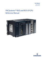
Emerson PACSystems RSTi-EP User Manual (232 pages)
Brand:
Emerson
| Category:
Computer Hardware
| Size: 2 MB
Table of Contents
Table of Contents
3
Table of Figures
8
Introduction
9
Revisions in this Manual
10
Pacsystems Control System Overview
13
Programming and Configuration
13
Process Systems
13
Pacsystems CPU Models
14
Rx3I Overview
15
Rsti-EP Overview
18
Migrating Series 90 Applications to Pacsystems
19
Documentation
20
Pacsystems Manuals
20
Rx3I Manuals
20
Field Agent Manuals
21
Rsti-EP Manuals
21
Series 90 Manuals
21
Distributed I/O Systems Manuals
21
CPU Features & Specifications
23
Common CPU Features
23
Features Shared by Certain Pacsystems CPU Models
24
Firmware Storage in Flash Memory
24
Operation, Protection, and Module Status
25
Ethernet Global Data
25
Embedded PROFINET Controller
25
Figure 1: Configuring an Embedded PROFINET Controller
26
Opc Ua
27
Removable Data Storage Devices (Rdsds)
28
Uploading a Project from the CPU to the RDSD
29
Downloading a Project from the RDSD to the CPU
30
CPU Over-Temperature Monitoring and Behavior
32
Rx3I CPU Features and Specifications
34
Rsti-EP CPU Features and Specifications
41
Cpe100/Cpe115
44
Figure 2: CPE100, Front, Top, and Bottom Views and Features
44
Figure 3: CPE100/CPE115 Membrane Pushbutton and Module Status Leds
46
Figure 4: State Diagram for CPE100/CPE115 Run/Stop Operation
47
Figure 5: Typical Multi-Tier LAN Application (Star/Bus Topology)
50
Figure 6: Typical Multi-Tier LAN Application (Ring Topology)
50
CPU Configuration
53
Configuring the CPU
53
Configuration Parameters
54
Settings Parameters
54
Modbus TCP Address Map
58
Sntp
59
Time
60
Scan Parameters
62
Memory Parameters
65
Fault Parameters
68
Redundancy Parameters (Redundancy Cpus Only)
70
Transfer List
70
COM1 and COM2 Parameters
70
Scan Sets Parameters
75
Power Consumption Parameters
76
Access Control
76
OPC UA Parameters
78
Storing (Downloading) Hardware Configuration
78
Figure 7: Downloading Hardware Config to CPU
78
Configuring the Embedded Ethernet Interface
79
Figure 8: Embedded Ethernet Interface Configuration
79
Establishing Initial Ethernet Communications
80
Setting a Temporary IP Address
81
Figure 9: Set Temporary IP Address
82
CPU Operation
85
CPU Sweep
86
Parts of the CPU Sweep
87
Figure 10: Major Phases of a Typical CPU Sweep
87
CPU Sweep Modes
91
Figure 11: Typical Sweeps in Normal Sweep Mode
91
Figure 12: Typical Sweeps in Constant Sweep Mode
93
Program Scheduling Modes
94
Window Modes
94
Figure 13: Typical Sweeps in Constant Window Mode
94
Data Coherency in Communications Windows
95
Run/Stop Operations
96
CPU STOP Modes
96
Figure 14: CPU Sweep in Stop-I/O Disabled and Stop-I/O Enabled Modes
97
STOP-To-RUN Mode Transition
99
Flash Memory Operation
100
RUN/STOP Switch Operation
101
Logic/Configuration Source and CPU Operating Mode at Power-Up
101
CPU Mode When Memory Not Preserved/Power-Up Source Is Flash
103
CPU Mode When Memory Preserved
104
Clocks and Timers
105
Elapsed Time Clock
105
Time-Of-Day Clock
105
Watchdog Timer
106
System Security
108
Passwords and Privilege Levels - Legacy Mode
108
OEM Protection - Legacy Mode
112
Enhanced Security for Passwords and OEM Protection
113
Legacy/Enhanced Security Comparison
115
Pacsystems I/O System
116
I/O Configuration
117
I/O System Diagnostic Data Collection
119
Power-Up and Power-Down Sequences
120
Communications
127
Ethernet Communications
127
Embedded Ethernet Interfaces
127
Figure 15: CPE330 Overlapping Local IP Subnet Example
128
Figure 16: Expected Response Path
130
Figure 17: Actual Response Path
130
Ethernet Interface Modules
132
Serial Communications
132
Serial Port Communications Capabilities
133
Configurable STOP Mode Protocols
134
Serial Port Pin Assignments
134
Figure 18: COM1 Port CPE400/CPL410
136
Serial Port Electrical Isolation
138
Serial Cable Lengths and Shielding
139
Serial Port Baud Rates
139
Communications Coprocessor Module (CMM)
140
Programmable Coprocessor Module (PCM)
140
Serial I/O, SNP & RTU Protocols
143
Configuring Serial Ports Using COMMREQ Function 65520
143
COMMREQ Function Example
143
Timing
144
Sending Another COMMREQ to the same Port
144
Invalid Port Configuration Combinations
144
Advertisement
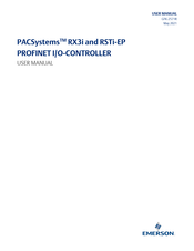
Emerson PACSystems RSTi-EP User Manual (164 pages)
PROFINET I/O-CONTROLLER
Brand:
Emerson
| Category:
I/O Systems
| Size: 8 MB
Table of Contents
Table of Contents
2
Introduction
8
Revisions in this Manual
9
PROFINET Controller Description
10
PNC001 Description
10
Embedded PROFINET Controller
12
PNC001 Module Specifications
12
Operating Range for Surrounding Air Temperature
15
Operating Temperature De-Rating
15
PNC001 Module Controls and Indicators
16
PNC001 Hardware Implementations (-Ax & -Bxxx)
17
Ethernet Network Ports
18
USB Port(S)
20
Reset Pushbutton
20
Leds on the Cpus with Embedded PROFINET
20
Leds on the PNC001 Module
20
PROFINET Networks for Pacsystems
21
Compression
22
Basic System: One Rx3I CPU and One PROFINET Controller Using a Single Port
22
Basic System: One Rx3I CPU and One PROFINET Controller Using Multiple Ports
23
Basic System: Third-Party Devices and PAC Machine Edition Programmer
23
Systems with One Rx3I CPU and Two PROFINET Controllers
24
One Rx3I CPU with Four Controllers on Separate Networks
26
Two Rx3I Cpus with Two PROFINET Networks and One Ethernet Network20
27
Systems that Use PROFINET System Redundancy (PNSR)
28
Systems that Use Hot Standby CPU Redundancy
28
Rsti-EP Standalone CPU with Embedded PROFINET Controller Using a Single Port
29
Rsti-EP Standalone CPU with Embedded PROFINET Controller Using Multiple Ports
30
Rsti-EP Standalone CPU with Embedded PROFINET Controller Using MRP
31
Glossary
32
Documentation
35
Installation
36
Pre-Installation Check
36
Installation in Hazardous Areas
37
ATEX Marking
37
Removing the Backplane Knockout
37
Module Installation
38
Module Removal
39
Hot Insertion and Removal
39
Ethernet Port Connections
41
PROFINET Network Connections
41
RJ45 Port Connections
42
Installing SFP Devices
44
Removing SFP Devices
47
PNC001 LED Behavior
48
Power-Up LED Patterns
48
Detailed LED Descriptions
49
Installing the USB Port Driver
53
Firmware Updates
53
PNC001 Firmware Updates
53
Firmware Updates for Embedded PROFINET
54
Configuration
55
Configuration Overview
55
System Planning
56
Basic Configuration Steps
57
Configuration Tools
58
Non-Volatile Configuration Parameters
58
Configuring an Rx3I PROFINET Controller
58
Configuring a Rack-Mounted Rx3I PROFINET Controller (PNC001)
58
Configuring an Embedded Rx3I PROFINET Controller
60
Configuring an Embedded Rsti-EP PROFINET Controller
61
Configuring PROFINET System Redundancy
61
Exploring PROFINET Networks
62
Configuring a PROFINET Controller on a LAN
63
Configuring PROFINET Controller Parameters
64
Configuring PROFINET Lans
67
Configuring the LAN Properties
68
Adding a Versamax PROFINET Scanner to a LAN
70
Configuring Versamax PROFINET Scanner Parameters
71
Adding Versamax PROFINET Scanner Power Supplies
76
Adding Versamax Modules to a Remote Node
77
Installing Power Supplies between Modules
78
Configuring Versamax Module Parameters
79
Adding a Third-Party IO-Device to a LAN
83
Editing Third-Party IO-Device Parameters
84
Configuring Sub-Modules of a Third-Party IO-Device
86
Viewing / Editing IO-Device Properties
87
Assigning IO-Device Names
88
After the Configuration Is Stored to the Rx3I CPU
90
PROFINET System Operation
92
PROFINET Operation Overview
92
PROFINET Communications
93
Operations of the PROFINET Controller in the Pacsystems System
95
Duplicate PROFINET IO-Device IP Address
96
Duplicate PROFINET IO-Controller IP Address
96
Resolving Duplicate IP Addresses
97
I/O Scanning
97
Data Coherency
98
Performance Factors
98
PROFINET IO Update Rate Configuration
99
Pacsystems CPU Operations for PROFINET
99
Reference ID Variables for the Pacsystems Application
99
PNIO_DEV_COMM Function Block
101
Reset Smart Module for the PROFINET Controller
102
DO I/O for Remote IO Modules
102
Scan Set I/O for Remote I/O Modules
103
Pacsystems CPU Defaults - Inputs
103
Pacsystems CPU Defaults - Outputs
104
Emerson PACSystems RSTi-EP Quick Start Manual (33 pages)
STANDALONE 1GHz PROGRAMMABLE CONTROLLER
Brand:
Emerson
| Category:
Controller
| Size: 0 MB
Table of Contents
Table of Contents
2
User Features
4
Membrane Run/Stop Pushbutton
6
LED Indicators (Leds)
6
Ethernet Ports
8
USB Port
12
Serial Ports
12
Hardware Installation
13
Initial Checks
13
Installation & Mounting
14
Grounding
17
Module Start-Up
18
Power-Up Time
18
Programming the CPE115
20
Backwards Compatibility
20
PROFINET Controller Configuration
20
OPC UA Server Configuration
21
Serial Port Configuration
21
Performance with Typical Configuration
23
Replacement of Internal Supercapacitor
25
Troubleshooting Faqs
28
Additional Information
32
Advertisement
Related Products
Emerson PACSystems
Emerson PACSystems Versamax
Emerson PaCSystems VersaMax Series
Emerson PACSystems RXi Series
Emerson PACSystems RXi
Emerson PACSystems Advanced PROFINET Scanner
Emerson PACSystems RXi Panel PC
Emerson PACSystems RXi Web panel
Emerson PACSystems RXi Industrial Monitor
Emerson PACSystems RX3i Energy Pack
Emerson Categories
Controller
Control Unit
Transmitter
Measuring Instruments
Fan
More Emerson Manuals
Login
Sign In
OR
Sign in with Facebook
Sign in with Google
Upload manual
Upload from disk
Upload from URL