Emerson Micro Motion User Manual
Ethernet/ip module
Hide thumbs
Also See for Micro Motion:
- Configuration and use manual (212 pages) ,
- Installation manual (74 pages) ,
- Quick start manual (58 pages)
Table of Contents
Advertisement
Quick Links
Download this manual
See also:
Installation Manual
Advertisement
Table of Contents

Related Manuals for Emerson Micro Motion


Summary of Contents for Emerson Micro Motion
- Page 1 User Guide MMI-20019808, Rev AE January 2019 ® Micro Motion EtherNet/IP Module...
- Page 2 Micro Motion employees. Micro Motion will not accept your returned equipment if you fail to follow Micro Motion procedures. Return procedures and forms are available on our web support site at www.emerson.com, or by phoning the Micro Motion Customer Service department.
-
Page 3: Table Of Contents
2.2 Set up the module with MVD Direct Connect..................9 2.3 Set up the transmitter ........................10 2.4 Mount, wire, and set the network settings..................10 2.5 Micro Motion Ethernet Config Tool installation (optional).............. 13 2.6 Configure the EtherNet/IP Module....................14 Chapter 3 Basic network configuration..................15 3.1 TCP/IP settings.......................... - Page 4 Contents User Guide January 2019 MMI-20019808 B.3 I/O data............................44 B.4 Get and Set services........................56 B.5 Data types............................57 B.6 Codes and integer values........................58 B.7 Status words...........................66 Appendix C Specifications.......................73 Micro Motion EtherNet/IP Module...
-
Page 5: Before You Begin
• The transmitter configuration and use manual Functional overview The EtherNet/IP Module acts as a gateway between the serial output of a Micro Motion device and an EtherNet/IP network. Using a web browser, the module supports: • Process monitoring and control •... - Page 6 C. EtherNet/IP Module D. Modbus/RS-485 E. Transmitter (see Product Data Sheet for compatible transmitters) F. To sensor G. PC with Micro Motion Ethernet Config Tool H. Configuration loop (with configuration cable) I. Other devices (SCADA, PC, Inverter) J. Web browser Figure 1-2: EtherNet/IP Module in an MVD Direct Connect installation A.
-
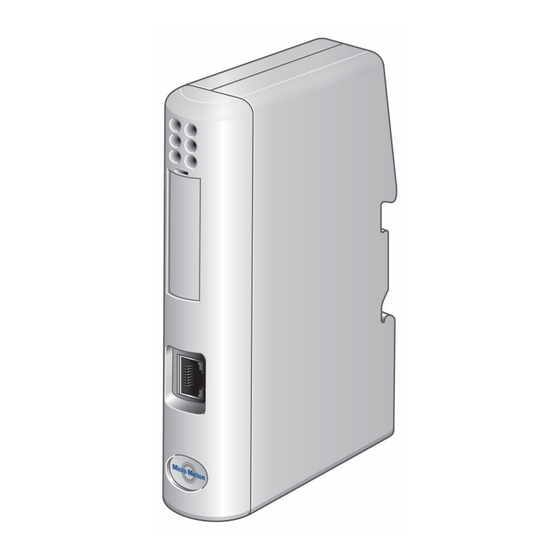
Page 7: External View Of Device
Alternative web pages To support the petroleum measurement or concentration measurement application, Micro Motion supplies alternate sets of web pages and configuration files. These are available for download from the Emerson web site. User Guide... - Page 8 Before you begin User Guide January 2019 MMI-20019808 Micro Motion EtherNet/IP Module...
-
Page 9: Chapter 2 Installation
Ensure that you have all required components: • Micro Motion EtherNet/IP Module • Power connector • Micro Motion EtherNet/IP Resource CD — Micro Motion EtherNet/IP Module User Manual — EDS file — MicroMotion Ethernet Config Tool • Configuration cable •... -
Page 10: Set Up The Transmitter
1. Ensure that the following slot registers are available for use by the EtherNet/IP Module: • 655–750 • 751–846 If these slot registers are currently in use, you must reprogram your Modbus interface. 2. Mount the EtherNet/IP Module on the DIN rail. Figure 2-2: Snap on Micro Motion EtherNet/IP Module... - Page 11 User Guide Installation MMI-20019808 January 2019 Figure 2-3: Snap off 3. Wire the EtherNet/IP Module to power (24 VDC). Figure 2-4: Power connections on the EtherNet/IP module A. 24 VDC B. Ground 4. Install the Modbus serial cable between the EtherNet/IP Module and the RS-485 terminals on the transmitter (or the I.S.
- Page 12 13. Add the EtherNet/IP Module to the Ethernet network control system. The EDS file is available on the Resource CD, the EtherNet/IP Module (download from Administration page), and the Emerson web site. Micro Motion EtherNet/IP Module...
-
Page 13: Micro Motion Ethernet Config Tool Installation (Optional)
Model 2500 Model 2700 with analog outputs Model 3500 with screw-type or solder-tail terminals Model 3500 with I/O cables Model 3700 Micro Motion Ethernet Config Tool installation (optional) Related tasks Install the Ethernet Config Tool 2.5.1 Ethernet Config Tool system requirements •... -
Page 14: Configure The Ethernet/Ip Module
Installation User Guide January 2019 MMI-20019808 Note For information on the Micro Motion Ethernet Config Tool user interface, see the Anybus Communicator manual. Related concepts Micro Motion Ethernet Config Tool installation (optional) Configure the EtherNet/IP Module Procedure 1. From your browser, login to the EtherNet/IP Module as user admin. -
Page 15: Basic Network Configuration
3.1.1 Micro Motion web page for network configuration The Network Configuration page, in the Micro Motion web pages, allows you to set the IP address, gateway address, and subnet address. If you connect to the EtherNet/IP Module using a crossover cable and the default IP address, you can set all three parameters. The changes will take effect at the next connection. - Page 16 If you change the network settings using the Ethernet Config Tool, you will not be able to use the Micro Motion web pages to change network settings in the future. All future changes to network settings must be performed using the Ethernet Config Tool.
-
Page 17: Modbus Serial Network Settings
User Guide Basic network configuration MMI-20019808 January 2019 [FTP] xxx.xxx.xxx.xxx (All nodes listed can access the EtherNet/IP Module FTP server) [EtherNet/IP] xxx.xxx.xxx.xxx (All nodes listed can access the EtherNet/IP Module via EtherNet/IP) [All] xxx.xxx.xxx.xxx (Fallback setting; used when one or more of the above keys is omitted) Modbus serial network settings... - Page 18 Basic network configuration User Guide January 2019 MMI-20019808 Micro Motion EtherNet/IP Module...
-
Page 19: Emerson Web Server
Your browser will automatically directed to the Emerson web pages. Web server access information Ports The web server communicates through port 80. Users Two users are predefined for the Emerson web pages. You can change the passwords, but you cannot add or delete users. Username Default password Description... - Page 20 Emerson web server User Guide January 2019 MMI-20019808 Micro Motion EtherNet/IP Module...
-
Page 21: Integrate With Rockwell Programming Software
Select OK. i) On the Select Module Type window, select Close. 4. To add the Micro Motion EtherNet/IP module to the RSLogix 5000 Ethernet network, right-click the Ethernet network and select New Module. a) From the Select Module Type window, select the following options and... -
Page 22: Integrate With Rockwell Versions 19 Or Earlier
Integrate with Rockwell versions 19 or earlier Use this section if you have Rockwell RSLogix 5000 version 19 or earlier firmware and programming software. These early versions do not support Micro Motion Ethernet/IP module Electronic Data Sheet (EDS)-generated Add On Profile (AOP). Instead, you must use the generic module hardware tree. - Page 23 7. Select the Slot where your Ethernet card is located. 8. Press OK. 9. To add the Micro Motion EtherNet/IP module to the RSLogix 5000 Ethernet network, right-click the Ethernet network and select New Module. a) Select the ETHERNET-MODULE Generic Ethernet Module and press OK.
- Page 24 Entry Configuration Assembly Instance: 3 Size: 0 Table 5-2: Concentration measurement Parameter Entry Name MicroMotion_EIP Description Micro Motion EtherNet/IP Module CM Comm Format Data-INT IP Address Your IP address Input Assembly Instance: 100 Size: 42 Output Assembly Instance: 150 Size: 7...
- Page 25 User Guide Integrate with Rockwell programming software MMI-20019808 January 2019 If you are not using RSLogix or Studio 5000 Logix designer, use your standard method. For information on I/O assemblies, see data. User Guide...
- Page 26 Integrate with Rockwell programming software User Guide January 2019 MMI-20019808 Micro Motion EtherNet/IP Module...
-
Page 27: Chapter 6 Troubleshooting
Minor fault. The module may or may not be able to recover. Solid red Major fault. No recovery is possible. The module must be retuned to Micro Motion for repair. See the manual for the return policy. Flashing green/red Self-test. -
Page 28: Common Problems
Configuration upload or download problem Cause The serial communication failed. Recommended actions Try again. 6.2.2 Red Config Line LED The Config Line LED turns red in the Ethernet Config Tool. Cause The serial communication failed. Recommended actions Try again. Micro Motion EtherNet/IP Module... - Page 29 User Guide Troubleshooting MMI-20019808 January 2019 6.2.3 Cannot connect to the EtherNet/IP Module The serial port seems to be available, but it is not possible to connect to the EtherNet/ IPModule. Cause The serial port may be in use by another application. Recommended actions 1.
- Page 30 4. If no data is being received, check the cables and connections. Also verify that the transmitted data is correct. 6.2.6 Process variables display or report 0 Recommended actions Verify the Modbus connection between the EtherNet/IP Module and the device. Micro Motion EtherNet/IP Module...
-
Page 31: Appendix A Connector Pin Assignments
Use 60/75 or 75 x C copper (CU) wire only. • The terminal tightening torque must be between 5 and 7 lbs-in (0.5 to 0.8 Nm). Micro Motion Ethernet Config Tool installation (optional) Related tasks Install the Ethernet Config Tool... -
Page 32: Modbus Serial Network Interface
EtherNet/IP Module Resource CD and follow the on-screen instructions. 2. Connect the configuration cable from your PC to the EtherNet/IP Module. Note For information on the Micro Motion Ethernet Config Tool user interface, see the Anybus Communicator manual. Related concepts Micro Motion Ethernet Config Tool installation (optional) Modbus serial network interface The Modbus serial network is based on an RS-485 physical layer. - Page 33 Additionally, if the distance from the EtherNet/IP Module to the transmitter is greater than 100 feet, Micro Motion recommends adding the termination resistors. The resistor value should ideally match the characteristic impedance of the cable, typically 100 to 120 Ω.
-
Page 34: Typical Connection
Connector pin assignments User Guide January 2019 MMI-20019808 Typical connection A. Signal ground B. Cable shield C. Node D. Signal ground Micro Motion EtherNet/IP Module... -
Page 35: Appendix B Device Profile
User Guide Device profile MMI-20019808 January 2019 Device profile Object classes Table B-1 lists and describes all object classes supported by the EtherNet/IP Module. Table B-1: Object classes and descriptions Object Class ID Optional/ Description required Identity 0x01 Required Contains information that uniquely describes the device Message Router... - Page 36 UINT Default: 0392h Micro Motion Inc Device Type UINT Default: 000Ch Communication Adapter Product Code UINT Default: 0002h 2 = Micro Motion EtherNet/IP Module Revision Struct of: USINT Major fieldbus version USINT Minor fieldbus version Status WORD Device status; see following table...
- Page 37 User Guide Device profile MMI-20019808 January 2019 Bit(s) Name 0000b Unknown 0010b Faulted I/O Connection 0011b No I/O connection established 0100b Non-volatile configuration bad 0110b Connection in Run mode 0111b Connection in Idle mode (other) (reserved) Set for minor recoverable faults Set for minor unrecoverable faults Set for major recoverable faults Set for major unrecoverable faults...
- Page 38 The highest initiated instance number Instance attributes - Instance/Connection Point 64h This instance corresponds to I/O Data (Input) in the Micro Motion EtherNet/IP Module. The EtherNet/IP Module supports two different configurations. Specific input assembly attributes depend on the configuration in use.
- Page 39 This behavior is specific to devices from Rockwell Automation and is not defined in the EtherNet/IP specification. However, since all known PLCs are implemented this way, the Micro Motion EtherNet/IP Module adopts this behavior and strips off the corresponding four bytes from the consumed data.
- Page 40 2: Configuration from DHCP Port Object Struct of: Path Size UINT 0002h 2 words Path Padded EPATH 20 F6 24 01h Path to Ethernet Class, Instance 1 Get/Set Interface Struct of: Configuration IP Address UDINT IP address Micro Motion EtherNet/IP Module...
- Page 41 User Guide Device profile MMI-20019808 January 2019 Access Name Type Value Comments Subnet Mask UDINT Subnet mask Gateway Address UDINT Gateway Address Name Server 1 UDINT Primary DNS Name Server 2 UDINT Secondary DNS Domain Name STRING Default domain name Get/Set Host Name STRING...
- Page 42 Type Value Description Revision UINT 0001h Revision 1 Instance attributes, Instance 01h Each attribute corresponds to a block of Input Data. Access Name Type Description 01h Get Data Array of USINT Mapped block of Input Data Micro Motion EtherNet/IP Module...
- Page 43 User Guide Device profile MMI-20019808 January 2019 Access Name Type Description 02h Get Data Array of USINT Mapped block of Input Data 32h Get Data Array of USINT Mapped block of Input Data The specific parameters in the block depend on the configuration in use. Configuration Input parameters (explicit data) Basic...
-
Page 44: I/O Data
Valid only when Gas Standard Volume is enabled. rate 36–39 Gas standard volume total Float Valid only when Gas Standard Volume is enabled. B.3.2 Output assembly for standard configuration Byte Access Name Type Notes 0–3 Get/Set External Temperature Float Micro Motion EtherNet/IP Module... - Page 45 User Guide Device profile MMI-20019808 January 2019 Byte Access Name Type Notes 4–7 Get/Set External Pressure Float Get/Set Start/Stop Totals Byte 0: Stop 1: Start Get/Set Reset All Process Totals Byte 0: No action 1: Reset Get/Set Reset All Inventory Totals Byte 0: No action 1: Reset...
- Page 46 Smart Meter Verification State Table B-24 at Abort Smart Meter Verification % complete Progress Enable/Disable Gas Standard Volume Calculations Subnet communication status No trigger byte 0: Communications failure (RS-485 connection to Any other value: transmitter) Communications good Micro Motion EtherNet/IP Module...
- Page 47 User Guide Device profile MMI-20019808 January 2019 B.3.4 Output parameters (explicit data) for standard configuration Class B1h, Instance 01h Attribute Access Name Type Trigger byte Description write attribute Get/Set Standard or special mass flow Table B-7 rate unit Get/Set Density unit Table B-13 Get/Set Temperature unit...
- Page 48 48–51 Net volume total Float 52–55 Net volume inventory Float 56–59 Reference density Float 60–63 Specific gravity Float 64–67 Concentration Float 68–71 Density (fixed Baume Float units) 72–75 Volume total (liquid) Float 76–79 Drive gain Float Micro Motion EtherNet/IP Module...
- Page 49 User Guide Device profile MMI-20019808 January 2019 Byte Access Name Type Notes 80–81 Status word U16 or Word • For Model 1700 Analog, Model 2700 Analog, Model 1500 Analog, Model 2500, and all Series 3000 transmitters: SNS Status Word 1 (see Status Word •...
- Page 50 No trigger byte Smart Meter Verification: Run Count Smart Meter Verification: Table B-22 Status Smart Meter Verification Table B-21 Algorithm State Smart Meter Verification Abort Table B-23 Code Smart Meter Verification State Table B-24 at Abort Micro Motion EtherNet/IP Module...
- Page 51 User Guide Device profile MMI-20019808 January 2019 Attribute Access Name Type Trigger Byte Description WriteAttribute Smart Meter Verification % complete Progress Concentration units code Derived variable Table B-17 Active matrix Subnet communication status No trigger byte 0: Communications failure (RS-485 connection to Any other value: transmitter) Communications good...
- Page 52 Model 1500 Analog, Model 2500, and all Series 3000 transmitters: SNS Status Word 2 (see Status Word • For MVD Direct Connect and 9739 MVD transmitters: SNS Status Word 1 (see Status Word 32–35 Temperature-corrected Float density Micro Motion EtherNet/IP Module...
- Page 53 User Guide Device profile MMI-20019808 January 2019 Byte Access Name Type Notes 36–39 Float 40–43 Temperature-corrected Float volume flow 44–47 Temperature-corrected Float volume total 48–51 Temperature-corrected Float volume inventory 52–55 Average temperature- Float corrected density 56–59 Average temperature Float B.3.10 Output assembly for petroleum measurement configuration Byte...
- Page 54 No trigger byte Smart Meter Verification: Run Count Smart Meter Verification: Table B-22 Status Smart Meter Verification Table B-21 Algorithm State Smart Meter Verification Abort Table B-23 Code Smart Meter Verification State Table B-24 at Abort Micro Motion EtherNet/IP Module...
- Page 55 User Guide Device profile MMI-20019808 January 2019 Attribute Access Name Type Trigger Byte Description WriteAttribute Smart Meter Verification % complete Progress API Table Type Table B-18 Reference temperature Float Thermal expansion coefficient Float (TEC) Subnet communication status No trigger byte 0: Communications failure (RS-485 connection to Any other value:...
-
Page 56: Get And Set Services
The data type of the returned attribute B.4.2 Set Attribute Single service Table B-4: Set service arguments Parameter name Data type Required Parameter value Notes Attribute ID USINT The attribute ID of the No default attribute to be set Micro Motion EtherNet/IP Module... -
Page 57: Data Types
User Guide Device profile MMI-20019808 January 2019 Table B-4: Set service arguments (continued) Parameter name Data type Required Parameter value Notes Attribute Value The data type of The value to which the No default the attribute attribute will be set being set Table B-5: Set service response Return value... -
Page 58: Codes And Integer Values
Short tons (2000 pounds) per day Long tons (2240 pounds) per hour Long tons (2240 pounds) per day Special Table B-8: Mass totalizer and mass inventory measurement unit codes Code Description Grams Kilograms Metric tons Pounds Short tons (2000 pounds) Micro Motion EtherNet/IP Module... - Page 59 User Guide Device profile MMI-20019808 January 2019 Table B-8: Mass totalizer and mass inventory measurement unit codes (continued) Code Description Long tons (2240 pounds) Special Table B-9: Liquid volume flow measurement unit codes Code Description Cubic feet per minute U.S. gallons per minute Liters per minute Imperial gallons per minute Cubic meters per hour...
- Page 60 Code Description Normal cubic meters per hour Normal liters per hour Standard cubic feet per minute Normal liters per day Normal liters per minute Normal liters per second Standard liters per day Standard liters per hour Micro Motion EtherNet/IP Module...
- Page 61 User Guide Device profile MMI-20019808 January 2019 Table B-11: Gas standard volume flow measurement unit codes (continued) Code Description Standard liters per minute Standard liters per second Normal cubic meters per day Normal cubic meters per minute Normal cubic meters per second Standard cubic feet per day Standard cubic feet per hour Standard cubic feet per second...
- Page 62 Inches mercury @ 0 °C Feet water @ 68 °F Millimeters water @ 68 °F Millimeters mercury @ 0 °C Pounds per square inch Millibar Grams per square centimeter Kilograms per square centimeter Pascals Kilopascals Torr @ 0 °C Atmospheres Micro Motion EtherNet/IP Module...
- Page 63 User Guide Device profile MMI-20019808 January 2019 Table B-15: Pressure and differential pressure measurement unit codes (continued) Code Description Inches water @ 60 °F Megapascals Inches water @ 4 °C Millimeters water @ 4 °C Not available with the standard core processor. Table B-16: Concentration measurement unit codes Code Description...
- Page 64 Table B-19: Fixed output codes for Smart Meter Verification Value Description Last measured value Fault value Table B-20: Enable Smart Meter Verification Code Description Enable with fixed output (see Table B-19) Abort Enable with continuous measurement Micro Motion EtherNet/IP Module...
- Page 65 User Guide Device profile MMI-20019808 January 2019 Table B-21: Smart Meter Verification algorithm state Value Description Inactive Performing startup checks Cutting drive setpoint Initializing filters Setting test tones Ramping test tones Checking drive stability Setting drive voltage measurement Verifying drive voltage Resetting DAQ/MUX Setting current calibration Calibrating current amplitude...
-
Page 66: Status Words
Contact Micro Motion customer service and provide the abort code. Other General abort. Repeat the test. If the test aborts again, contact Micro Motion customer service and provide the abort code. Table B-24: Smart Meter Verification state at abort Value Description... - Page 67 User Guide Device profile MMI-20019808 January 2019 Bit number Status description Calibration Failure (Zero, Density, Temperature) Other Failure Transmitter Initializing/Warming Up (Low Power Fault) Primary Variable Out-Of-Limits Non-Primary Variable Out-Of-Limits Simulation Mode Active (A132) Undefined Watchdog Error Cold Start (HART bit) Transmitter Configuration Changed (HART bit) Fault (Failure has occurred which affects accuracy) B.7.2...
- Page 68 Line RTD Temperature Out-Of-Range (A016) Case/Meter RTD Temperature Out-Of-Range (A017) Flow Direction (0=Forward/Zero, 1=Reverse) Factory Configuration Data Is Invalid Concentration Measurement: Unable to fit curve data (A120) Last Measured Value Override Active Enhanced Density Extrapolation Alarm (A121) Micro Motion EtherNet/IP Module...
- Page 69 User Guide Device profile MMI-20019808 January 2019 Bit number Status description Cal Factors Unentered (Flocal Mandatory) (A020) 1000/2000/3000 EEPROM Checksum Error (A018) 1000/2000/3000 RAM Test Error (A019) Unrecognized/Unentered Sensor Type (K1 Mandatory) (A021) Core configuration database corrupt (A022) Core powerdown totals corrupt (A023) Core program corrupt (A024) B.7.5 Status Word 5...
- Page 70 Discrete Batch: Batch Primary Valve for 1500 and Series 3000 Only Discrete Batch: Batch Secondary Valve for 1500 and Series 3000 Only Incorrect Board Type (A30) Discrete Batch: Start Not Okay for 1500 and Series 3000 Only Micro Motion EtherNet/IP Module...
- Page 71 User Guide Device profile MMI-20019808 January 2019 Note Not all alarms are applicable to all transmitters. For more information, see the transmitter configuration manual for your transmitter. B.7.7 Status Word 7 Bit number Status description K1/FCF Combination Unrecognized Warming Up Low Power (A031) Tube Not Full (A033) Smart Meter Verification / Outputs in fault (A032)
- Page 72 Device profile User Guide January 2019 MMI-20019808 Micro Motion EtherNet/IP Module...
-
Page 73: Appendix C Specifications
User Guide Specifications MMI-20019808 January 2019 Specifications Physical specifications Physical specifications Description Housing Plastic housing with snap-on connection to DIN rail Protection class: IP20 Dimensions 4.72 in x 2.95 in x 1.06˝ LxWxH (120 mm x 75mm x 27mm) Electrical specifications Electrical specifications Description Power supply... - Page 74 Specifications User Guide January 2019 MMI-20019808 Galvanic isolation on Modbus serial interface EN 60950-1 (2001) Pollution Degree 2 Material Group IIIb 250 VRMS or 250 VDC: Working voltage 500 V: Secondary circuit transient rating Micro Motion EtherNet/IP Module...
-
Page 75: Mmi-20019808 January
User Guide MMI-20019808 January 2019 User Guide... - Page 76 © 2019 Micro Motion, Inc. All rights reserved. The Emerson logo is a trademark and service mark of Emerson Electric Co. Micro Motion, ELITE, ProLink, MVD and MVD Direct Connect marks are marks of one of the Emerson Automation Solutions family of companies. All other marks are property of their respective owners.
Need help?
Do you have a question about the Micro Motion and is the answer not in the manual?
Questions and answers