Emerson Micro Motion Installation Manual
Model d and dt sensors
Hide thumbs
Also See for Micro Motion:
- Configuration and use manual (212 pages) ,
- User manual (76 pages) ,
- Quick start manual (58 pages)

Related Manuals for Emerson Micro Motion


Summary of Contents for Emerson Micro Motion
-
Page 1: Micro Motion
Installation and Operation Manual P/N 1005172, Rev. C August 2008 ® Micro Motion Model D and DT Sensors Instruction Manual... - Page 2 ©2008, Micro Motion, Inc. All rights reserved. ELITE and ProLink are registered trademarks, and MVD and MVD Direct Connect are trademarks of Micro Motion, Inc., Boulder, Colorado. Micro Motion is a registered trade name of Micro Motion, Inc., Boulder, Colorado. The Micro Motion and Emerson logos are trademarks and service marks of Emerson Electric Co. All other trademarks...
-
Page 3: Table Of Contents
Customer Service ........® Micro Motion Model D and DT Sensors Instruction Manual... - Page 4 ........Appendix D Return Policy ..... . ® Micro Motion Model D and DT Sensors Instruction Manual...
-
Page 5: Before You Begin
4-wire remotely mounted transmitter or to a user- supplied remote host. All Model D and DT sensors may be connected to the Micro Motion transmitters listed in Table 1. The D600 sensor may be connected to the transmitters listed in Table 2. - Page 6 (1)A direct host is a user-supplied remote controller, PLC, or other device. European installations This Micro Motion product complies with all applicable European directives when properly installed in accordance with the instructions in this quick reference guide. Refer to the EC declaration of conformity for directives that apply to this product.
- Page 7 Sensor housing DS065, DS100, DH100, DS150, DH150, DS300, and DH300 sensors Flow direction Junction box arrow Process connection Purge connection (optional) Calibration tag Sensor housing Approvals Purge connection (optional) Ground screw ® Micro Motion Model D and DT Sensors Instruction Manual...
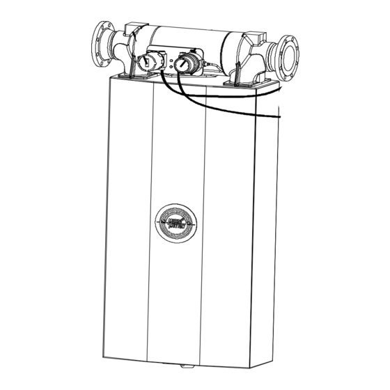
- Page 8 D600 sensor with integral booster amplifier and core processor Process connection Booster amplifier Core processor Flow direction arrow Approval tag Customer tag (if Calibration tag requested) Sensor housing Snub mount connector ® Micro Motion Model D and DT Sensors Instruction Manual...
- Page 9 Explosion-proof wiring Intrinsically safe wiring Factory-supplied wiring Process connection Approval tag Flow direction arrow Approval Calibration tag Customer tag (if requested) Core processor Sensor housing Remote booster amplifier Snub mount connector ® Micro Motion Model D and DT Sensors Instruction Manual...
-
Page 10: The Installation Process
Installing the sensor in the pipeline. See page 17. Step 4. Wiring Connecting the flowmeter cable to the sensor and transmitter. See page 19. Step 5. Startup Requirements for flowmeter startup. See page 39. ® Micro Motion Model D and DT Sensors Instruction Manual... -
Page 11: Additional Information
• Purge fittings are described in Appendix A, page 55. • Rupture disks are discussed in Appendix B, page 59. • Maintenance of labels is covered in Appendix C, page 61. • Return policy for Micro Motion equipment is described in Appendix D, page 65. ®... - Page 12 ® Micro Motion Model D and DT Sensors Instruction Manual...
-
Page 13: Step 2. Location
• The sensor must be installed in an area that is compatible with the classification specified on the sensor approvals tag. (See illustrations, pages 3-6.) Pipe run Micro Motion sensors do not require a straight run of pipe upstream or downstream. Maximum wiring distances Use these guidelines for calculating maximum wiring distances. -
Page 14: Dt Sensor Junction Box
A shutoff valve, downstream from the sensor, is required to halt flow during the zeroing procedure. For more information about zeroing, see page 39. ® Micro Motion Model D and DT Sensors Instruction Manual... -
Page 15: Hazardous Area Installations
For hazardous installations in Europe, refer to standard EN 60079-14 if national standards do not apply. If you don’t have access to the World Wide Web, you can obtain an I.S. manual by contacting the Micro Motion Customer Service Department: • In the U.S.A., phone 1-800-522-MASS (1-800-522-6277), 24 hours •... - Page 16 ® Micro Motion Model D and DT Sensors Instruction Manual...
-
Page 17: Step 3. Orientation
The sensor will function properly in any orientation if the sensor flow tubes remain filled with process fluid. Flow direction Micro Motion sensors measure accurately regardless of flow direction as long as the sensor flow tubes remain filled with process fluid. Flow direction arrow The sensor has a flow direction arrow (see illustrations, pages 3-6) to help you configure the transmitter for flow direction. - Page 18 Horizontal pipeline Vertical pipeline DH100 Self-draining DS150 DH150 DS300 DH300 Flow D600 DT65 Tubes down Tubes up Flag mount DT065 Horizontal pipeline Horizontal pipeline Vertical pipeline DT100 Self-draining DT150 Flow ® Micro Motion Model D and DT Sensors Instruction Manual...
- Page 19 Self-draining Horizontal pipeline DS150 DH150 DS300 DH300 Flow D600 DT65 Tubes up Flag mount Dry gases only DT065 Horizontal pipeline Vertical pipeline Tubes down DT100 Self-draining Horizontal pipeline DT150 Flow ® Micro Motion Model D and DT Sensors Instruction Manual...
- Page 20 Flag mount Tubes up DS100 Vertical pipeline Horizontal pipeline DH100 Self-draining DS150 DH150 DS300 DH300 Flow D600 DT65 Flag mount Tubes up DT065 Vertical pipeline Horizontal pipeline DT100 Self-draining DT150 Flow ® Micro Motion Model D and DT Sensors Instruction Manual...
-
Page 21: Step 4. Mounting
• For optional D600 mounting, see page 18 CAUTION Using the sensor to support piping can damage the sensor or cause measurement error. Do not use sensor to support pipe. ® Micro Motion Model D and DT Sensors Instruction Manual... -
Page 22: Conduit Openings
Model DT sensors come with a 3-foot (1-meter) pigtail of cable pre-installed. A junction box can be connected at the end of this pigtail. The junction box is used for connecting the cable from the transmitter. ® Micro Motion Model D and DT Sensors Instruction Manual... -
Page 23: Step 5. Wiring
See illustrations, pages 3-6. • For installation in an area that requires intrinsic safety, refer to Micro Motion hazardous approval installation instructions. • For hazardous area installations in Europe, refer to standard EN 60079-14 if national standards do not apply. -
Page 24: Model Dt Sensor Cable And Junction Box
Connecting and shielding 9-wire cable. • If the conduit is connected directly to a transmitter, refer to the wiring instructions in the transmitter Quick Reference Guide. ® Micro Motion Model D and DT Sensors Instruction Manual... -
Page 25: Connecting And Shielding 9-Wire Cable
Grounding screw Connecting and shielding 9-wire A 9-wire connection is required between the junction box and the core cable processor or transmitter. Micro Motion offers two types of 9-wire cable: • Shielded • Armored Both cable types contain shield drain wires. You may also use jacketed cable with conduit. - Page 26 Gray Yellow Yellow Clip drain wire back White For DT sensor junction box Prepare cable in accordance with the instructions information, see page 20. that are shipped with the cable ® Micro Motion Model D and DT Sensors Instruction Manual...
- Page 27 Gray Yellow Yellow Clip drain wire back White For DT sensor junction box Prepare cable in accordance with the instructions information, see page 20. that are shipped with the cable ® Micro Motion Model D and DT Sensors Instruction Manual...
- Page 28 Clip drain wire back White Prepare cable in accordance with the instructions that are shipped with the cable * Model D600 and DT sensors cannot be used with IFT9701 transmitters ® Micro Motion Model D and DT Sensors Instruction Manual...
-
Page 29: D600 Sensor
The sensor is shipped with 16 feet (5 meters) of 9-wire cable for connecting from the remote booster amplifier to the intrinsically safe junction box located on the sensor. For longer cable lengths, up to 60 feet (20 meters), contact Micro Motion. CAUTION Improper installation of wiring could cause measurement error or sensor failure. -
Page 30: Power Supply Wiring To The Remote Booster Amplifier
This terminal is for use where local codes or authorities permit or require such connections. Remote booster amplifier power-supply wiring Screw and terminal cover Chassis ground 85-250 VAC 50/60 Hz Supplementary bonding connection ® Micro Motion Model D and DT Sensors Instruction Manual... -
Page 31: Power Supply Wiring To The Integral Booster Amplifier
This terminal is for use where local codes or authorities permit or require such connections. Integral booster amplifier power-supply wiring 85-250 VAC N/L2 L/L1 50/60 Hz Power supply ground Wiring compartment Supplementary bonding connection ® Micro Motion Model D and DT Sensors Instruction Manual... -
Page 32: Wiring From The Remote Booster Amplifier To The Sensor
18 AWG (0,75 mm ). See page 29 for connections at remote booster amplifier. Factory-supplied 9-wire cable for intrinsically safe wiring (RTD and pickoffs) Remote booster amplifier Factory-supplied drive wiring ® Micro Motion Model D and DT Sensors Instruction Manual... -
Page 33: Wiring To A Transmitter (D600 Sensor With Junction Box)
9-wire Micro Motion flowmeter cable to the sensor and transmitter. • The procedure for preparing Micro Motion cable and cable glands is described in the instructions that are shipped with the cable. • Install cable and wiring to meet local code requirements. - Page 34 Yellow Yellow Clip drain wire back Blue Prepare cable in accordance with the Gray instructions that are shipped with the cable. Do not allow shields to contact sensor junction box. ® Micro Motion Model D and DT Sensors Instruction Manual...
- Page 35 Yellow Yellow Clip drain wire back Blue Gray Prepare cable in accordance with the instructions that are shipped with the cable. Do not allow shields to contact sensor junction box. ® Micro Motion Model D and DT Sensors Instruction Manual...
-
Page 36: Core Processor To A 4-Wire Remote Transmitter Or Remote Host
Terminate both the armored braid and the shield drain wires in the cable gland. • If you are installing a Micro Motion-supplied cable gland at the core processor housing: - Prepare the cable and apply shielded heat shrink as described below. - Page 37 Place the EMI-shielded heat shrink over the exposed shield drain wire(s). The tubing should completely cover the drain wires. f. Without burning the cable, apply heat (250 °F or 120 °C) to shrink the tubing. ® Micro Motion Model D and DT Sensors Instruction Manual...
- Page 38 6. Identify the wires in the 4-wire cable. The 4-wire cable supplied by Micro Motion consists of one pair of 18 AWG (0,75 mm ) wires (red and black), which should be used for the VDC connection, and one...
- Page 39 ™ • If you are connecting to an MVDSolo with MVD Direct Connect I.S. barrier supplied by Micro Motion, the barrier supplies power to the core processor. Refer to the barrier documentation to identify the terminals at the barrier. • If you are connecting to an MVDSolo without I.S. barrier: - Connect the VDC wires from the core processor (see figure on page 36) to an independent power supply.
- Page 40 • Ground the flowmeter to earth, or follow ground network requirements for the facility. • For installation in an area that requires intrinsic safety, refer to Micro Motion hazardous approval documentation, shipped with the sensor or available from the Micro Motion web site.
-
Page 41: Sensor Grounding
Wiring continued Sensor grounding screw Model D600 Other Model D Model DT sensors sensors sensors ® Micro Motion Model D and DT Sensors Instruction Manual... - Page 42 ® Micro Motion Model D and DT Sensors Instruction Manual...
-
Page 43: Step 6. Startup
If the sensor and transmitter are ordered together as a Coriolis flowmeter, the factory has characterized the meter — no additional characterization is necessary. If either the sensor or transmitter is replaced, characterization is required. ® Micro Motion Model D and DT Sensors Instruction Manual... -
Page 44: Customer Service
If possible, provide us with the model numbers and/or serial numbers of your Micro Motion equipment, which will assist us in answering your questions. • In the U.S.A., phone 1-800-522-MASS (1-800-522-6277), 24 hours •... -
Page 45: Troubleshooting
• Profibus-PA host controller (Series 1000 or Series 2000) If you cannot find the problem you are looking for, or if troubleshooting fails to reveal the problem, contact the Micro Motion Customer Service Department. If possible, provide us with the model numbers and/or serial numbers of your Micro Motion equipment, which will assist us in answering your questions. -
Page 46: Zero Drift
• If there is no longer any zero drift, you’ve solved the problem • If the zero drifts again, start over at step 3 or go to step 16 16. Contact Micro Motion Phone numbers are listed on page 41 ®... -
Page 47: Erratic Flow Rate
• If the signal is no longer erratic, you’ve solved the problem • If the signal is still erratic, start over at step 1 or go to step 14 14. Contact Micro Motion Phone numbers are listed on page 41 ®... -
Page 48: Inaccurate Flow Rate Or Batch Total
• If the rate or total is correct, you’ve solved the problem for an inaccurate rate or total • If the rate or total is wrong, start over at step 2 or go to step 16 16. Contact Micro Motion Phone numbers are listed on page 41 ®... -
Page 49: Inaccurate Density Reading
• If the reading is correct, you’ve solved the problem reading at the transmitter • If the reading is still wrong, start over at step 1 or go to step 12 12. Contact Micro Motion Phone numbers are listed on page 41 ®... -
Page 50: Inaccurate Temperature Reading
• If the reading is correct, you’ve solved the problem temperature reading at the • If the reading is still wrong, start over at step 1 or go to step 4 transmitter 4. Contact Micro Motion Phone numbers are listed on page 41 Troubleshooting at the... - Page 51 The procedure is performed first at the transmitter, then at the sensor. Follow these steps: a. Disconnect the transmitter’s power supply. b. Disconnect sensor wiring from the transmitter’s flowmeter terminals. ® Micro Motion Model D and DT Sensors Instruction Manual...
- Page 52 Lead length compensator Yellow to violet 4 to 7 * For transmitter terminal designations, refer to the table below. For D600 sensors, see the illustration and table on page 49. ® Micro Motion Model D and DT Sensors Instruction Manual...
- Page 53 140 Ω Secondary left pickoff Brown to white 140 Ω Secondary right pickoff Red to gray 100 Ω at 0°C + 0.38675 Ω / °C Temperature sensor Yellow to violet ® Micro Motion Model D and DT Sensors Instruction Manual...
- Page 54 • Very short batching applications • Very short-pass proving applications Checking the drive gain Contact Micro Motion to check the drive gain. Phone numbers are listed on page 41. If the transmitter is a Model 1700, 2700, 3500, or 3700, you can use the display to view drive gain.
-
Page 55: Troubleshooting At The Sensor
) or larger wire size for grounding. • Keep all ground leads as short as possible, less than 1 ohm impedance. • Connect ground leads directly to earth, or follow plant standards. ® Micro Motion Model D and DT Sensors Instruction Manual... - Page 56 In a hazardous area: • Do not open booster amplifier housing cover while booster amplifier is energized. • Wait at least 30 minutes after power is shut off before opening. ® Micro Motion Model D and DT Sensors Instruction Manual...
- Page 57 Phone numbers are listed on page 41. Checking for vibration and crosstalk Micro Motion sensors have been designed to minimize the effect of vibration. In very rare cases, however, vibration or crosstalk can affect flowmeter operation. Crosstalk is the transfer of resonant vibration from...
- Page 58 • If either the drive gain or the density reading is not high, plugging of the tube is probably not the problem. ® Micro Motion Model D and DT Sensors Instruction Manual...
-
Page 59: Purge Fittings
(such as argon or nitrogen), and resealed. See Case purging procedure, page 56. Purging the case protects internal components. Before Micro Motion ships a sensor from the factory, it purges the sensor case. If you never loosen or remove the fittings, you do not have to be concerned about them. - Page 60 2. Remove both purge plugs from the sensor case. If purge lines are being used, open the valve in the purge lines. ® Micro Motion Model D and DT Sensors Instruction Manual...
- Page 61 20 (566) 20 (566) D100 20 (566) D150 20 (566) D300 40 (1132) D600 80 (2264) * If purge lines are being used, increase purge time to fill the additional volume. ® Micro Motion Model D and DT Sensors Instruction Manual...
- Page 62 ® Micro Motion Model D and DT Sensors Instruction Manual...
-
Page 63: Rupture Disk
Escaping high-pressure fluid can cause severe injury or death. Stay clear of rupture disk pressure-relief area. For more information, contact the Micro Motion Customer Service Department: • In the U.S.A., phone 1-800-522-MASS (1-800-522-6277), 24 hours • In Canada and Latin America, phone +1 303-527-5200 (U.S.A.) •... - Page 64 ® Micro Motion Model D and DT Sensors Instruction Manual...
-
Page 65: Label Maintenance And Replacement
Label Maintenance and Replacement Maintaining and replacing labels Micro Motion product safety labels have been designed in accordance with the voluntary standard, ANSI Z535.4. If any of the labels illustrated below is illegible, damaged, or missing, promptly have a new one installed. - Page 66 Stay clear of vent. P/N 1004134 Rev. A For additional information, see Appendix B, page 59. Label number 3600460 (label inside core processor housing) Label number 3005784 ® Micro Motion Model D and DT Sensors Instruction Manual...
- Page 67 Label Maintenance and Replacement continued Label number 3100436 ® Micro Motion Model D and DT Sensors Instruction Manual...
- Page 68 ® Micro Motion Model D and DT Sensors Instruction Manual...
-
Page 69: Return Policy
These procedures ensure legal compliance with government transportation agencies and help provide a safe working environment for Micro Motion employees. Failure to follow Micro Motion procedures will result in your equipment being refused delivery. Information on return procedures and forms is available on our web support system at www.micromotion.com, or by phoning the Micro... - Page 70 ® Micro Motion Model D and DT Sensors Instruction Manual...
- Page 71 Flashing pipe run Flow direction Flow direction arrow Modbus sensor orientation troubleshooting with Flow rate Mounting erratic flow rate D600 optional mounting inaccurate flow rate DT sensors keys for installation ® Micro Motion Model D and DT Sensors Instruction Manual...
- Page 72 1700 or 2700 to Model D or DT sensor 41, 46 AMS software 47–49 troubleshooting at the sensor grounding 46–51 at the transmitter output wiring cascading RF interference cavitation Zero drift Zeroing flowmeter startup keys for sensor location ® Micro Motion Model D and DT Sensors Instruction Manual...
- Page 74 © 2008, Micro Motion, Inc. All rights reserved. P/N 1005172, Rev. C *1005172* For the latest Micro Motion product specifications, view the PRODUCTS section of our web site at www.micromotion.com Micro Motion Inc. USA Worldwide Headquarters 7070 Winchester Circle Boulder, Colorado 80301...
Need help?
Do you have a question about the Micro Motion and is the answer not in the manual?
Questions and answers