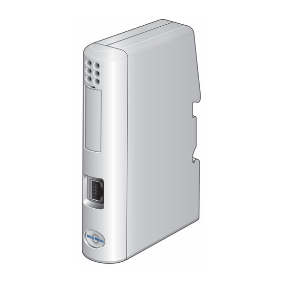
Emerson Micro Motion Quick Start Manual
Ethernet/ip module
Hide thumbs
Also See for Micro Motion:
- Configuration and use manual (212 pages) ,
- User manual (76 pages) ,
- Installation manual (74 pages)
Subscribe to Our Youtube Channel
Summary of Contents for Emerson Micro Motion
- Page 1 Quick Start Guide MMI-20019807, Rev AD January 2019 ® Micro Motion EtherNet/IP Module...
-
Page 2: Set Up The Module With Mvd Direct Connect
Ensure that you have all required components: • Micro Motion EtherNet/IP Module • Power connector • Micro Motion EtherNet/IP Resource CD — Micro Motion EtherNet/IP Module User Manual — EDS file — MicroMotion Ethernet Config Tool • Configuration cable •... -
Page 3: Set Up The Transmitter
January 2019 Quick Start Guide Set up the transmitter Use this procedure only if you are installing the module with a transmitter. Procedure 1. Mount the transmitter and wire it to the sensor and to power. 2. Power up the transmitter. 3. - Page 4 Figure 1-4: Power connections on the EtherNet/IP module A. 24 VDC B. Ground 4. Install the Modbus serial cable between the EtherNet/IP Module and the RS-485 terminals on the transmitter (or the I.S. barrier, if present). Micro Motion EtherNet/IP Module...
- Page 5 January 2019 Quick Start Guide Figure 1-5: Modbus serial connector on the EtherNet/IP module Modbus terminals Pin assignments (EtherNet/IP Module). 5. Set the configuration dip switches on the EtherNet/IP module as follows: • Switches 1–7: Off • Switch 8: On The IP addess is set to 192.168.0.1.
-
Page 6: Modbus Terminals
13. Add the EtherNet/IP Module to the Ethernet network control system. The EDS file is available on the Resource CD, the EtherNet/IP Module (download from Administration page), and the Emerson web site. Postrequisites For more information on transmitter installation and wiring, see your transmitter installation manual. -
Page 7: Led Indicators
January 2019 Quick Start Guide 1.4.2 LED indicators Name Status Description number Module No power applied to the module. Status Solid green The module is operating correctly. (EtherNet) Flashing green Standby. The module has not been initialized. Flashing red Minor fault. The module may or may not be able to recover. - Page 8 Flashing red Missed transactions. Device Power off. Status Flashing red/green Configuration missing or invalid. (Modbus Contact customer service. Serial) Flashing red Contact customer service. Green Initializing. Flashing green Configuration OK. Micro Motion EtherNet/IP Module...
- Page 9 January 2019 Quick Start Guide Quick Start Guide...
- Page 10 Quick Start Guide January 2019 Micro Motion EtherNet/IP Module...
- Page 11 January 2019 Quick Start Guide Quick Start Guide...
- Page 12 © 2019 Micro Motion, Inc. All rights reserved. The Emerson logo is a trademark and service mark of Emerson Electric Co. Micro Motion, ELITE, ProLink, MVD and MVD Direct Connect marks are marks of one of the Emerson Automation Solutions family of companies.


Need help?
Do you have a question about the Micro Motion and is the answer not in the manual?
Questions and answers