Sign In
Upload
Manuals
Brands
Bosch Manuals
Control Panel
D4412
Bosch D4412 Manuals
Manuals and User Guides for Bosch D4412. We have
2
Bosch D4412 manuals available for free PDF download: Operation And Installation Manual, Installation Manual
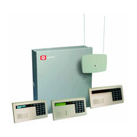
Bosch D4412 Installation Manual (76 pages)
Control/Communicator
Brand:
Bosch
| Category:
Cell Phone
| Size: 6.34 MB
Table of Contents
Table of Contents
2
Introduction
7
Manual Organization
7
Table 1: D6412/D4412 Installation Guide Manual Organization
7
Other Literature Referenced
8
Documentation Conventions
8
Type Styles Used in this Manual
8
Table 2: Other Literature Referenced
8
Tips, Important Notes, Cautions and Warnings
9
FCC Notice
9
Part 15
9
Part 68
9
Overview
10
Specifications
10
Voltage Input
10
Current Requirements
10
Power Outputs
10
Figure 1: System Configuration
10
Battery Discharge/Recharge Schedule
11
Minimum Operating Voltage
11
SDI Bus (Data)
11
Telephone Connections
11
Environmental
11
Arming Stations
11
Compatible Enclosures
11
Compatible Accessories
11
Control/Communicator Configurations
12
SIA Control Panel Standard
12
Standard Features
12
Points
12
Areas and Accounts
12
Communicator
13
Command Centers
13
Keyswitch
13
Alarm Event Memory
13
Event Log
13
Table 3: Compatible Command Centers
13
Emi/Lightning Transient Protection
14
Programming
14
Other Features
14
Control/Communicator Assembly
14
Listings and Approvals
15
Installation
16
Before You Begin
16
Enclosure Options
16
Beginning the Installation
16
Mounting the Enclosure
16
Premises Wiring
16
Installing the Assembly
17
Connecting Earth Ground
17
Figure 2: Enclosure Mounting
17
Closing the Installer Switch
18
Finishing the Installation
18
Earth Ground and Installer Switch
18
Charge the Battery as You Finish
18
Install and Wire Detection Devices
18
Figure 3: Installer Switch
18
Install Modules
19
Make the Telephone Connections
19
Connect the On-Board Points and Command Centers
19
Power up
19
Programming the Panel
19
Check for Fire Alarm Verification
20
Testing the System
20
Power Supply
20
Primary Power
20
Primary (AC) Power Circuit
20
Installing the Transformer
20
Secondary Power
20
Secondary (DC) Power
20
Installing the Battery
21
Replacement
21
Battery Supervision
21
Battery Charging Circuit
21
Battery Discharge/Recharge Schedule
21
System Status LED
22
External Power Supply
22
Power Outputs
22
Circuit Protection
22
Available Power
22
Auxiliary Power
22
Installer's Keypad Connector
22
Figure 4: System Status LED
22
Alarm Power
23
Continuous Power Output
23
Continuous Current Draw
23
Available Power
23
Output Programming
23
Telephone Connections
24
Registration
24
Notification
24
Figure 5: On-Board Outputs
24
Location
25
Phone Cord Connection
25
System Status LED (Red)
25
Dialing Format
25
Figure 6: RJ31X/RJ38X Wiring
25
Figure 7: System Status LED
25
Phone Line Fault
26
Called Party Disconnect
26
Communication Failure
26
Ground Start
26
Figure 8: Ground Start
27
Onboard Sensor Loops
28
Description
28
Two-Wire Smoke Detector Configuration
28
Four-Wire Smoke Detector Configuration
28
Figure 9: Typical Two-Wire Smoke Detector Wiring
28
Sensor Loop 1 Configuration
29
Single Point Configuration (Points 2-8)
29
Figure 10: Typical Four-Wire Smoke Detector Wiring
29
Figure 11: Sensor Loop 1 Wiring
29
Figure 12: Single Point Sensor Loop Wiring
29
Doubled Point Configuration
30
Figure 13: On-Board Doubled Point Sensor Loop Wiring
30
Sensor Loop Response Time
31
Table 4: Point Scan Time/Pulse Count Time Selections
31
Off-Board Sensor Loops
32
SDI Point Expanders
32
Table 5: Off-Board Sensor Loops - Location/Address Assignment
33
DX2010 Point Expander Module
34
DX2010 Overview
34
DX2010 Installation
34
Figure 14: Installing the DX2010 in D203 Enclosure
34
Figure 15: Installing the DX2010 in the Panel's Enclosure
35
Figure 16: Optional Enclosure Mounting Locations for the DX2010
35
DX2010 to Panel SDI Bus Connections
36
Table 6: DX2010 Wire Lengths
36
Figure 17: Wiring the DX2010 to the D6412/D4412
36
DX2010 Auxiliary Output Connections
37
Figure 18: Wiring the DX2010 for External Power Supply
37
Figure 19: Auxiliary Output Connections
37
DX2010 Tamper Input Connections
38
DX2010 Sensor Loop (Point) Connections
38
DX2010 Standard Sensor Loop Wiring
38
Figure 20: DX2010 Tamper Input Wiring
38
Figure 21: DX2010 Sensor Loop Wiring, Single Loop Configuration
38
DX2010 Doubled Sensor Loop (Point) Wiring
39
DX2010 Address Programming
39
Table 7: DX2010 Address 106
39
Table 8: DX2010 Address 107 (for D6412 Only)
39
Table 9: DX2010 Address Settings
39
Figure 22: DX2010 Sensor Loop Wiring, Doubled Loop Configuration
39
DX2010 Status LED
40
Table 10: DX2010 Address Jumper Settings
40
Figure 23: DX2010 DIP Switch Configuration
40
Figure 24: DX2010 Status LED
40
On-Board Outputs
41
Figure 25: PO 1 Wiring
41
Figure 26: PO 2 - PO 4 Wiring
41
Off-Board Outputs
42
Overview
42
DX3010 Octo-Output Module
42
Configuring the DX3010 Octo-Output Module
42
Relay Outputs
42
Installation
43
Figure 27: DX3010 - Control Panel Enclosure Side Mounting
43
Figure 28: Installing the DX3010 in a Remote Enclosure
43
DX3010 to D6412/D4412 SDI Bus Wiring Connections
44
Table 11: DX3010 Wire Lengths
44
Figure 29: Wiring the DX3010 to the D6412/D4412
44
Address Programming
45
Table 12: DX3010 Address Settings
45
Table 13: DX3010 Address Jumper Settings
45
Figure 30: Wiring for External Power Supply
45
Figure 31: DX3010 Address DIP Switches
45
Arming Devices
46
Description
46
Command Centers
46
Assigning the Command Center an Address
46
Table 14: Command Center Address Assignments DIP Switch Settings
46
Figure 32: Command Center DIP Switch Orientation
46
Command Center Installation
47
Table 15: Command Center Wire Lengths
47
Figure 33: Wiring Command Centers to the D6412/D4412
47
D268/D269, D279 Independent Zone Control
48
Figure 34: External Power for Command Centers
48
Keyswitch
49
Keyswitch Description
49
Keyswitch Programming
49
Keyswitch Installation
49
Keyswitch Operation
49
Figure 35: Keyswitches
49
SDI Devices
50
Description
50
Installation
50
Figure 36: SDI Device Wiring
50
DX4010 RS-232 Serial Interface Module
51
Figure 37: External Power for SDI Devices
51
Figure 38: DX4010 RS-232 Serial Interface Module
51
DX4010 Installation
52
DX4010 to D6412/D4412 SDI Bus Wiring Connections
52
RAM IV Direct Connection
52
Figure 39: DX4010 Power Connections
52
Configuration Jumpers
53
Figure 40: Creating a RAM IV Direct Connection
53
Figure 41: DX4010 P2/P3 Jumper Pin Settings
53
Supervision
54
DX4010 Module's DB9 Connector
54
Table 16: DX4010 Address Settings
54
Figure 42: DX4010 DIP Switch Orientation
54
Figure 43: DX4010 DB9 Connector Layout
54
Installer's Keypad and Installer Mode
55
Installer's Keypad Connector
55
Entering the Installer Mode
55
Installer's Passcode
55
Figure 44: Installer's Keypad
55
Service Start/Service End Reports
56
Installer's Menu
56
Press [1] for Bell Test
56
Press [2] for Strobe Test
56
Press [3] for Battery Test
56
Press [4] for Test Report
56
Press [5] for Point Status
56
Figure 45: Installer Switch
56
Press [6] for Output Test
57
Press [7] for RF Menu
57
Adding RF ID Codes
57
Figure 46: Adding RF ID Codes Menu Display
57
Figure 47: RF ID Code Display
57
Testing RF Devices
58
Figure 48: Test RF Devices Display
58
Figure 49: RF Device Test Status Display
58
Viewing/Removing RF ID Codes
59
Press [8] for Keypad Program
59
Press [9] Program Key
59
Figure 50: RF ID Code Display
59
Exiting the Installer's Menu
60
Figure 51: PK32 to D6412/D4412 Connections
60
Press [0] Call for Service Details
61
Installation Label
62
Terminal Quick Reference
64
Troubleshooting
65
Introduction
65
Arming Issues
65
Point Issues
65
Command Center Issues
66
Programming Issues
66
Miscellaneous Issues
66
Appendix A: Approved Applications Compliance Guide
67
Listings and Approvals
67
System Chart
68
System Wiring Diagrams, Issue a
69
Current Rating Chart for Standby Battery Calculations
70
Standby Battery Requirements
71
Standby Battery Calculation for NFPA 72 Fire Alarm Applications
71
Appendix B: SDI Address Chart
71
Advertisement
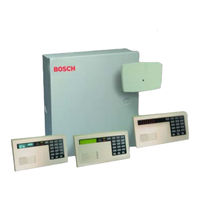
Bosch D4412 Operation And Installation Manual (76 pages)
Brand:
Bosch
| Category:
Control Panel
| Size: 1.55 MB
Table of Contents
Table of Contents
2
1 Introduction
7
Organization
7
Table 1: D6412/D4412 Installation Guide Organization
7
Other Literature Referenced
8
Documentation Conventions
8
Type Styles Used in this Guide
8
Tips, Important Notes, Cautions, and Warnings
8
Table 2: Other Literature Referenced
8
FCC Notice
9
Part 15
9
Part 68
9
2 Overview
10
Specifications
10
Figure 1: System Configuration
10
SIA Control Panel Standard
12
Standard Features
12
Points
12
Areas and Accounts
12
Communicator
12
Command Centers
13
Keyswitch
13
Alarm Event Memory
13
Event Log
13
Emi/Lightning Transient Protection
13
Programming
13
Other Features
13
Table 3: Compatible Command Centers
13
Control Panel Assembly
14
Listings and Approvals
14
3 Installation
15
Before You Begin
15
Enclosure Options
15
Premises Wiring
15
Installing the Assembly
16
Connecting Earth Ground
16
Closing the Installer Switch
16
Figure 2: Enclosure Mounting
16
Figure 3: Installer Switch
16
Finishing the Installation
17
Earth Ground and Installer Switch
17
Charge the Battery as You Finish
17
Install and Wire Detection Devices
17
Install Modules
17
Make the Telephone Connections
17
Connect the On-Board Points and Command Centers
17
Power up
18
Programming the Panel
18
Check for Fire Alarm Verification
18
Testing the System
18
4 Power Supply
19
Primary Power
19
Primary (AC) Power Circuit
19
Installing the Transformer
19
Secondary Power
19
Installing the Battery
19
Replacement
19
Battery Supervision
19
Battery Charging Circuit - Float Charge
20
Battery Discharge/Recharge Schedule
20
System Status LED
20
External Power Supply
20
Table 4: System Status LED Description
20
Figure 4: System Status LED
20
5 Power Outputs
21
Circuit Protection
21
Available Power
21
Auxiliary Power
21
Installer's Keypad Connector
21
Alarm Power
21
Continuous Power Output
21
Continuous Current Draw
21
Output Programming
22
Figure 5: On-Board Outputs
22
6 Telephone Connections
23
Registration
23
Notification
23
Location
23
Phone Cord Connection
23
System Status LED (Red)
23
Dialing Format
23
Figure 6: RJ31X/RJ38X Wiring
23
Phone Line Fault
24
Called Party Disconnect
24
Communication Failure
24
Ground Start
24
Program PO1 for Ground Start
24
Figure 7: Ground Start
25
7 On-Board Sensor Loops
27
Description
27
Two-Wire Smoke Detector Configuration
27
Four-Wire Smoke Detector Configuration
27
Figure 8: Typical Two-Wire Smoke Detector Wiring
27
Figure 9: Typical Four-Wire Smoke Detector Wiring
27
Sensor Loop 1 Configuration
28
Single Point Configuration (Points 2 to 8)
28
Table 5: On-Board Sensor Loops
28
Figure 10: Sensor Loop 1 Wiring
28
Figure 11: Single Point Sensor Loop Wiring
28
Doubled Point Configuration
29
Sensor Loop Response Time
29
Table 6: Point Scan Time/Pulse Count Time Selections
29
Figure 12: On-Board Doubled Point Sensor Loop Wiring
29
8 Off-Board Sensor Loops
31
SDI Point Expanders
31
Table 7: Point Expansion Mapping
31
DX2010 Point Expander Module
33
DX2010 Overview
33
DX2010 Installation
33
Figure 13: Installing the DX2010 in D203 Enclosure
33
Figure 14: Installing the DX2010 in the Panel Enclosure
33
DX2010 to Panel SDI Bus Connections
34
Table 8: DX2010 Wire Lengths
34
Figure 15: Optional Enclosure Mounting Locations for the DX2010
34
Figure 16: Wiring the DX2010 to the D6412/D4412
35
Figure 17: Wiring the DX2010 for External Power Supply
35
DX2010 Auxiliary Output Connections
36
DX2010 Tamper Input Connections
36
DX2010 Sensor Loop (Point) Connections
36
Figure 18: Auxiliary Output Connections
36
Figure 19: DX2010 Tamper Input Wiring
36
DX2010 Address Programming
37
Table 9: DX2010 Address 106
37
Table 10: DX2010 Address 107 (for D6412 Only)
37
Figure 20: DX2010 Sensor Loop Wiring, Single Loop Configuration
37
Figure 21: DX2010 Sensor Loop Wiring, Doubled Loop Configuration
37
DX2010 Status LED
38
Table 11: DX2010 Address Settings
38
Table 12: DX2010 Address Jumper Settings
38
Figure 22: DX2010 DIP Switch Configuration
38
Figure 23: DX2010 Status LED
38
9 On-Board Outputs
39
Figure 24: PO1 Wiring
39
Figure 25: PO2-PO4 Wiring
39
10 Off-Board Outputs
41
Overview
41
DX3010 Octo-Output Module
41
Configuring the DX3010 Octo-Output Module
41
Relay Outputs
41
Installation
42
DX3010 to D6412/D4412 SDI Bus Wiring Connections
42
Table 13: DX3010 Wire Lengths
42
Figure 26: DX3010 - Control Panel Enclosure Side Mounting
42
Figure 27: Installing the DX3010 in a Remote Enclosure
42
Figure 28: Wiring the DX3010 to the D6412/D4412
43
Figure 29: Wiring for External Power Supply
43
Address Programming
44
Table 14: DX3010 Address Settings
44
Table 15: DX3010 Address Jumper Settings
44
Figure 30: DX3010 Address DIP Switches
44
11 0 Arming Devices
45
Description
45
Command Centers
45
Assigning the Command Center an Address
45
Table 16: Command Center Address Assignments DIP Switch Settings
45
Figure 31: Command Center DIP Switch Orientation
45
Command Center Installation
46
Table 17: Command Center Wire Lengths
46
Figure 32: Wiring Command Centers to the D6412/D4412
46
D268/D269, D279 Independent Zone Control
47
Keyswitch
47
Keyswitch Description
47
Keyswitch Programming
47
Figure 33: External Power for Command Centers
47
Keyswitch Installation
48
Keyswitch Operation
48
Figure 34: Keyswitches
48
12 0 SDI Devices
49
Description
49
Installation
49
Figure 35: SDI Device Wiring
49
DX4010 RS-232 Serial Interface Module
50
DX4010 Installation
50
Figure 36: External Power for SDI Devices
50
Figure 37: DX4010 RS-232 Serial Interface Module
50
DX4010 to D6412/D4412 SDI Bus Wiring Connections
51
RAM IV Direct Connection
51
Figure 38: DX4010 Power Connections
51
Figure 39: Creating a RAM IV Direct Connection
51
Configuration Jumpers
52
Supervision
52
DX4010 Module's DB9 Connector
52
Table 18: DX4010 Address Settings
52
Figure 40: DX4010 P2/P3 Jumper Pin Settings
52
Figure 41: DX4010 DIP Switch Orientation
52
Figure 42: DX4010 D89 Connector Layout
52
13 Installer's Keypad and Installer Mode
53
Installer's Keypad Connector
53
Entering the Installer Mode
53
Installer's Passcode
53
Figure 43: Installer's Keypad
53
Service Start/Service End Reports
54
Installer's Menu
54
Press [1] for Bell Test
54
Press [2] for Strobe Test
54
Press [3] for Battery Test
54
Press [4] for Test Report
54
Press [5] for Point Status
54
Figure 44: Installer Switch
54
Press [6] for Output Test
55
Press [7] for RF Menu
55
Figure 45: Adding RF ID Codes Menu Display
55
Figure 46: RF ID Code Display
55
Figure 47: Test RF Devices Display
55
Figure 48: RF Device Test Status Display
55
Press [8] for Keypad Program
56
Figure 49: RF ID Code Display
56
Press [9] Program Key
57
Figure 50: PK32 to D6412/D4412 Connections
57
Exiting the Installer's Menu
58
Press [0] Call for Service Details
58
14 0 Installation Label
59
15 Terminal Quick Reference
61
16 0 Troubleshooting
63
Introduction
63
Arming Issues
63
Point Issues
63
Command Center Issues
64
Programming Issues
64
Miscellaneous Issues
64
Appendix A: Approved Applications Compliance Guide
65
Listings and Approvals
65
System Chart
66
System Wiring Diagrams, Issue a
67
Current Rating Chart for Standby Battery Calculations
68
Standby Battery Requirements
68
Standby Battery Calculation for NFPA 72 Fire Alarm Applications
68
Appendix B: SDI Address Chart
69
Advertisement
Related Products
Bosch DS7200V2-EXP
Bosch D7212GV2
Bosch D6412
Bosch D9412GV2
Bosch D7412GV2
Bosch D7212GV3
Bosch DS6R2
Bosch DS12R
Bosch D7024
Bosch DS7200V2-UK
Bosch Categories
Dishwasher
Washer
Oven
Power Tool
Dryer
More Bosch Manuals
Login
Sign In
OR
Sign in with Facebook
Sign in with Google
Upload manual
Upload from disk
Upload from URL