Sign In
Upload
Manuals
Brands
Bosch Manuals
Control Panel
DS7200V2-EXP
Bosch DS7200V2-EXP Manuals
Manuals and User Guides for Bosch DS7200V2-EXP. We have
1
Bosch DS7200V2-EXP manual available for free PDF download: Installation Manual
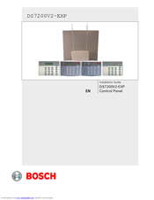
Bosch DS7200V2-EXP Installation Manual (138 pages)
Brand:
Bosch
| Category:
Control Panel
| Size: 2.99 MB
Table of Contents
Zone Expanders
2
Table of Contents
3
Bosch Security Systems, Inc. | 04/12 | F01U253045-02 en
3
Bosch Security Systems, Inc. | 04/12 | F01U253045-02 en
4
Bosch Security Systems, Inc. | 04/12 | F01U253045-02 en
5
Bosch Security Systems, Inc. | 04/12 | F01U253045-02 en
6
1 Introduction
7
Documentation Conventions
7
Scope of Document
7
Table 1: Document Overview
7
Specifications
8
Standard Features
8
Table 2: Control Panel Specifications
8
Control Panel Assembly
9
Listings and Approvals
9
System Options
9
System Batteries
10
Available Power
10
1.10 Installer Keypad/Rps Connector
10
2 System Installation and Setup
11
Control Panel Installation
11
Figure 1: Enclosure Installation
11
Figure 2: Control Panel Board Mounting
12
Figure 3: Standby Battery Connections
12
Figure 4: RAM Backup Battery
13
Figure 5: RJ31X/RJ38X Wiring
13
Figure 6: Ground Start
14
Arming Device Installation
15
Figure 7: Keypad Jumper Plug Configuration
15
Figure 8: Keypad to Control Panel Wiring
15
Table 3: Keypad Address Pin Settings
15
Table 4: Keypad to Control Panel Wire Length
15
Figure 9: Keypad to Control Panel Wiring (External Power Supply)
16
Figure 10: Keyswitch: Tamper Wired Zone Configuration
16
Figure 11: Maintained Keyswitch: Single EOL Resistor Configuration
17
Figure 12: Momentary Keyswitch: Single EOL Resistor Configuration
17
Figure 13: Keyswitch: Zone Doubled Configuration
17
Figure 14: Keyswitch: no EOL Resistor Configuration
17
On-Board Sensor Loop Setup
18
Figure 15: Tamper-Wired Zone Configuration
18
Figure 16: Single Zone Sensor Loop Wiring
19
Figure 17: On-Board Doubled Zone Sensor Loop Wiring
19
Figure 18: Single Zone Sensor Loop Wiring (no EOL)
20
Figure 19: 4-Wire Smoke Detector (Tamper-Wired)
20
On-Board Output Setup
21
Figure 20: 4-Wire Smoke Detector (Single EOL Resistor)
21
Figure 21: PO 1 Wiring (PO 1 Jumper Shorted)
21
Figure 22: PO1 Dry Contact Wiring (no PO 1 Jumper)
21
RF3227E RF Receiver Setup
22
Figure 23: PO 1 Positive Alarm Trigger Wiring
22
Figure 24: PO 2 to PO 4 Wiring
22
Figure 25: RF3227E Address Jumper Settings
22
Off-Board Sensor Loop Setup (DX2010)
23
Figure 26: RF3227E to Control Panel Wiring
23
Figure 27: Standard DX2010 Installation Locations
23
Figure 28: Optional DX2010 Mounting Locations
24
Figure 29: DX2010 to Control Panel Wiring
24
Table 5: DX2010 to Control Panel Wire Length
24
Table 6: DX2010 to External Power Supply Wire Length
24
Figure 30: DX2010 to Control Panel Wiring (External Power Supply)
25
Figure 31: DX2010 Auxiliary Output Wiring
25
Figure 32: DX2010 Tamper Input Wiring
26
Figure 33: DX2010 no Tamper
26
Figure 34: DX2010 Tamper-Wired Zone Wiring
26
Figure 35: DX2010 Single EOL Zone Wiring
27
Figure 36: DX2010 Doubled Zone Wiring
27
Table 7: Control Panel Locations for DX2010 Address 106
27
Table 8: Control Panel Locations for DX2010 Address 107 (DS7240V2 Only)
27
Figure 37: DX2010 DIP Switch Configuration
28
Figure 38: DX2010 Status LED Location
28
Table 9: DX2010 Address Settings
28
Table 10: DX2010 DIP Switch Settings
28
Off-Board Output Setup (DX3010)
29
Figure 39: DX3010 to Control Panel Enclosure Installation
29
Figure 40: DX3010 to Control Panel Wiring
30
Figure 41: DX3010 Output States
30
Figure 42: DX3010 to Control Panel Wiring (External Power Supply)
30
Table 11: DX3010 Wire Lengths
30
Serial Interface Setup (Dx4010I/Dx4010)
31
Figure 43: DX3010 DIP Switch Configuration
31
Table 12: DX3010 Address DIP Switch Settings
31
Table 13: Dx4010I/Dx4010 Wire Lengths
31
Figure 44: Dx4010I to Control Panel Wiring
32
Figure 45: Dx4010I to Control Panel Wiring (External Power Supply)
32
Figure 46: Dx4010I RPS Direct Connect Address Setting
33
Figure 47: Dx4010I Direct Connection
33
Figure 48: DX4010 Direct Connection
34
Figure 49: P1 Jumper Pin Settings
34
Figure 50: DX4010 P2 Jumper Pin Settings
35
Figure 51: RS-232 Device DIP Switch Setting
35
Figure 52: DB9 Connector Layout
35
Table 14: Dx4010I/Dx4010 Diagnostic LED Functions
35
Table 15: DB9 Pin Configuration
35
Network Interface Module (DX4020)
36
Figure 53: Network Communication DIP Switch Setting
36
Figure 54: Standard DX4020 Mounting Locations
36
Figure 55: Optional DX4020 Mounting Locations
36
Figure 56: DX4020 to Control Panel Wiring
37
Figure 57: DX4020 to Control Panel Wiring (External Power Supply)
37
Table 16: DX4020 Wire Lengths
37
Door Access Control Module (DACM)
38
Figure 58: DX4020 Ethernet/Serial Status Leds
38
Table 17: Ethernet/Serial Status LED Functions
38
Table 18: DACM Wire Lengths
38
Figure 59: DACM to Control Panel Wiring
39
Figure 60: DACM to Control Panel Wiring (External Power Supply)
39
2.11 System Power up
40
2.12 System Status LED
40
2.13 Installer Keypad
40
Figure 61: System Status LED
40
Figure 62: Installer Keypad to Control Panel Wiring
40
Table 19: System Status LED Operation
40
2.14 Installer Mode
41
2.15 Installer Menu
41
Figure 63: PK32 to Control Panel Connections
44
2.16 Keypad Programming
45
Table 20: Reserved and Expert Addresses
46
Keypad Test [#][9][1]
47
Table 21: Key/Character Assignments
47
2.18 Always Force Arm
48
3 Control Panel Programming
49
Understanding the Option Parameter Charts
49
Panel-Wide Parameters
50
Table 22: Phone Number Entry Selections
50
Table 23: Personal Dialing Format Configuration
52
Table 24: Report Tone Selections
52
Figure 64: Routing Destination Phone Number Configured for Basic
53
Table 25: Format Field Options
54
Area-Wide Parameters
65
Table 26: Account Number Addresses/Defaults
65
Table 27: Account Number Entry Selections
65
User Interface
68
Table 28: User Configuration
70
Table 29: DS7446KP Keypad Icon Functions
73
Zone Parameters
80
Table 30: Location Configuration Parameters
80
Dacm Configuration
81
Table 31: Default Zone Function Type Selections
83
Table 32: Location Text Addresses/Defaults
84
Output Parameters
86
Table 33: Output Configuration Parameters
86
Table 34: Output Function Types
88
Table 35: Output Mode Options
93
Table 36: Pulse Mode Configuration
95
Table 37: One Shot Mode Configuration
95
Sked Parameters
96
Table 38: Sked Configuration Parameters
96
Data Bus Device Parameters
99
Network Communication
101
Table 39: IP Address Entry Selections
101
3.10 DACM Configuration
105
3.11 Test the System
107
4 Reference Materials
108
Control Panel Events and Reporting Formats
108
Table 40: Control Panel Events and Reporting Formats
109
Troubleshooting
120
Data Bus Address Quick Reference
122
Table 41: Data Bus Address Quick Reference
122
Communication Attempt Tables
123
Table 42: Destination 1 Only
123
Table 43: Destination 2 Only
123
Table 44: Destinations 1 and 2
124
Call for Service Details
125
Table 45: Call for Service Details
125
User Keypad Commands
126
Table 46: System Arming/Disarming Functions
126
Table 47: Other System Functions
126
History Log
127
Table 48: History Log Display Descriptions
127
Table 49: History Log Communication Status Values
127
Standby Battery Calculation
128
Table 50: Standby Battery Calculation
128
Wiring Label
129
Figure 65: DS7200V2 Wiring Label
129
Table 51: Terminal Descriptions
130
4.10 Glossary
131
Advertisement
Advertisement
Related Products
Bosch DS7200V2-UK
Bosch DS6R2
Bosch DS12R
Bosch DS7220V2
Bosch DS7240V2
Bosch D7212GV2
Bosch D6412
Bosch D4412
Bosch D9412GV2
Bosch D7412GV2
Bosch Categories
Dishwasher
Washer
Oven
Power Tool
Dryer
More Bosch Manuals
Login
Sign In
OR
Sign in with Facebook
Sign in with Google
Upload manual
Upload from disk
Upload from URL