Sign In
Upload
Manuals
Brands
Agilent Technologies Manuals
Test Equipment
InfiniiVision DSO6014L
Agilent Technologies InfiniiVision DSO6014L Manuals
Manuals and User Guides for Agilent Technologies InfiniiVision DSO6014L. We have
3
Agilent Technologies InfiniiVision DSO6014L manuals available for free PDF download: User Manual
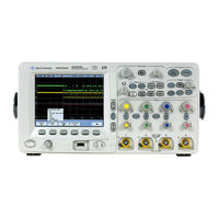
Agilent Technologies InfiniiVision DSO6014L User Manual (428 pages)
InfiniiVision 5000/6000/7000 Series Oscilloscopes
Brand:
Agilent Technologies
| Category:
Test Equipment
| Size: 14.38 MB
Table of Contents
Safety Notices
2
Book Map
3
In this User's Guide
4
Table of Contents
7
Introduction
21
Models Covered in this Manual
22
Specifications and Characteristics
23
Licensed Options
24
Notes
26
Initial Setup
27
Package Contents
28
5000 Series Oscilloscope Package Contents
29
6000A Series Oscilloscope Package Contents
30
6000A Option BAT Oscilloscope Package Contents
31
6000L Series Oscilloscope Package Contents
32
7000A Series Oscilloscope Package Contents
33
Accessories Available
34
Tilt the Oscilloscope up for Easy Viewing
36
To Tilt the 5000 Series Oscilloscope up for Easy Viewing
36
To Tilt the 6000 Series Oscilloscope up for Easy Viewing
37
To Tilt the 7000 Series Oscilloscope up for Easy Viewing
38
To Install the Optional Front Panel Overlay
40
5000 Series Overlay
40
6000 Series Overlay
41
7000 Series Overlay
42
To Mount the Oscilloscope in a Rack
43
To Mount the 5000 or 6000 Series Oscilloscope in a Rack
43
To Mount the 6000L Series Oscilloscope in a Rack
43
To Mount the 7000 Series Oscilloscope in a Rack
46
Ventilation Requirements
47
5000 And 6000A Series Ventilation Requirements
47
6000L Series Ventilation Requirements
47
7000 Series Ventilation Requirements
47
Power Requirements
48
Power-On the 5000/6000/7000 Series Oscilloscope
49
Power-On the Battery-Powered 6000A Series Oscilloscope
49
Caution Indicator
50
AC Adapter for Battery-Powered Oscilloscopes
52
Keys, Softkeys, and the Entry Knob
53
Verifying Basic Oscilloscope Operation
54
Quick Help
55
Quick Help Languages
56
Graphical User Interface Languages
56
Quick Help Updates
56
To Set the Clock
57
To Set up the Screen Saver
58
Using the Analog Channels
59
To Set up the Horizontal Time Base
64
Connecting to the Device under Test
71
Analog Input Impedance (50 Ohm or 1 Mohm)
72
Autoprobe Interface
72
Passive Probes
73
Active Probes
74
Active Probes for 6000 Series 100 Mhz Bandwidth Models
75
Connect the Probes to the Oscilloscope
75
Maximum Input Voltage at Analog Inputs
76
Do Not Float the Oscilloscope Chassis
76
Compensating Passive Probes
77
Calibrating Probes
78
Manually Setting the Probe Attenuation Factor
80
Digital Probes
80
Triggering
81
Triggering - General Information
83
Trigger Mode and Coupling Menu
84
Auto and Normal Trigger Modes
84
Choosing Auto Trigger Mode or Normal Trigger Mode
84
Auto Mode
85
Normal Mode
85
Trigger Level Adjustment
86
Trigger Coupling
87
Trigger Noise Rejection
87
HF Reject
88
LF Reject
89
Noise Rejection
89
Trigger Holdoff
90
Trigger Holdoff Operating Hints
90
To Set Holdoff
90
External Trigger Input
92
2-Channel Oscilloscope External Trigger Input
92
Maximum Voltage at 2-Channel Oscilloscope External Trigger Input
93
4-Channel Oscilloscope External Trigger Input
94
Maximum Voltage at 4-Channel Oscilloscope External Trigger Input
94
Trigger Output
95
Triggers
95
Source Frequency
95
Source Frequency/8
95
Trigger Types
96
CAN Trigger
98
Duration Trigger
102
Qualifier Time Set Softkey
103
Edge Trigger
105
Flexray Setup and Triggering
107
Setup for Flexray Signals
107
Flexray Triggering
108
Glitch or Narrow Pulse Capture
112
Using Peak Detect Mode to Find a Glitch
113
I2C Trigger
115
I2S Trigger
121
LIN Trigger
128
MIL-STD 1553 Setup and Triggering
131
Probing MIL-STD 1553 Signals
131
Setup for MIL-STD 1553 Signals
132
MIL-STD 1553 Triggering
133
Nth Edge Burst Trigger
135
Pattern Trigger
137
Hex Bus Pattern Trigger
139
Pulse Width Trigger
140
Qualifier Time Set Softkey
141
Qualifier Time Set Softkey
142
Sequence Trigger
143
Define the "Find" Stage
145
Define the "Trigger On" Stage
146
Define the Optional "Reset On" Stage
147
Adjust the Trigger Level
149
SPI Trigger
150
Assign Oscilloscope Channels to SPI Signals
151
Set up the Bits in the Serial Data String
155
Resetting All Bits in the Serial Data String to One Value
155
TV Trigger
156
TV Triggering Examples
159
To Trigger on a Specific Line of Video
160
To Trigger on All Sync Pulses
161
To Trigger on a Specific Field of the Video Signal
161
To Trigger on All Fields of the Video Signal
162
To Trigger on Odd or Even Fields
163
UART/RS232 Trigger
166
USB Trigger
170
Displaying
173
Tips for Displaying Waveforms
174
Stabilizing the Display
174
Interpreting the Display
175
Graphic Symbols in Softkey Menus
176
Autoscale
177
How Autoscale Works
177
Undo Autoscale
177
Enabling Fast Debug Autoscale
178
Specifying the Channels Displayed after Autoscale
178
Preserving the Acquisition Mode During Autoscale
178
Pan and Zoom
179
Waveform Intensity and Signal Detail
180
Grid Intensity
181
Infinite Persistence
182
Using Labels
183
Waveform Expansion Reference Point
187
Vectors (Connect the Dots)
187
Freeze Display
188
Antialiasing
189
XGA Video Output
189
Measurements and Math Functions
191
List of Automatic Measurements
192
Making Automatic Measurements
193
Measurement Statistics
194
Measurement Thresholds
197
Measurement Definitions
199
Time Measurements
199
Delay and Phase Measurements
203
Voltage Measurements
205
Overshoot and Preshoot Measurements
211
Cursor Measurements
214
To Make Cursor Measurements
215
Cursor Examples
217
XY Horizontal Mode
220
Math Functions
224
To Use Waveform Math
224
To Perform a Math Function Upon an Arithmetic Operation
225
Math Scale and Offset
225
Units
226
Multiply
227
Add or Subtract
228
Differentiate
230
Integrate
232
Square Root
234
FFT Measurement
236
FFT Operation
238
Enabling Precision Measurements and Math
242
Printing and Saving
243
Printing the Oscilloscope's Display
244
Quick Print
244
To Print the Oscilloscope's Display
245
Options
245
Palette
246
Saving Oscilloscope Data
247
Selecting a Destination for Your Saved Data
248
Selecting a File Name
249
Saving Waveform Trace and Oscilloscope Setup
250
Display Image and Waveform Data File Formats
250
Choosing Save Settings
251
To Save a Waveform And/Or Setup to a USB Mass Storage Device
255
To Save a Waveform And/Or Setup to the Oscilloscope's Internal Memory
256
To Recall Waveform Trace And/Or Oscilloscope Setup
256
File Explorer
257
Acquisition Modes
261
To Start and Stop an Acquisition
262
To Make a Single Acquisition
264
Acquisition Modes
265
At Slower Sweep Speeds
265
Selecting the Acquisition Mode
265
Normal Mode
265
Peak Detect Mode
266
High Resolution Mode
266
Averaging Mode
267
Realtime Sampling Option
269
Segmented Memory
271
Using Segmented Memory
271
Web Interface
275
Setting up the Oscilloscope's LAN Connection
276
To Establish a LAN Connection
276
To Establish a LAN Connection (6000L Series)
277
Stand-Alone (Point-To-Point) Connection to a PC
278
Accessing the Web Interface
280
Browser Web Control
281
Remote Front Panel
281
Remote Programming
283
Remote Programming with Agilent IO Libraries
284
Get Image
285
Identification Function
286
Instrument Utilities
287
Setting a Password
288
Serial Decode/Lister
291
Serial Decode
292
Lister
293
Serial Decode Lister
293
CAN Serial Decode
295
Interpreting CAN Decode
298
CAN Totalizer
299
Interpreting CAN Lister Data
301
Flexray Serial Decode
302
Interpreting Flexray Frame Decode
303
Flexray Totalizer
304
Interpreting Flexray Lister Data
305
I 2 C Serial Decode
306
Interpreting I 2 C Decode
308
Interpreting I 2 C Lister Data
309
I 2 S Serial Decode
310
Interpreting I 2 S Decode
312
Interpreting I 2 S Lister Data
313
LIN Serial Decode
314
Interpreting LIN Decode
317
Interpreting LIN Lister Data
319
MIL-STD 1553 Serial Decode
320
Interpreting MIL-STD 1553 Decode
321
Viewing MIL-STD 1553 Data in the Lister
322
SPI Serial Decode
323
Interpreting SPI Decode
327
Interpreting SPI Lister Data
328
UART/RS232 Serial Decode
329
Interpreting UART/RS232 Decode
333
UART/RS232 Totalizer
334
Interpreting UART/RS232 Lister Data
335
Mask Test
337
To Create a Mask from a "Golden" Waveform (Automask)
338
Troubleshooting Mask Setup
339
Setup Options
340
Run until
340
On Error
340
Source Lock
341
Mask Test Trigger Output
342
Mask Statistics
343
Reset Statistics
344
Transparent
344
To Manually Modify a Mask File
345
Building a Mask File
348
Controls and Connectors
351
Front Panel
352
5000/6000 Series Front Panel (4-Channel)
352
5000/6000 Series Front Panel (2-Channel, Differences Only)
353
6000L Series Front and Rear Panel
354
7000 Series Front Panel (4-Channel)
355
7000 Series Front Panel (2-Channel, Differences Only)
356
Front Panel Control and Connector Descriptions
357
Do Not Connect a Host Computer to the Oscilloscope's USB Host Port
357
Rear Panel
362
5000 Series Rear Panel (4-Channel)
362
5000 Series Rear Panel (2-Channel)
363
6000 Series Rear Panel (4-Channel)
364
6000 Series Rear Panel (2-Channel)
365
6000 Series Option BAT Rear Panel (4-Channel)
366
7000 Series Rear Panel (4-Channel)
367
7000 Series Rear Panel (2-Channel)
368
Rear Panel Control and Connector Descriptions
369
Digital Channels
371
To Connect the Digital Probes to the Device under Test
372
Probe Cable for Digital Channels
372
Acquiring Waveforms Using the Digital Channels
375
To Display Digital Channels Using Autoscale
376
Example
376
Interpreting the Digital Waveform Display
378
To Change the Displayed Size of the Digital Channels
379
To Switch a Single Channel on or off
379
To Switch All Digital Channels on or off
379
To Switch Groups of Channels on or off
379
To Change the Logic Threshold for Digital Channels
380
To Reposition a Digital Channel
380
To Display Digital Channels as a Bus
381
Digital Channel Signal Fidelity: Probe Impedance and Grounding
385
Input Impedance
385
Probe Grounding
387
Best Probing Practices
388
To Replace Digital Probe Leads
389
Utilities
391
To Restore the Oscilloscope to Its Default Configuration
392
To Perform Service Functions
393
User Calibration
394
Self Test
397
Reference
399
About Oscilloscope
400
Software and Firmware Updates
400
Installed Licenses
400
Upgrading to an MSO
401
Secure Environment Mode Option
402
Measurement Category
403
Measurement Category Definitions
403
Transient Withstand Capability
404
Maximum Input Voltage at Analog Inputs and 2-Channel External Trigger Input
404
Maximum Input Voltage at Digital Channels
404
Environmental Conditions
405
Using the 10 Mhz Reference Clock
406
Sample Clock and Frequency Counter Accuracy
406
Supplying an External Timebase Reference
406
To Supply a Sample Clock to the Oscilloscope
406
Maximum Input Voltage at 10 Mhz REF Connector
406
To Synchronize the Timebase of Two or more Instruments
408
To Clean the Oscilloscope
408
Binary Data (.Bin) Format
409
Binary Data in MATLAB
409
Binary Header Format
410
Example Program for Reading Binary Data
413
Examples of Binary Files
414
CSV and ASCII XY Files
417
Acknowledgements
418
To Check Warranty and Extended Services Status
418
To Return the Instrument
419
Contact Us
420
Index
421
I2 Serial Decode
423
Advertisement
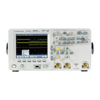
Agilent Technologies InfiniiVision DSO6014L User Manual (371 pages)
6000 Series
Brand:
Agilent Technologies
| Category:
Test Equipment
| Size: 8.19 MB
Table of Contents
Safety Notices
3
Table of Contents
10
Getting Started
20
To Inspect Package Contents
22
To Adjust the 6000A Series Handle
27
To Mount the Oscilloscope in a Rack
28
To Mount the 6000A Series Oscilloscope in a Rack
28
To Mount the 6000L Series Oscilloscope in a Rack
28
Ventilation Requirements
31
To Power-On the Oscilloscope
32
AC-Powered 6000 Series
32
Battery-Powered 6000A Series
32
The Remote Interface
37
To Establish a LAN Connection (6000A Series)
38
To Establish a LAN Connection (6000L Series)
39
To Establish a Point-To-Point LAN Connection
41
To Use the Web Interface
42
Controlling the Oscilloscope Using a Web Browser
43
Setting a Password
45
Scrolling and Monitor Resolution
48
Identify Function
48
To Connect the Oscilloscope Probes
50
To Verify Basic Oscilloscope Operation
51
To Compensate the Oscilloscope Probes
53
To Calibrate the Probes
54
Passive Probes Supported
54
Active Probes Supported
55
By 300 Mhz, 500 Mhz, and 1 Ghz Bandwidth Models
55
By 100 Mhz Bandwidth Models
56
Using Quick Help
57
Quick Help Languages
58
Front-Panel Controls
60
6000L Series Oscilloscope Controls
61
Front and Rear Panel Controls and Connectors
62
6000A Series Oscilloscope Front-Panel Controls
65
Conventions
66
Graphic Symbols in Softkey Menus
66
4-Channel 6000A Series Oscilloscope Front Panel
67
Front Panel Controls
68
2-Channel 6000A Series Oscilloscope Front Panel (Differences Only)
73
Interpreting the Display
74
6000A Series Front-Panel Operation
75
To Adjust the Waveform Intensity
75
To Adjust the Display Grid (Graticule) Intensity
75
To Start and Stop an Acquisition
76
To Make a Single Acquisition
77
To Pan and Zoom
78
Choosing Auto Trigger Mode or Normal Trigger Mode
79
Using Autoscale
79
To Set the Probe Attenuation Factor
80
Using the Analog Channels
82
To Set up the Horizontal Time Base
87
To Make Cursor Measurements
94
To Make Automatic Measurements
95
Using Labels
96
To Print the Display
100
To Set the Clock
100
To Set up the Screen Saver
101
To Set the Waveform Expansion Reference Point
102
To Perform Service Functions
103
User Calibration
103
Self Test
106
About Oscilloscope
106
To Restore the Oscilloscope to Its Default Configuration
107
Viewing and Measuring Digital Signals
110
To Connect the Digital Probes to the Circuit under Test
111
Acquiring Waveforms Using the Digital Channels
114
To Display Digital Channels Using Autoscale
115
Example
115
Interpreting the Digital Waveform Display
117
To Switch All Digital Channels on or off
118
To Switch Groups of Channels on or off
118
To Switch a Single Channel on or off
118
To Change the Displayed Size of the Digital Channels
119
To Reposition a Digital Channel
119
To Change the Logic Threshold for Digital Channels
120
To Display Digital Channels as a Bus
121
Triggering the Oscilloscope
126
Selecting Trigger Modes and Conditions
129
To Select the Mode and Coupling Menu
129
Trigger Modes: Normal and Auto
130
To Select Trigger Coupling
132
To Select Trigger Noise Rejection and HF Rejection
132
To Set Holdoff
133
The External Trigger Input
135
2-Channel Oscilloscope External Trigger Input
135
4-Channel Oscilloscope External Trigger Input
137
Trigger Types
138
To Use Edge Triggering
139
Trigger Level Adjustment
140
To Use Pulse Width Triggering
141
Qualifier Time Set Softkey
143
To Use Pattern Triggering
144
To Use CAN Triggering
146
To Use Duration Triggering
150
Qualifier Time Set Softkey
152
To Use Flexray Triggering
153
Modes of BUSDOCTOR Control/Operation
153
Setting up the Oscilloscope and BUSDOCTOR 2
154
Triggering on Flexray Frames, Times, or Errors
158
To Use I2C Triggering
162
To Use Nth Edge Burst Triggering
168
To Use LIN Triggering
170
To Use Sequence Triggering
173
Define the Find: Stage
175
Define the Trigger On: Stage
176
Define the Optional Reset On: Stage
178
Adjust the Trigger Level
179
To Use SPI Triggering
180
Assign Source Channels to the Clock, Data, and Frame Signals
182
Set up the Number of Bits in the Serial Data String and Set Values for those Data Bits
185
Resetting All Bits in the Serial Data String to One Value
185
To Use TV Triggering
185
Example Exercises
189
To Trigger on a Specific Line of Video
189
To Trigger on All Sync Pulses
191
To Trigger on a Specific Field of the Video Signal
192
To Trigger on All Fields of the Video Signal
193
To Trigger on Odd or Even Fields
194
To Use USB Triggering
197
The Trigger out Connector
199
Triggers
199
Source Frequency
199
Source Frequency/8
199
Making Measurements
200
To Use the XY Horizontal Mode
201
Math Functions
206
Math Scale and Offset
207
Multiply
208
Subtract
210
Differentiate
212
Integrate
214
FFT Measurement
217
FFT Operation
219
Square Root
224
Cursor Measurements
226
To Make Cursor Measurements
226
Cursor Examples
230
Automatic Measurements
233
To Make an Automatic Measurement
234
To Set Measurement Thresholds
235
Time Measurements
237
Delay and Phase Measurements
241
Voltage Measurements
244
Overshoot and Preshoot Measurements
249
Displaying Data
252
Pan and Zoom
253
To Pan and Zoom a Waveform
254
To Set the Waveform Expansion Reference Point
254
Antialiasing
255
Using the XGA Video Output
255
Display Settings
256
Infinite Persistence
256
Grid Intensity
257
Vectors (Connect the Dots)
257
Varying the Intensity to View Signal Detail
258
Acquisition Modes
260
At Slower Sweep Speeds
260
Selecting the Acquisition Mode
260
Normal Mode
261
Peak Detect Mode
261
High Resolution Mode
261
Averaging Mode
262
Realtime Sampling Option
264
Using Serial Decode
266
To Decode I 2 C Data
267
To Decode SPI Data
271
To Decode CAN Data
276
CAN Totalizer
281
To Decode LIN Data
283
To Decode Flexray Data
289
Flexray Totalizer
293
To Reduce the Random Noise on a Signal
295
HF Reject
295
LF Reject
296
Noise Rejection
296
To Capture Glitches or Narrow Pulses with Peak Detect and Infinite Persistence
297
Using Peak Detect Mode to Find a Glitch
298
How Autoscale Works
300
Undo Autoscale
300
Specifying the Channels Displayed after Autoscale
301
Preserving the Acquisition Mode During Autoscale
301
Saving and Printing Data
302
To Configure Printing
303
Selecting a Print File Format
303
Selecting Print Options
306
Print Palette
306
To Print the Display to a File
307
To Print the Display to a USB Printer
308
Supported Printers
309
Printers
309
Secure Environment Mode Option
311
Saving and Recalling Traces and Setups
313
To Autosave Traces and Setups
314
To Save Traces and Setups to Internal Memory or to Overwrite an Existing USB Mass Storage Device File
315
Device
316
To Save Traces and Setups to a New File on the USB Mass Storage Device
316
To Recall Traces and Setups
318
To Use the File Explorer
319
Reference
322
Upgrading to an MSO or Adding Memory Depth
323
Software and Firmware Updates
323
To Set up the I/O Port
324
Using the 10 Mhz Reference Clock
325
Sample Clock and Frequency Counter Accuracy
325
Supplying an External Timebase Reference
325
To Supply a Sample Clock to the Oscilloscope
325
To Synchronize the Timebase of Two or more Instruments
327
To Check Warranty and Extended Services Status
327
To Return the Instrument
328
To Clean the Oscilloscope
328
Digital Channel Signal Fidelity: Probe Impedance and Grounding
329
Input Impedance
329
Probe Grounding
331
Best Probing Practices
333
To Replace Digital Probe Leads
334
Binary Data (.Bin)
335
Binary Data in MATLAB
335
Binary Header Format
335
Example Program for Reading Binary Data
339
Examples of Binary Files
340
Characteristics and Specifications
342
6000A Series and 6000L Series Environmental Conditions
343
Overvoltage Category
343
Pollution Degree
343
Pollution Degree Definitions
343
6000A Series and 6000L Series Measurement Category
344
Measurement Category
344
Measurement Category Definitions
344
6000A Series and 6000L Series Transient Withstand Capability
345
6000A Series Oscilloscope Specifications
346
6000A Series Oscilloscope Characteristics
347
6000L Series Specifications and Characteristics
357
Performance Characteristics
357
Trigger System
359
Measurement Features
360
General Characteristics
361
Power Requirements
362
Environmental Characteristics
362
Ordering Information
363
Index
364
Agilent Technologies InfiniiVision DSO6014L User Manual (174 pages)
Oscilloscopes
Brand:
Agilent Technologies
| Category:
Measuring Instruments
| Size: 11.5 MB
Table of Contents
Table of Contents
7
Figures
11
Tables
15
Characteristics and Specifications
17
6000A Series and 6000L Series Environmental Conditions
18
Overvoltage Category
18
Pollution Degree
18
Pollution Degree Definitions
18
6000A Series and 6000L Series Measurement Category
19
Measurement Category
19
Measurement Category Definitions
19
6000A Series and 6000L Series Transient Withstand Capability
20
6000A Series Oscilloscope Specifications
21
Table 1. Warranted Specifications
21
6000A Series Oscilloscope Characteristics
22
Table 2. Characteristics
22
6000L Series Specifications and Characteristics
32
Performance Characteristics
32
Testing Performance
39
List of Test Equipment
40
Table 3 List of Test Equipment
40
Fluke MET/CAL Procedures
41
Table 4 Conventions
41
Table 5 Materials Required to Construct the Test Connectors
42
To Construct the Test Connector (for Use with MSO Models Only)
42
Figure 1 Constructing the 8-By-2 Connector
43
To Test Digital Channels (MSO Models Only)
44
To Verify Digital Channel Threshold Accuracy (MSO Models Only)
45
Verifying Test Results
45
What to Test
45
When to Test
45
Table 6 Equipment Required to Test Digital Channel Threshold Accuracy
46
Figure 2. Setting up Equipment and Test Connector for the
47
Table 7 Threshold Accuracy Voltage Test Settings
48
To Verify Voltage Measurement Accuracy
49
Figure 3. Connect Equipment
52
Figure 4. Using a Blocking Capacitor to Reduce Noise
53
To Verify Bandwidth
54
Table 10 Equipment Required to Verify Bandwidth
55
Figure 5. Connect Equipment
56
To Verify Horizontal Dt Accuracy
59
To Verify Trigger Sensitivity
61
Table 12 Equipment Required to Verify Trigger Sensitivity
62
Figure 6 Connect Equipment
63
Test Internal Trigger Sensitivity (All Models)
63
Test External Trigger Sensitivity (2-Channel Models)
65
Figure 7. Connect Equipment
66
Test External Trigger Sensitivity (4-Channel Models)
68
Figure 8 Connect Equipment
69
Agilent 6000 Series Oscilloscopes Performance Test Record
71
Calibrating and Adjusting
73
To Perform User Cal
75
User Calibration
75
Figure 9 User Calibration Cable for 2-Channel Oscilloscope
76
Figure 10 User Calibration Cable for 4-Channel Oscilloscope
77
User Cal Status
78
Troubleshooting
79
Solving General Problems with the Oscilloscope
80
Troubleshooting the Oscilloscope
83
Equipment Required for Troubleshooting
84
Table 13. Equipment Required to Troubleshoot the
84
To Check out the Oscilloscope
84
Figure 11 6000A Series Start up Sequence
85
Figure 12 6000L Series LED Indicators
86
To Verify Basic Oscilloscope Operation
87
Figure 13 Example Pulses
88
To Compensate the Analog Probes
88
Troubleshooting Flowchart
90
To Check the 6000A Series Oscilloscope Power Supply
91
Figure 14 System Board Test Points
92
To Check the 6000L Series Oscilloscope Power Supply
94
Table 14 System Board Test Points
96
To Check the 6000A Series or 6000L Series System Board
96
Table 15 Display Signals on the System Board
97
To Check the 6000A Series Display
97
To Check the 6000L Series Display Output
97
Figure 15. Location of the Fan Connector
98
To Check the Fan
98
To Run the Internal Self-Tests
99
To Verify Default Setup
99
Figure 16 Default Setup Screen
100
Replacing 6000A Assemblies
101
Figure 17 Removing the Cabinet
103
To Remove the Cabinet
103
Figure 18 Removing Handle
104
To Remove the Handle
104
Figure 19 Installing the Hinged Storage Lid
105
To Remove the Storage Lid
105
Figure 20 Removing the Intensity Knob and T6 Screws
106
To Remove the Front Panel Assembly
106
Figure 22. Removing the Front Panel
107
Front Panel
109
To Remove the Keyboard Assembly
109
Figure 23. Removing the Keyboard Assembly
110
Keyboard
110
To Remove the Display Assembly
112
Figure 24. Removing the Main Shield and Disconnecting the Display
113
Display Assembly
114
Figure 25 Removing the Display Assembly
114
Figure 26 Installing the Display
115
Figure 27 Opening the Backlight Inverter Shield
116
To Remove the Backlight Inverter Board and E-Field Shield
116
Figure 28 Removing the Backlight Inverter
117
Figure 29 Removing the Backlight Inverter Shield
118
Figure 30 Closing the Shield
119
Figure 31. Release Display Mount Latches
120
To Remove the LCD, Gasket, and Protective Lens from the Display Mount
120
Figure 32 Removing the LCD, Gasket, and Protective Lens
121
Figure 33 Latch over Face of Sheet Metal Housing
122
Figure 34 Release Hook Legs from Deck
123
To Remove the Power Supply Shield
123
Figure 35 Dielectric Insulator Tape
124
Figure 36. Proper Angles for Tabs and Hook Legs
125
Figure 37 Tilt to Insert Tabs
125
Figure 38 Insert Hook Legs and Lock in Place
126
Figure 39. Removing the Power Supply
127
Power Supply Shield
127
To Remove the Power Supply
127
Figure 40. Removing the Power Shaft Latch
128
To Remove the Power Shaft
128
AC Input Board
129
Figure 41 Removing the AC Input Board
129
To Remove the AC Input Board
129
To Remove the Fan
130
Figure 43 Removing the Fan
131
To Remove the System Board
132
Figure 44 Preparing to Remove the System Board
133
Figure 45. Removing the System Board
134
Replacing 6000L Assemblies
137
Figure 46 Removing the Cover
139
To Remove the Bottom Cover
139
Figure 47 Removing the Intensity Knob
140
To Remove the Front Panel Assembly
140
Figure 21. Disconnecting Ribbon Cable and Releasing Tab Retainers
141
To Remove the System Board
142
Figure 49 Preparing to Remove the System Board
143
Figure 50. Avoid Damage to Thermal Pads
143
Figure 51. Removing the Power Supply
144
To Remove the Power Supply
144
Figure 52 Removing the Fan
146
To Remove the Fan
146
Figure 53 Installing the Fan
147
To Remove the AC Power Input Assembly
148
Figure 54. Removing the AC Power Input Board
149
Figure 55 Removing the Power Shaft
150
To Remove the Power Shaft
150
Replaceable Parts for the Agilent 6000A Oscilloscope
151
Direct Mail Order System
152
Listed Parts
152
Ordering Replaceable Parts
152
Unlisted Parts
152
Exchange Assemblies
153
Exploded Views
154
Replaceable Parts List
156
Table 1 Replaceable Parts
156
Table 2 Power Cords
161
Replaceable Parts for the Agilent 6000L Oscilloscope
163
Direct Mail Order System
164
Listed Parts
164
Ordering Replaceable Parts
164
Unlisted Parts
164
Exchange Assemblies
165
Exploded Views
166
Replaceable Parts List
168
Table 3 Replaceable Parts
168
Table 4 Power Cords
169
Index
171
Advertisement
Advertisement
Related Products
Agilent Technologies InfiniiVision DSO6032A
Agilent Technologies InfiniiVision DSO6012A
Agilent Technologies InfiniiVision DSO6052A
Agilent Technologies InfiniiVision DSO6014A
Agilent Technologies InfiniiVision DSO6034A
Agilent Technologies InfiniiVision DSO6054A
Agilent Technologies InfiniiVision DSO6054L
Agilent Technologies DSO6054A/L
Agilent Technologies DSO6014A/L
Agilent Technologies DSO6104A/L
Agilent Technologies Categories
Measuring Instruments
Laboratory Equipment
Test Equipment
Water Pump
Power Supply
More Agilent Technologies Manuals
Login
Sign In
OR
Sign in with Facebook
Sign in with Google
Upload manual
Upload from disk
Upload from URL