Sign In
Upload
Manuals
Brands
ADIC Manuals
Controller
Scalar
ADIC Scalar Manuals
Manuals and User Guides for ADIC Scalar. We have
1
ADIC Scalar manual available for free PDF download: Reference Manual
ADIC Scalar Reference Manual (340 pages)
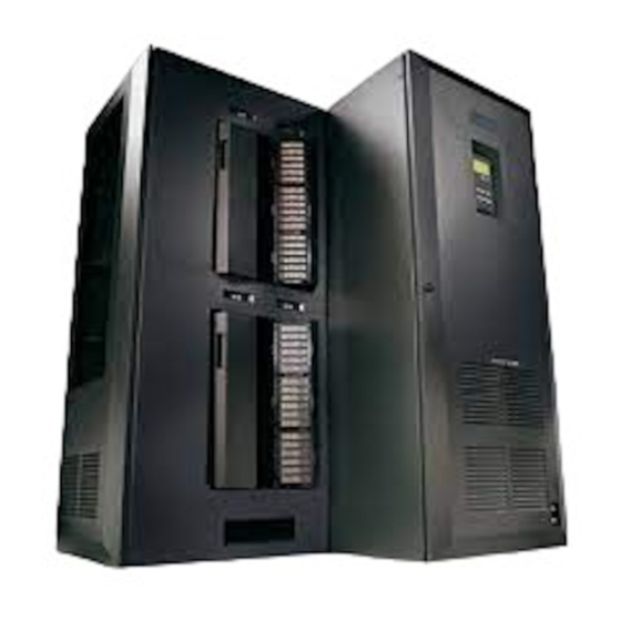
Distributed Library Controller
Brand:
ADIC
| Category:
Controller
| Size: 7.27 MB
Table of Contents
Table of Contents
11
Introduction
33
Intended Audience
33
Organization
33
Explanation of Symbols and Conventions
34
Associated Documents
34
Customer Assistance
35
Technical Assistance
35
Contacting Support
35
Description
37
System Description
38
Figure 2-1 Client Connection
38
Logical Library Concepts
39
Figure 2-2 Physical Libraries Connected to the Scalar DLC
39
PC System Requirements
40
Figure 2-3 Partitions and Logical Libraries
40
Figure 2-4 Clients and Logical Libraries
40
Cluster Solution Requirements
41
Table 2-1 SCSI and Fibre Channel Adapters
41
Tape Library Requirements
42
Operating Mode
42
Firmware Version
43
Remote Browser Requirements
43
Table 2-2 Required Firmware Version
43
Graphical User Interface
44
Command Line Interface
45
Service and Maintenance Alerts
46
Configuration
47
Autostart Installation
48
Scalar DLC Management GUI
50
Resizing Windows and Panes
50
Figure 3-2 about Scalar DLC
50
Table 3-2 Scalar DLC Task Bar Icons
50
Browser Pre-Installation
51
Figure 3-3 ADIC Scalar DLC Home Page
51
Java Plug-In
52
Figure 3-4 Tools and Utilities Page
52
Launch the Management GUI from a Browser
53
Firewall and Proxy Issues
53
Figure 3-5 Scalar DLC GUI Logon Dialog
53
Launch the Management GUI as an Application
54
Figure 3-6 Host Connection Window
54
Configuration
55
Automatic Configuration
55
Figure 3-7 Configuration Window
55
Manual Configuration
56
Advanced Configuration
56
Table 3-3 Scalar DLC Software System Name
56
Rescan SCSI Bus
57
Create Partitions
57
Create a Logical Library
57
Assign Partitions to a Library
57
Create Mailbox
57
Create Client
58
Initialize the Logical Library
58
Create Pool
58
Configure Clean Manager
59
Assign Drives to Cartridges
59
Define Drives and Cartridges
59
Configure Additional Libraries
59
Additional Configuration
59
Configure Email Notifications
59
Update ATAC Settings
60
Main Menu Operations
61
Main Menu Bar
62
Screen Refresh Icon
62
Connection
62
Figure 4-1 Main Menu Bar
62
Table 4-1 Screen Refresh Icon
62
Wizards
63
Create Configuration
63
Table 4-2 Connections
63
Figure 4-2 Select Physical Library
64
Figure 4-3 Select Logical Library
64
Table 4-4 Select Physical Library Areas
64
Figure 5-3 Library
65
Figure 4-5 Select Media
66
Figure 4-6 Select Library Prototype
66
Table 4-7 Select Media
66
Table 4-8 Select Library Prototype
66
Figure 4-7 Select Mailbox
67
Figure 4-8 Select Client
67
Table 4-9 Select Mailbox Areas
67
Assign Partitions
69
Figure 4-10 Configuration Complete
69
Figure 4-11 Partitions Contained
69
Table 4-12 Configuration Complete Areas
69
Figure 4-12 Partitions Not Contained
70
Figure 4-13 Partition List
70
Table 4-13 Partition Areas
70
Table 4-14 Partition List Areas
70
Create Ticket
71
Create Rule
76
Figure 4-20 Ticket Summary
76
Table 4-21 Ticket Summary Areas
76
Table 4-22 Event Specification
77
Figure 4-21 Rule Name
80
Table 4-23 Rule Name Areas
80
Figure 4-22 Rule Event
81
Figure 4-27 Rule Email
84
Extended Service
85
Registration Information
85
Figure 4-28 Rule Summary
85
Table 4-30 Rule Summary
85
Connect to RMU
87
Figure 4-30 Connect to RMU
87
Table 4-31 Registration Info
87
View Log
88
Figure 4-32 View Log: Advanced Mode
89
Table 4-32 View Log: Standard Mode
89
Table 4-33 View Log: Advanced Mode
89
Figure 4-33 Log Message Detail
90
Table 4-34 Log Message Detail
90
Help
91
Figure 4-34 Scalar DLC Software Version Code
91
Table 4-35 Help Contents
91
GUI Log
92
Figure 4-35 GUI Log
92
Table 4-36 GUI Log
92
GUI Tabs
93
Figure 5-1 GUI Tabs: Working Areas
93
Table 5-1 Tree Objects
93
Table 5-2 Logical Library States
95
Table 5-3 Physical Library States
95
Table 5-4 Robot States
95
Table 5-6 Storage Slots
96
Table 5-7 Mailbox Slots
96
Table 5-8 Drive Slots
97
Table 5-10 Operational Buttons
97
Tabs Structure
98
Library Tab
99
Library
100
Table 5-12 Library Properties
100
Cartridges
101
Figure 5-4 Cartridges
102
Home Position
103
Figure 5-5 Multiple Mailbox Selection
103
Table 5-13 Cartridge Properties and Buttons
103
Drag and Drop Operations
104
Move Cartridge to Element
104
Cartridge State
105
Pool
107
Figure 5-7 Pool
107
Mailbox
108
Figure 5-8 Mailbox
108
Drives
109
Table 5-16 Mailbox Properties and Buttons
109
Figure 5-9 Drives
110
Table 5-17 Drives Properties and Buttons
111
Configuration Tab
112
Logical Tab
112
Figure 5-10 Logical Controller
112
Library
113
Figure 5-11 Logical Library
113
Partition
114
Table 5-19 Logical Library Properties and Buttons
114
Figure 5-12 Logical Partition
115
Pool
116
Figure 5-14 Pool
116
Assign Media to Pool
117
Table 5-21 Pool Properties and Buttons
117
Cartridge
118
Figure 5-15 Assign/Unassign Cartridges to Pool
118
Figure 5-16 Normal Cartridge
119
Mailbox
121
Figure 5-17 Foreign Cartridge
121
Figure 5-18 Mailbox
122
Assign Slots to Mailbox
123
Storage Slot
123
Figure 5-19 Assign/Unassign Slots to Mailbox
123
Figure 5-20 Storage Slot
124
Mailbox Slot
125
Figure 5-21 Mailbox Slot
125
Drive
126
Table 5-25 Mailbox Slot Properties and Buttons
126
Figure 5-22 Drive
127
Create Library
128
Table 5-26 Drive Properties and Buttons
128
Assign Partition
129
Figure 5-23 Logical Library Creation
129
Create Pool
130
Figure 5-24 Partition Assign
130
Figure 5-25 Pool Creation
131
Create Mailbox
132
Figure 5-26 Mailbox Creation
132
Physical Tab
133
Table 5-30 Mailbox Creation Properties and Buttons
133
Figure 5-27 Physical Controller
134
Library
135
Figure 5-28 Physical Library Properties
135
Figure 5-29 Media Rules
137
Table 5-33 Media Rules
137
Robot
139
Figure 5-32 Robot Online
139
Offline Cartridge
140
Figure 5-33 Robot Offline
140
Figure 5-34 Offline Cartridges
141
Figure 5-35 Offline Cartridge
142
Table 5-35 Offline Cartridges
142
Storage Slots
143
Table 5-36 Offline Cartridge Properties
143
Mailboxes
144
Figure 5-36 Physical Storage Slots
144
Drives
145
Figure 5-37 Physical Mailboxes
145
Partition
146
Figure 5-38 Physical Drives
146
Figure 5-39 Physical Partition
147
Table 5-40 Physical Partition Properties and Buttons
147
Create Partition
148
Figure 5-40 Partition Creation
148
Users Tab
149
Table 5-42 Users Icons
149
Table 5-43 User Privileges
150
Figure 5-41 User Controller
151
User
152
Figure 5-42 User
152
Create User
153
Figure 5-43 User Creation
154
Clients Tab
155
Das
155
Table 5-47 Client Icons
155
DAS Client
156
Figure 5-44 das Interface Pane
156
Figure 5-45 das Client Properties
157
Figure 5-46 das Client Drives
159
Table 5-50 das Client Drives
159
Figure 5-47 Define Drives
160
Figure 5-48 das Client Volsers
161
Table 5-51 das Client Volsers
161
Figure 5-49 Reserve/Define Volser Range
162
Figure 5-50 das Client Aliasing
163
Table 5-52 das Client Aliasing
163
Create das Client
164
Figure 5-51 das Client Creation
164
Scsi
165
SCSI Client
166
Figure 5-52 SCSI Pane
166
Figure 5-53 SCSI Client Properties
167
Figure 5-54 SCSI Client Mode
169
Table 5-56 SCSI Client Mode Parameters and Buttons
170
Figure 5-55 SCSI Client Drives
171
Figure 5-56 SCSI Client I/E Slots
172
Create SCSI Client
173
Figure 5-57 SCSI Client Storages
173
Robar
175
Figure 5-59 ROBAR Interface Pane
175
ROBAR Client
176
Create ROBAR Client
177
Table 5-62 ROBAR Client Properties and Buttons
177
Figure 5-61 ROBAR Client Creation
178
SCSI Target Tab
179
Port
180
Table 5-64 SCSI Target Icons
180
Figure 5-62 Port: SCSI
181
Target
182
Figure 5-63 Port: Fibre Channel
182
Figure 5-64 SCSI Target
183
Logical Unit Number (LUN)
184
Create Target
186
Figure 5-66 SCSI Target Creation
186
Create LUN
187
Figure 5-67 SCSI LUN Creation
188
Events Tab
189
Queue Tab
189
Figure 5-68 Queue Tab
190
Monitoring Tab
191
Figure 5-69 Monitoring Tab
191
Acknowledge Tab
192
Table 5-71 Monitoring Tab Event Classes
192
Table 5-72 Monitoring Tab Event List
192
Figure 5-70 Acknowledge Tab
193
Table 5-73 Acknowledge Tab Event Classes
193
History Tab
194
Table 5-74 Acknowledge Tab Event List
194
Figure 5-71 History Tab
195
Table 5-75 History Tab Event Classes
195
Rules Tab
196
Table 5-76 History Tab Event List
196
Figure 5-72 Rules Tab
197
Table 5-45 Table
197
Service Tab
199
Logs Tab
199
Command Log
199
Figure 5-73 Command Log
200
Error Log
201
Figure 5-74 Email Data
201
Table 5-79 Email Properties
201
Diagnostic Tab
202
Figure 5-75 Error Log
202
Table 5-80 Error Log Operational Buttons
202
Figure 5-76 Diagnostic Tab
203
ATAC Calls Tab
204
Figure 5-77 Diagnostic Description
204
Table 5-81 Diagnostic Information
204
Figure 5-78 ATAC Calls Tab
205
Table 5-82 Color Codes
205
Figure 5-79 Start Repair
206
Table 5-84 Start Repair
207
Figure 5-80 Repair
208
Table 5-85 Repair
208
Figure 5-83 Repair History
210
Table 5-88 Repair History
210
Operator Panel Tab
211
Table 5-89 Operator Panel Indicators and Buttons
212
Cluster Tab
213
Figure 5-85 Operator Panel Tab for the Scalar 1000
213
Figure 5-86 Cluster Tab
214
Tools and Utilities
215
Database Tool
215
Figure 6-1 Log on Dialog
215
Table 6-1 Log on Areas
215
Database Backup
216
Table 6-2 Table
216
Table 6-4 Table
217
Database Compact
218
Database Restore
221
SCSI Target Port Tool
222
Figure 6-7 Database Restore Dialog (Restore from Device)
222
Table 6-6 Database Restore
222
Cluster Configurator Tool
224
Problem Report Tool
225
Figure 6-11 Cluster Configuration Utility: Configuration Complete
225
Figure 6-12 Problem Report Tool
225
Log Viewer Utility
226
Figure 6-13 Log Viewer Main Window
226
Figure 6-14 View Event
227
Table 6-9 Event Type
227
Table 6-10 Log Viewer Menu Operations
227
Figure 6-15 Result Description
228
Figure 6-16 Search
228
Figure 6-17 Goto Event
228
Figure 6-18 Logging Options
228
Table 6-11 Logging Options
228
Trace Manager Utility
229
Table 6-13 Table
229
Figure 6-21 Group Level
230
Figure 6-22 Class Level
230
Table 6-14 Group Level
230
Figure 6-23 Add Object
231
Table 6-15 Class Level
231
Table 6-16 Add Object
231
Figure 6-25 Object Level
232
Figure 6-26 Start Tracing
232
Table 6-18 Object Level
232
Table 6-19 Start Tracing
232
Trace Viewer Utility
233
Table 6-21 Table
233
Scalar DLC Software Licensing
235
Standard License
235
Obtaining License
235
Figure 6-30 Licensing Dialog
235
Table 6-23 Licensing Dialog
235
Figure 6-33 Send License Via Email
237
Table 6-25 Licensing Review
237
Installing License
238
Figure 6-34 Licensing before Installation
238
Table 6-26 Send License Via Email
238
Figure 6-35 Authorization String
239
Figure 6-36 Time-Based License
239
Table 6-27 Authorization String
239
Table 6-28 Time-Based License
239
Cluster License
240
Figure 6-37 Finishing License
240
Troubleshooting
241
Troubleshooting Applications
242
SQL Server Agent
242
SCSI and Fibre Channel Target Mode Driver
242
SCSI and Fibre Channel
242
Table 7-1 Parallel SCSI Match
242
Installing Initiator Driver
243
PCI Slot Troubles
243
SNC Issues
244
Client Applications
244
Legato Networker
245
HP Omniback
245
Dasadmin
245
Scsi
245
Installing New Slots
246
Error Codes
247
Table 7-3 Scalar DLC Error Codes
247
Email Notifications Example
252
Application Notes
253
Glossary
254
Table A-1 Terms
254
Element Addressing
259
Table 4-10 Table
259
Table 4-16 Table
259
Figure A-2 Element Addressing (Dual-Aisle Library
260
Application Notes
261
Media Types
261
Table A-4 Media Types
261
Storage Types
262
Mailbox Types
262
Table A-5 Storage Types
262
Drive Types
263
Table A-6 Mailbox Types
263
Table A-7 Drive Types
263
Table 4-18 Table
264
DAS Guide
265
System Description
266
Starting das Client Software
266
Commands Overview
267
Media Management
267
DAS Management
267
Client Management
267
Scratch Pool Management
267
Define and Reserve
268
DAS Commands
269
Table B-1 Define and Reserve Features
269
Table B-2 Client Management Commands
269
Reserve Drive (Allocd
271
Reserve Volsers (Allocv
272
Table B-6 Parameters for the Allocd Command
272
Table B-7 Parameters for the Allocv Command
272
Activate Barcode Reader (Barcode
273
Cancel Command (Cancel
273
Table B-8 Parameters for the Barcode Command
273
Table B-9 Parameter for the Cancel Command
273
Move a Medium to the Slot (Carry
274
Catalog Foreign Volume (Catf
274
Table 4-24 Table
274
Table B-10 Parameters for the Carry Command
274
Table B-11 Details for the Carry Command
274
Get Device Information (Cellinfo
275
Table B-12 Parameters for the Catf Command
275
Table B-13 Parameters for the Cellinfo Command
275
Drive Cleaning (Clean
276
Retrieve a Medium from the Drive (Dismount
276
Table B-14 Parameter for the Clean Command
276
Table 4-26 Table
277
Table 4-28 Table
277
Table B-15 Parameters for the Dismount Command
277
Eject Media (Eject3
278
Eject Media (Eject2
278
Table B-17 Parameters for the Eject3 Command
278
Eject Media (Eject
279
Table B-18 Parameters for the Eject2 Command
279
Table B-19 Parameters for the Eject Command
279
Eject Cleaning Media (Ejectcl
280
Eject Media Complete (Ejectcom
280
Table B-20 Parameters for the Ejectcl Command
280
Table B-21 Parameters for the Ejectcom Command
280
Send Email Message (Email
281
Flip Optical Disk in the Drive (Flip
281
Display Volsers Assigned to Drive (Getvolsertodrive
281
Table B-22 Parameters for the Email Command
281
Table B-23 Parameter for the Flip Command
281
Display Volsers of the Optical Disk (Getvoltoside
282
Display Connected Host Software Type (Hosttype
282
Table B-24 Parameters for the Getvolsertodrive Command
282
Table B-25 Parameters for the Getvoltoside Command
282
Table B-26 Returned Information for Hosttype Command
282
Insert Media (Insert2
283
Insert Media (Insert
283
Initialize Library Elements (Inventory
283
Table B-27 Parameters for the Insert2 Command
283
Table B-28 Parameter for the Insert Command
283
Shut down the Scalar DLC PC (Killamu
284
Display All Active Commands (List3
284
Table 5-14 Table
285
Table B-29 Parameters for the List3 Command
285
Table B-30 Explanation of Returned Status for List3 Command
285
Display All Active Commands (List2
286
Table B-31 Parameters for the List2 Command
286
Table B-32 Explanation of Returned Status for List2 Command
287
Display All Active Commands (List
288
Display Drive Assignment (Listd5
289
Table B-35 Parameters for the Listd5 Command
290
Table B-36 Explanation of Returned Status for Listd5 Command
290
Display Drive Assignment (Listd4
291
Table 5-23 Table
291
Table 5-27 Table
291
Table B-37 Parameters for the Listd4 Command
291
Table B-38 Explanation of Returned Status for Listd4 Command
291
Display Drive Assignment (Listd3
292
Table B-39 Parameters for the Listd3 Command
292
Table B-40 Explanation of Returned Status for Listd3 Command
293
Display Drive Assignment (Listd2
294
Table B-41 Parameters for the Listd2 Command
294
Table B-42 Explanation of Returned Status for Listd2 Command
294
Display Drive Assignment (Listd
295
Table B-43 Parameters for the Listd Command
295
Table B-44 Explanation of Returned Status for Listd Command
295
Display Foreign Volser (Listf
296
Table B-45 Parameter for the Listf Command
296
Display Volser Reservation (Listv2
297
Table B-46 Returned Status for Listf Command Explanation
297
Table B-47 Parameter for the Listv2 Command
297
Display Volser Reservation (Listv
298
Load a Medium in Drive (Mount
298
Table B-48 Explanation of Returned Status for Listv2 Command
298
Table B-49 Parameter for the Listv Command
298
Table B-50 Parameters for the Mount Command
298
Initialize Element Range (Partinventory
299
Pause das Communication (Pausedas
299
Table B-51 Parameters for the Partinventory Command
299
Disable Robot Access to Drive (Pausedrive
300
Query the Software Version (Qversion
300
Query the Volser Ranges in the Library (Qvolsrange
300
Table B-52 Parameters for the Pausedas Command
300
Table B-53 Parameters for the Pausedrive Command
300
Table B-54 Parameters for the Qvolsrange Command
301
Table B-55 Returned Status for Qvolsrange Command Explanation
301
Remove a Foreign Medium (Rmf
302
Deactivate Robotic Controller in the Library (Robhome
302
Activate Robotic Controller in the Library (Robstat
302
Table B-56 Parameters for the Rmf Command
302
Table B-57 Parameter for the Robhome Command
302
Perform Quick Portmapper Test (Rpctest
303
Table B-58 Parameters for the Robstat Command
303
Table B-59 Parameter for the Rpctest Command
303
Table B-60 Returned Status for Rpctest Command Explanation
303
Set Client Access Privileges (Scap
304
Set Operating Parameters (Scop2
304
Table B-61 Parameters for the Scap Command
304
Table B-62 Parameters for the Scop2 Command
304
Set Operating Parameters (Scop
305
Table B-63 Parameters for the Scop Command
305
Next Scratch Medium (Scr_Get
306
Scratch Pool Information (Scr_Info
306
Insert Scratch Media (Scr_Insert
307
Execute Scratch Mount (Scr_Mount
307
Table B-66 Parameters for the Scr_Insert Command
307
Add Medium to the Scratch Pool (Scr_Set
308
Table B-67 Parameters for the Scr_Mount Command
308
Add Media to the Scratch Pool (Scr_Set_Range
309
Remove Medium from Scratch Pool (Scr_Unset
309
Table B-69 Parameters for the Scr_Set_Range Command
309
Table B-70 Parameters for the Scr_Unset Command
309
Display Client Parameters (Show2
310
Display Client Parameters (Show
310
Shut down das (Shutdown
311
Send SNMP Message (Snmp
311
Table B-72 Parameters for the Show Command
311
Table B-73 Parameter for the Shutdown Command
311
Table B-74 Parameters for the Snmp Command
311
Switch to the Passive Host (Switch
312
Display Drives by Media Type (Typelist2
312
Table B-75 Parameters for the Switch Command
312
Table B-76 Parameters for the Typelist2 Command
312
Display Drives by Media Type (Typelist
313
Operate Drive Buttons (Unload
313
Table B-77 Returned Status for Typelist2 Command Explanation
313
Table B-78 Parameter for the Typelist Command
313
Table 5-32 Table
314
Table B-79 Parameter for the Unload Command
314
Table B-80 Parameters for the View2 Command
314
Obtain Information on a Volser (View
315
Table B-81 Returned Status for View2 Command Explanation
315
Table B-82 Parameters for the View Command
315
Obtain Information on a Coordinate (Viewc
316
Table B-83 Parameters for the Viewc Command
316
Initialize Volser (Volserinventory
318
Table B-85 Parameters for the Volserinventory Command
318
SCSI Guide
319
Installation and Configuration
320
General Characteristics
321
Associated Documents
322
SCSI Bus
322
Initiator Operation
322
Target Operation
322
Element Addressing
323
SCSI Communications
323
Bus Phases
323
Table C-1 Bus Phases
323
SCSI Message System
324
COMMAND COMPLETE (Ooh
324
SAVE DATA POINSTERS (02H
324
RESTORE POINTERS (03H
324
DISCONNECT (04H
324
Table C-2 Supported SCSI Messages
324
INITIATOR DETECTED ERROR (05H
325
ABORT (06H
325
MESSAGE REJECT (07H
325
OP (08H
325
MESSAGE PARITY ERROR (09H
325
BUS DEVICE RESET (0Ch
325
IDENTIFY (80H or C0H
325
SCSI Commands
325
Device Commands
326
SCSI Command Format
326
Table C-3 Supported SCSI Commands
326
Table C-4 SCSI Command Format
326
SCSI Command Status Byte
327
SCSI Operations
327
Parity Checking
327
Disconnection
327
Table C-5 Status Bytes
327
Unit Attention Condition
328
Installation and Configuration
330
ROBAR Commands
331
Table D-1 ROBAR Commands
331
ROBAR Command Format
333
Command Header
333
Table D-2 Command Header Format
333
Command Structure
334
Table D-3 Command Format
334
ROBAR Coordinates
335
Table D-4 ROBAR Coordinates
336
Advertisement
Advertisement
Related Products
ADIC Scalar Series
ADIC SNC 5100
ADIC SNC 3000
ADIC Server
ADIC Switches
ADIC SNC 5101
ADIC SNC/Gateway 3000
ADIC SNC 6101
ADIC Categories
Storage
Network Router
Switch
Accessories
Network Hardware
More ADIC Manuals
Login
Sign In
OR
Sign in with Facebook
Sign in with Google
Upload manual
Upload from disk
Upload from URL