Table of Contents
Advertisement
Quick Links
Advertisement
Table of Contents

Related Manuals for Speck pumps EasyFit 1.65 THP


Summary of Contents for Speck pumps EasyFit 1.65 THP
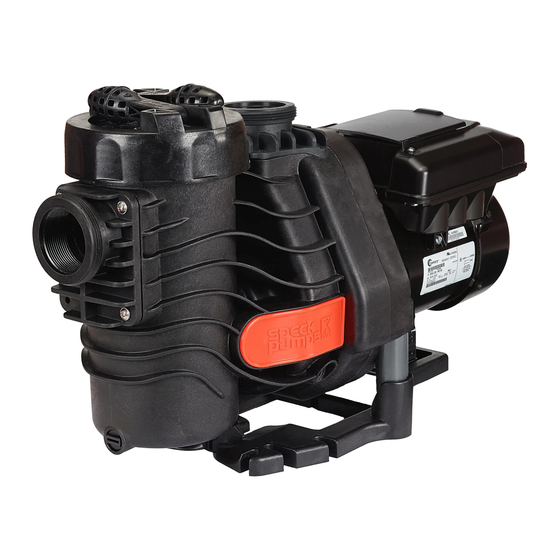
- Page 1 Installation, Operating, and Service Manual EasyFit ® 1.65 THP Swimming Pool Pump...
- Page 2 904-739-2626 Fax: 904-737-5261 Website: www.usa.speck-pumps.com Email: technical.usa@speck-pumps.com Date of Installation: Installed by: Serial Number: For Service Call: Manufactured by Speck Pumps, Jacksonville Florida USA, ©All Rights Reserved. This document is subject to change without notice. SAVE THESE INSTRUCTIONS! Rev 02/2015...
-
Page 3: Important Safety Instructions
OWNER’S MANUAL Swimming Pool Pump READ THIS MANUAL CAREFULLY BEFORE USING THE SPECK PUMP Important Notice: This manual contains important information about the installation, operation and safe use of this product. This information should be given to the owner and/or operator of this equipment. WARNING: This product must be installed and serviced by a qualified pool professional, and must conform to all national, state, and local codes. -
Page 4: Motor Manual
SECTION 1 EQUIPMENT OPERATION AND MAINTENANCE 4. Install the 70 x 6mm o-ring (part# 919) on the back of 1/1 LOCATION the discharge fitting. Secure the discharge fitting to the top of the pump casing (part# 101) using four (4) 6 x 22mm 1. - Page 5 SECTION 1 EQUIPMENT OPERATION AND MAINTENANCE Option # Suction Fitting Discharge Fitting Replaces Pump Model(s) W78.50.006 1.5” or 2” NPT Pentair Ultra-Flow ® ® W78.50.007 1.5” or 2” NPT Pentair WhisperFlo & IntelliFlo ® ® ® W78.50.005 1.5” or 2” NPT Hayward Super Pump &...
- Page 6 SECTION 2 TROUBLESHOOTING GUIDE PROBLEM POSSIBLE CAUSES SOLUTION 1. Pump will not prime. a. Suction air leak. Make sure the see-through lid and o-ring are clean and properly positioned. Tighten see-through lid (hand tight). Tighten all pipes and fittings on suction side of the pump.
- Page 7 2. To the fullest extent permitted by law, the Limited Warranty will be void and of no force or effect and Speck Pumps - Pool Products, Inc.
-
Page 8: Jacksonville, Fl
Buyer’s operation and maintenance of the pump and motor in strict accordance with Speck Pumps - Pool Products, Inc.’s printed operator/maintenance manuals delivered with the pump and motor. - Page 9 SECTION 5 REPLACEMENT PARTS & EXPLODED VIEW 160.2 160.1 156.1 412.1 156.2 156.3 Alternate Discharge Fittings 412.5 174.2 412.2 161.2 412.4 914.2 554.2 Alternate Suction Fittings 182.1 153.6 153.4 153.3 153.2 153.1 182.2 2999999319 - Rev. 0215 - EasyFit...
- Page 10 SECTION 5 REPLACEMENT PARTS & EXPLODED VIEW - continued PART DRAWING DESCRIPTION NUMBER NUMBER REQUIRED 2921116022 160.2 LOCK RING WITH HANDLES - LID 2901410122 CASING 2901413002 NAME PLATE - ORANGE 2901411304 FLANGE 2901489400 BASE 2901416102 161.2 SEAL HOUSING (-I, -II, -IV, -V, -VI) 2901416103 161.2 SEAL HOUSING (1.65, -III)
- Page 11 2999999319 - Rev. 0215 - EasyFit...
- Page 12 VARIABLE SPEED USER MANUAL Premium Efficiency Variable Speed Motor...
- Page 13 COPYRIGHT Copyright 2013, Regal Beloit America, Inc. Tipp City, Ohio. All rights reserved. TRADEMARKS All trademarks and registered trademarks® are the property of their respective companies. The information in this document incorporates proprietary rights and is not to be duplicated wholly or in part without the express written permission of Regal Beloit Corporation and / or Regal Beloit America, Inc.
-
Page 14: Table Of Contents
Table of Contents Safety ..................... 2 1. Introduction ................... 3 2. Navigation Overview ..............3 3. Quick Start Instruction ..............5 3.1 Quick Start Guide (Using Factory Default Schedule) ......5 3.2 Quick Start Guide (User Defined Custom Schedule) ......6 4. Overview ..................8 5. Wiring .................... 9 6. User Interface Operation ............12 6.1 LED and Function Overview ............. -
Page 15: Safety
SAFETY Safety is emphasized throughout this user manual. These are safety alert symbols and signal words. They alert the user to potential per- sonal injury hazards. Obey all safety messages to avoid possible injury or death or damage to equipment and other property. DANGER DANGER DANGER indicates a hazardous situation which, if not avoided, will... -
Page 16: Introduction
Introduction The V-Green 165 is a premium efficiency variable speed motor that ® provides tremendous program flexibility in terms of motor speed and time settings. The variable speed V-Green 165 is intended to enable running at the lowest speeds needed to maintain a sanitary environment, which in turn minimizes energy consumption. - Page 17 If power is connected to the V-Green 165 motor, pressing any of the following buttons referred to in section 2 could result in the motor starting. Failure to recognize this could result in personal injury or damage to equipment. Note: The START button must be pressed for the V-Green 165 to operate.
-
Page 18: Quick Start Instruction
• Ability to configure freeze protection temperature. • Ability to view actual speed and power of the V-Green 165 in real time. • Ability to adjust the V-Green 165 motor speed in 25 RPM increments (to fine tune flow for certain pool installations). •... -
Page 19: Quick Start Guide (User Defined Custom Schedule)
Quick Start Guide (User-defined custom schedule) A V-Green 165 user can set the program DURATION and SPEED for STEP 1, STEP 2, STEP 3 & OVERRIDE keys. NOTE: V-Green 165 must be Stopped (Press STOP Key) for program- ming DURATION and SPEED of the STEP 1, STEP 2, and STEP 3 keys. - Page 20 5. Press STEP 2, STEP 3, or OVERRIDE key. Repeat steps 1- 4 to program the corresponding DURATION and SPEED for each button. 6. Press START to run the V-Green 165 based on the pro- grammed 24 hour schedule. 7. Pressing the STOP button will stop the V-Green 165. NOTE: The V-Green 165 can only be set to operate on a 24-hour schedule.
-
Page 21: Overview
Overview NOTICE The V-Green 165 can and should be optimized to suit individual pool conditions. Specific conditions including pool size, other devices, features, and environmental factors can all impact the optimal settings. Program customization may require some trial-and-error to determine the most satisfactory settings as dictated by the conditions. -
Page 22: Wiring
Wiring The V-Green 165 controller must be wired according to the locally adopted version of the NEC. A licensed, qualified electrician should complete the wiring for this product. Failure to comply with this may result in death, serious personal injury or property damage. The V-Green 165 controller must be wired according to the locally adopted version of the NEC. - Page 23 Power should be turned off when installing, servicing, or repairing electrical components. Observe all warning notices posted on the existing equipment, V-Green 165, and in these installation instructions. EARTH (RED OR WHITE) (BLACK) EARTH 208-230V POWER SOURCE Figure 3: Mains Connection Diagram...
- Page 24 V-Green 165 Controller UI DIGITAL INPUT CONNECTOR Automation System or J202 Solar System Controller STEP 1 (pin 1) STEP 2 (pin 2) STEP 3 EXTERNAL SUPPLY (pin 3) Vac or OVER RIDE (pin 4) COMMON (pin 5) External Supply Range: 18-30V AC (24V AC+/- 20%) 9-30V DC (12/24V DC +/- 20%) Figure 4: Wiring Diagram for Digital Inputs...
-
Page 25: User Interface Operation
User Interface Operation LED and Function Overview V-Green 165 UI LED Indication and respective functionalities V-Green 165 UI LED Indication and respective functionalities Key f or L EDs Key f or L EDs Solid O N I ndication Solid ... -
Page 26: User Interface Key Pad Overview
User Interface Key Pad Overview If power is connected to the V-Green 165 motor, pressing any of the following buttons referred to in this section 6.2 could result in the motor starting. Failure to recognize this could result in personal injury or damage to equipment. 1. - Page 27 Button Duration Speed (In Hours) (In RPM) STEP 1 3100 STEP 2 2600 STEP 3 1600 OVERRIDE 3450 Table 3: Factory default schedule Schedule Tables Use the tables below to record a personalized operating schedule. Recording the planned schedule in the table below will make the pro- gramming process easier and will help the user remember the custom settings in case of inadvertent loss of schedule.
-
Page 28: Running V-Green 165 From Keypad
Setup #2 Step 1 Step 2 Step 3 Duration Speed Table 4: Custom Schedule Running V-Green 165 from Keypad If power is connected to the V-Green 165 motor, pressing any of the following buttons referred to in this section 6.4 could result in the motor starting. Failure to recognize this could result in personal injury or damage to equipment. - Page 29 4. This sequence will then repeat for STEP 2 and then STEP 3 with- out the V-Green 165 stopping. 5. At the end of STEP 3, the V-Green 165 will wait if necessary for the completion of the 24-hour schedule. During this waiting period (if applicable), all of the “active step LEDs”...
-
Page 30: Override
OVERRIDE The V-Green 165 is equipped with an OVERRIDE feature, which can be engaged to temporarily run at higher or lower speeds ranging between 600 to 3450 RPM. Once the OVERRIDE duration has elapsed, the V- Green 165 will automatically return to the programmed schedule. 1. -
Page 31: Schedule Advance
NOTE: Pressing/Holding OVERRIDE key for more than three (3) seconds will cancel OVERRIDE mode. NOTE: During the OVERRIDE mode, the V-Green 165 will not start with the priming sequence. NOTE: It is recommended that you do not set the OVERRIDE duration to 0 HRS. - Page 32 2. Press the UP (+) or DOWN (-) arrows to set the desired delay time after which the 24-hour schedule should start. The Schedule Advance mode will automatically start after the desired delay time is selected. The Schedule Advance mode can be canceled by press- ing the STOP key.
-
Page 33: Key Lockout
Key Lockout Key lockout will not prevent the motor from being stopped by pressing the STOP button. If the motor is operating in “key lockout” mode, and being controlled through a digital or serial input, the motor will only temporarily stop (4 min.) it will then restart. The V-Green 165 user interface has a “key lockout”... -
Page 34: Motor Pause
Motor Pause The V-Green 165 user interface has a “motor pause” feature that will allow the user to temporarily stop the V-Green 165 for maintenance work without disrupting the 24 hour schedule (i.e., for backwashing the filter). If the V-Green 165 is currently running, the user can press and hold the START button for more than three (3) seconds and the V-Green 165 will stop and remain off until the user presses and holds the START button again for more than three (3) seconds. -
Page 35: 6.10 Reset Factory Defaults
6.10 Reset Factory Defaults The V-Green 165 user interface has a “Reset to Factory Defaults” feature to restore the schedule settings back to the original values programmed at the factory. The user must press and hold the STOP and OVERRIDE buttons for three (3) seconds to reset the settings back to factory defaults. -
Page 36: Control With Digital Inputs
Control with Digital Inputs The user can run the V-Green 165 at the programmed STEP 1, STEP 2, STEP 3, or OVERRIDE speeds by utilizing the four digital inputs. STEP 1, STEP 2, STEP 3, or OVERRIDE are equivalent to Digital Input 1, 2, 3 or 4 respectively. -
Page 37: Dip Switches
NOTE: If no digital input is detected, the V-Green 165 will automatically start the 24 hour schedule if the START key was pressed prior to the application of a digital input. Access to these terminals is in close proximity to the mains connectors which carry line voltage capable of causing personal injury or damaging the equipment if contact is made. -
Page 38: Care And Maintenance
Care and Maintenance The V-Green 165 is both reliable and robust in harsh environments. However, this product does contain electronics that are cooled by a fan mounted to the V-Green 165. In order to ensure optimum reliability of this product, it is recommended to clean the fan inlet on the back of the V-Green 165 once a month. - Page 39 Below is the behavior of the FAULT LED when a FAULT is detected: When a FAULT is present, and the motor is not running, only the FAULT LED and power LED will illuminate. When a FAULT is present, and the motor is running, then the FAULT LED will illuminate.
-
Page 40: Specifications
Specifications Overall Ratings Input Voltage 208 - 230 Vrms nominal Input Current 10.5 - 10.0 Arms Input Frequency Single phase, 60 Hz Control Terminals 18-30V AC (24V AC+/- 20%) or 9-30V DC (12/24V DC +/- 20%) Auxiliary Load Terminals Maximum Continuous Load 1.65 THP (Total Horse Power) Speed Range 600 - 3450 RPM... -
Page 41: Troubleshooting Guide
Troubleshooting Guide Diagnosing certain symptoms may require close interaction with, or in close proximity to, components that are energized with electricity. Contact with electricity can cause death, personal injury, or property damage. When trouble shooting the V-Green 165, diagnostics involving electricity should be cared for by a licensed professional. Symptom Possible Causes Potential Solutions... - Page 42 Disclaimer The information in this document incorporates proprietary rights and is not to be duplicated wholly or in part without the express written permission of Regal Beloit America, Inc. © Copyright 2013. The text and images in this document are not to be modified without express written permission of Regal Beloit Corporation and / or Regal Beloit America, Inc.
- Page 43 Distribution Marketing 1325 Heil Quaker Blvd. LaVergne, TN 37086 Phone: (866) 887-5216 A Regal Brand Fax: (800) 468-2062 www.pool-motors.com © 2013 Regal-Beloit Corporation 2516831-002 10/13...
Need help?
Do you have a question about the EasyFit 1.65 THP and is the answer not in the manual?
Questions and answers