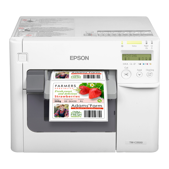
Epson TM-C3500 Series Technical Reference Manual
Hide thumbs
Also See for TM-C3500 Series:
- User manual ,
- Technical reference manual (240 pages) ,
- Developer's manual (101 pages)
Table of Contents
Advertisement
Quick Links
Technical Reference Guide
Series
Product Overview
Describes features and general specifications for the product.
Setup
Describes setup and installation of the product and peripherals.
Handling
Describes how to handle the product.
Application Development Information
Describes how to control the printer and necessary information
when you develop applications.
Maintenance
Describes the efficient management method of multiple printers
and client computers, targeted at the administrators.
M00066602
Rev.C
Advertisement
Table of Contents

Related Manuals for Epson TM-C3500 Series


Summary of Contents for Epson TM-C3500 Series
- Page 1 Series Technical Reference Guide Product Overview Describes features and general specifications for the product. Setup Describes setup and installation of the product and peripherals. Handling Describes how to handle the product. Application Development Information Describes how to control the printer and necessary information when you develop applications.
- Page 2 • Neither is any liability assumed for damages resulting from the use of the information contained herein. • Neither Seiko Epson Corporation nor its affiliates shall be liable to the purchaser of this product or third parties for damages, losses, costs, or expenses incurred by the purchaser or third parties as a result of: accident, misuse, or abuse of this product or unauthorized modifications, repairs, or alterations to this product, or (excluding the U.S.) failure to strictly comply with Seiko Epson Corporation’s operating...
-
Page 3: For Safety
For Safety Key to Symbols The symbols in this manual are identified by their level of importance, as defined below. Read the following carefully before handling the product. You must follow warnings carefully to avoid serious bodily injury. WARNING Provides information that must be observed to prevent damage to the equipment or loss of data. -
Page 4: Warnings
If water or other liquid spills into this equipment, unplug the power cord immediately, and then contact your dealer or a Seiko Epson service center for advice. Continued usage may lead to fire. Do not use aerosol sprayers containing flammable gas inside or around this... -
Page 5: Cautions
Cautions Do not connect cables in ways other than those mentioned in this manual. Different connections may cause equipment damage and burning. Be sure to set this equipment on a firm, stable, horizontal surface. The product may CAUTION break or cause injury if it falls. -
Page 6: About This Manual
About this Manual Aim of the Manual This manual was created to provide information on development, design, and installation of systems and development and design of printer applications for developers. Manual Content The manual is made up of the following sections: Chapter 1 Product Overview Chapter 2... -
Page 7: Table Of Contents
Contents ■ For Safety ..........................3 Key to Symbols ............................3 Warnings ..............................4 Cautions ..............................5 ■ Restriction of Use ........................5 ■ About this Manual ........................ 6 Aim of the Manual ..........................6 Manual Content .............................6 ■ Contents..........................7 Product Overview ................ 11 ■... - Page 8 Function of the DIP Switches ......................85 ■ Setting the Printer Driver ....................86 Banding Reduction..........................86 TM-C3500 PrinterSetting........................88 Setting EPSON Status Monitor 3 ......................89 Handling ..................97 ■ Replacing the Ink Cartridge ..................... 97 ■ Replacing Maintenance Box ..................100 ■...
- Page 9 Factory settings...........................163 How to initialize the settings to the factory settings................163 ■ Troubleshooting ........................ 164 Error Recovery Method ........................164 HELP for EPSON Printers ........................167 ■ Setting Check Modes ...................... 169 Self-test Mode .............................169 Status Sheet Printing (Ethernet interface model only) ..............172 ■...
- Page 10 ■ System Configuration .......................199 Installing the Printer..........................199 Distributing the Printer Driver ......................200 ■ Maintenance ........................201 Changing the Printer Settings......................201 Changing the Printer Driver Settings....................206 Monitoring the Network Printer ......................207 Replacing the Printer......................... 208 ■ For Inquiries ........................210...
-
Page 11: Product Overview
Product Overview This chapter describes features and specifications of the product. Features The TM-C3500 series (TM-C3500/ TM-C3510/ TM-C3520) are a 4-color ink jet printer that offers high speed easy operability and high reliability required for on-demand label printing. Printing • High-speed printing ... -
Page 12: Model
(SDK is provided as API to make original application for obtained printer status.) • Dedicated sample program is prepared. (program language: VB.NET, C + +, C#) • EPDI (EPSON Printer Driver Interface) for TM-C3500 allows the printer driver setting also from the application. Others •... -
Page 13: Parts Name And Function
Chapter 1 Product Overview Parts Name and Function Front Control panel Power switch cover Power switch Release lever Paper ejection guide Paper ejection table Ink cartridge cover Paper ejection Paper ejection tray Roll paper cover guide lock Control panel Power LED Paper LED Status LED Ink LED... - Page 14 Back Fanfold paper cover Paper feed guide Fanfold paper guide Connector (lower rear) Status sheet button Ethernet Connector USB connector DC power connector Cable hook Link LED...
-
Page 15: Power Switch
Chapter 1 Product Overview Power Switch Before turning on the printer, be sure to check that the AC adapter is connected to the power supply. CAUTION ❏ When DIP switch 1 is OFF: • Turns the power on after the POWER button has been pressed while the power is OFF. •... -
Page 16: Cut Button
CUT button ❏ If "Media position detection settings" is set to "Full-page label/Continuous paper/ Transparent full-page label", feeds the paper to the autocutting position for the top of the next page, and performs autocutting. ❏ If "Media position detection settings" is set to "Die-cut label (BM)", "Black mark continuous paper", or "Die-cut label (Gap)/Transparent die-cut label", feeds the paper to the autocutting position according to the black mark or the gap between labels, and performing autocutting. -
Page 17: Lcd Contrast Adjustment Button
Chapter 1 Product Overview LCD contrast adjustment button Adjusts the LCD contrast. The LCD contrast adjustment button is located under the ink cartridge cover. The adjusted value is saved in the non-volatile memory. Even after the power is turned on again, the adjusted value saved last time is applied. -
Page 18: Status/Error Indications
For error recovery methods, see "Troubleshooting" on page 164 or the help for the driver. (For details on how to display HELP for EPSON Printers, see the help for the driver on page 144.) : Lit up : Blinking... - Page 19 Chapter 1 Product Overview : Lit up : Blinking : Off : No change ## : Error code — Printer Status Status Power Paper M/B COVER OPEN Maintenance box cover open (*) — — NO MAINT BOX No maintenance box (*) —...
-
Page 20: Ink Cartridge And Maintenance Box Status
Ink Cartridge and Maintenance Box Status You can check the status of the printer, the ink cartridges of each color, and the maintenance box from the LCD. Row 1 displays the printer's status Row 2 displays the status of the ink cartridges and maintenance box. -
Page 21: Beeper
Chapter 1 Product Overview Beeper When an error occurs while “Beep Notification Setting at an Error” is enabled, the beeper performs “Sound the beeper on an error” shown in the below table. The beeper continues to beep until all the causes of error are removed. When “Completion Beeper Setting”... -
Page 22: Auto Nozzle Check System
Auto nozzle check system This product has an “Auto nozzle check system” that detects missing dots. You can select the “Nozzle check mode” depending on level of requirement for missing dots. The following table shows the timing for auto nozzle check for each nozzle check mode (printing operation mode). - Page 23 Chapter 1 Product Overview The following table shows the conditions for permitted missing dots and auto cleaning for each nozzle check mode. Anti-missing No Missing Anti-missing Anti-missing Condition Read Mode Dot Detection Dot Mode Color Mode (Default) Mode No 2 consecutive 1 missing dot or missing dots and Permitted missing dots...
- Page 24 This "Auto nozzle check" system cannot detect 100% of dot missing cases. In cases extremely high reliability and safety is required, Epson recommends the use of font constructed of 3 vertical dots or more in "Anti-missing Dot Mode" or "Anti-missing Read Mode"...
-
Page 25: Software
This software is used in configuration of the printer environment for multiple clients. EPSON Printer Deployment The user can set the initial settings for multiple EPSON Deployment Tool printers at a time. - Page 26 Purpose Utilities Specifications Service installed as a resident program on the computer When the TM-C3500 is replaced for service or other reason, this detects the printer connection and automatically changes the output printer of the printer driver. This allows the printer to be replaced without Maintenance USB Replacement Service changing settings in the application.
-
Page 27: Product Specifications
Chapter 1 Product Overview Product Specifications Printing method Serial ink jet, dot matrix 4 color (KCMY) printing Paper feed Forward and reverse friction feed Autocutter Cutting method By separated-blade scissors Auto-cut type Full cut (cuts paper completely) Graphic resolution 360 dpi × 360 dpi, 720 dpi × 360 dpi Print speed 103 mm/s (printing width 56 mm, 360 dpi ×... - Page 28 Temperatures/ Printing 10 to 35C, 20 to 80%RH (no condensation) humidity Storage When packed (ink not loaded): -20 to 60C, 5 to 85%RH (no (See condensation) "Environmental -20C or 60C: up to 120 hours Conditions" on Ink loaded: -20 to 40C page 63 -20C: up to 120 hours details.)
-
Page 29: Hardware Requirements
Chapter 1 Product Overview Hardware Requirements Microsoft Windows 8 (32 bit/ 64 bit) Microsoft Windows 7 SP1 (32 bit/ 64 bit) Microsoft Windows Vista SP2 (32 bit/ 64 bit) Microsoft Windows XP SP3 (32 bit) Microsoft Windows XP SP2 (64 bit) Microsoft Windows Server 2012 Microsoft Windows Server 2008 R2 SP1 Microsoft Windows Server 2008 SP2 (32 bit/ 64 bit) -
Page 30: Paper Specifications
Paper Specifications The following is the type and the size of paper specified for this printer. When using paper other than the specified, users must evaluate the recognition rate in advance to avoid deterioration of the paper feed accuracy/barcode recognition rate/print quality and frequent occurrence of paper jams. -
Page 31: Continuous Paper
Chapter 1 Product Overview Paper type Category Form Width Wristband Wristband Roll paper 30 mm {1.18"} (Paper width) Continuous paper This is continuous paper. Media type Plain / Matte Media source Roll paper Paper width 30 to 108 mm {1.18 to 4.25"} Paper thickness 0.084 to 0.124 mm {0.003 to 0.004"} Paper core... - Page 32 Black mark continuous paper <Back side> <Printing side> Center of black marks Center of paper Paper feeding width Center of paper width direction Perforation position 0.5 mm or more (When using fanfold paper) Black mark receipt Black mark width Media type Plain / Matte Media source Roll paper...
- Page 33 Chapter 1 Product Overview Media type Plain / Matte Media source Fanfold paper Paper width 50 to 108 mm {1.97 to 4.25"} Black mark width 13 mm {0.51"} or more Black mark length 5 mm {0.19"} or more 8.5 mm 1 mm {0.33 0.039"} Center of a black mark Gaps between black marks 15 to 304.8 mm {0.59 to 12.0"}...
- Page 34 Full-page label Backing paper width Backing paper Label area Label width Edge cutoff Edge cutoff Media type Plain label / Matte label / Synthetic label / Glossy label Media source Roll paper Backing paper width 30 mm to 112 mm {1.18 to 4.41"} Label width 25.4 to 108 mm {1 to 4.25"} 2 mm ...
- Page 35 Chapter 1 Product Overview Die-cut label(Gap) Backing paper width Edge R Backing paper Label area Edge cutoff Label width Edge cutoff Media type Plain label / Matte label / Synthetic label / Glossy label Media source Roll paper Backing paper width 30 to 112 mm {1.18 to 4.41"} Label width 25.4 to 108 mm {1 to 4.25"}...
- Page 36 Form of perforated line Plain media : 1 mm {0.039"} uncut, 5 mm {0.2"} cut Fine media : 1 mm {0.039"} uncut, 5 mm {0.2"} cut PET film : 0.6 mm uncut, 8.4 mm cut Do not use the paper with a hole or cutout. ...
- Page 37 Chapter 1 Product Overview Die-cut label (BM) When removing all the fringes Paper width Edge R Backing paper Label area Label width Edge cutoff Edge cutoff <Back side> <Printing side> Center of paper Center of black marks width Paper feeding Center of paper width direction Perforation position...
- Page 38 Label width 25.4 to 108 mm {1 to 4.25"} Label length 15 to 1,117.6 mm {0.59 to 44"} Gap between labels 3 to 6 mm {0.12 to 0.24"} 2 mm 0.5 mm {0.079 0.02"} Left and right outer edges Label edge R 1.5 mm {0.059"} or less Width of a black mark...
- Page 39 Chapter 1 Product Overview Media type Plain label / Matte label Media source Fanfold paper Backing paper width 50 to 112 mm {1.97 to 4.41"} Label width 46 to 108 mm {1.81 to 4.25"} Label length 15 to 301.8 mm {0.59 to 11.88"} Gap between labels 3 to 6 mm {0.12 to 0.24"} 2 mm ...
- Page 40 Wristband <Back side> <Printing side> Center of black marks Center of paper width Center of paper width Paper feeding direction Black mark paper Black mark width Media type WB-S/M/L series (Synthetic media) Media source Roll paper Paper width WB-S/M/L series: 36 mm {1.42"} Black mark width 13 mm {0.51"} or wider Black mark length...
-
Page 41: Print Area And Cutting Position
Chapter 1 Product Overview Print Area and Cutting Position Continuous paper / Roll paper When “Extend Printable Area” is disabled Top, bottom, left, right margins: 1.5 mm (Typical value) Paper width Paper feeding direction Center of paper width Auto-cut position Auto-cut position 1.5 mm 1.5 mm... - Page 42 When "Extend Printable Area" is enabled Top, bottom, left, right margins: 0 mm (Typical value) Paper width Paper feeding direction Center of paper width Auto-cut position Auto-cut position Print area Paper width Paper If you enabled "Extend Printable Area", printing is done with settings for no margins, but the printing might protrude beyond the paper/label, depending on the actual print posi- tion and the set position for the paper/label.
- Page 43 Chapter 1 Product Overview Black mark continuous paper / Roll paper When "Extend Printable Area" is disabled Top, bottom, left, right margins: 1.5 mm (Typical value) Paper width Paper feeding direction Center of paper width Auto-cut position Auto-cut position Print area 1.5 mm 1.5 mm Print area width...
- Page 44 When "Extend Printable Area" is enabled Top, bottom, left, right margins: 0 mm (Typical value) Print area width Paper feeding direction Center of paper width Auto-cut position Auto-cut position Print area Print area width Paper Black mark position If you enabled "Extend Printable Area", printing is done with settings for no margins, but the printing might protrude beyond the paper/label, depending on the actual print posi- tion and the set position for the paper/label.
- Page 45 Chapter 1 Product Overview Black mark continuous paper/ Fanfold paper When "Extend Printable Area" is disabled Top, bottom, left, right margins: 1.5 mm (Typical value) Paper width Center of paper width Paper feeding direction Perforated line Auto-cut position Auto-cut position Perforated line Auto-cut position Print area...
- Page 46 When "Extend Printable Area" is enabled Top, bottom, left, right margins: 0 mm (Typical value) Paper width Center of paper width Paper feeding direction Perforated line Auto-cut position Auto-cut position Perforated line Auto-cut position Print area Print area width Black mark position ...
- Page 47 Chapter 1 Product Overview Full-page label / Roll paper When "Extend Printable Area" is disabled Top, bottom, left, right margins: 1.5 mm (Typical value) Paper width Paper feeding direction Center of paper width Auto-cut position Auto-cut position 1.5 mm 1.5 mm Print area width Print area 2.0 mm...
- Page 48 When "Extend Printable Area" is enabled Top, bottom, left, right margins: 0 mm (Typical value) Paper width Paper feeding direction Center of paper width Auto-cut position Auto-cut position Outer edge (Removed) Outer edge (Removed) Print area width 2.0 mm 2.0 mm Print area Label area Backing paper...
- Page 49 Chapter 1 Product Overview Die-cut label(Gap) / Roll paper When "Extend Printable Area" is disabled Top, bottom, left, right margins: 1.5 mm (Typical value) Paper width Paper feeding direction Center of paper width Perforated line Auto-cut position Auto-cut position 1.5 mm 1.5 mm Print area width Outer edge (Removed)
- Page 50 When "Extend Printable Area" is enabled Top, bottom, left, right margins: 0 mm (Typical value) Paper width Center of paper width Paper feeding direction Perforated line Auto-cut position Auto-cut position Paper width Outer edge (Removed) Outer edge (Removed) 2.0 mm 2.0 mm Print area Label area...
- Page 51 Chapter 1 Product Overview Die-cut label(BM) / Roll paper When "Extend Printable Area" is disabled Top, bottom, left, right margins: 1.5 mm (Typical value) Paper width Paper feeding direction Center of paper width Perforated line Auto-cut position Auto-cut position Auto-cut position Print area Label area Print area width...
- Page 52 When "Extend Printable Area" is enabled Top, bottom, left, right margins: 0 mm (Typical value) Paper width Paper feeding Center of paper width direction Perforated line Auto-cut position Auto-cut position Auto-cut position Print area Label area Print area width Backing paper Edge cutoff 2.0 mm Edge cutoff 2.0 mm Black mark...
- Page 53 Chapter 1 Product Overview Die-cut label(BM) / Fanfold paper When "Extend Printable Area" is disabled Top, bottom, left, right margins: 1.5 mm (Typical value) Paper width Paper feeding Center of paper width direction Perforated line Auto-cut position Auto-cut position Perforated line Auto-cut position Print area Print area width...
- Page 54 When "Extend Printable Area" is enabled Top, bottom, left, right margins: 0 mm (Typical value) Paper width Paper feeding Center of paper width direction Perforated line Auto-cut position Auto-cut position Perforated line Auto-cut position Print area Label area Print area width Backing paper Edge cutoff 2.0 mm Edge cutoff 2.0 mm...
- Page 55 Chapter 1 Product Overview Wristband/roll paper (WB-S series) When “Extend Printable Area“ is disabled Top, bottom, left. right margins: 1.5 mm (Typical value) Paper width Paper feeding direction 36 mm Center of paper width Black mark position (back) 5.5 mm Autocutting position Recommended print area for text and barcodes (*dimension)
- Page 56 When “Extend Printable Area“ is enabled Top, bottom, left. right margins: 0 mm (Typical value) Paper width Paper feeding direction 36 mm Center of paper width 5.5 mm Autocutting position Recommended print area for text and barcodes (*dimension) 11.0 mm 15.0 mm Autocutting position Print area...
- Page 57 Chapter 1 Product Overview Wristband/roll paper (WB-M series) When “Extend Printable Area“ is disabled Top, bottom, left. right margins: 1.5 mm (Typical value) Paper width 36 mm Center of paper width Paper feeding direction 5.5 mm Autocutting position Recommended print area for text 11.0 mm and barcodes (*dimension) 15.0 mm...
- Page 58 When “Extend Printable Area“ is enabled Top, bottom, left. right margins: 0 mm (Typical value) Paper width 36 mm Center of paper width Paper feeding direction 5.5 mm Autocutting position Recommended print area for text and barcodes (*dimension) 11.0 mm 15.0 mm Autocutting position Print area...
- Page 59 Chapter 1 Product Overview Wristband/roll paper (WB-L series) When “Extend Printable Area“ is disabled Top, bottom, left. right margins: 1.5 mm (Typical value) Paper width 36 mm Paper feeding direction Center of paper width 5.5 mm Autocutting position 15.0 mm Recommended print area for text and barcodes (*dimension) 28.0 mm...
- Page 60 When “Extend Printable Area“ is enabled Top, bottom, left. right margins: 0 mm (Typical value) Paper width 36 mm Paper feeding direction Center of paper width 5.5 mm Autocutting position 15.0 mm Recommended print area for text and barcodes (*dimension) 28.0 mm 24.0 mm Autocutting position...
-
Page 61: Paper Ejection Tray
Chapter 1 Product Overview Paper Ejection Tray See the "Attaching the Paper Ejection Tray" on page Black Mark Paper type Plain Media, Fine Media, PET Film Receipt Paper form Fanfold paper Paper size Width 76 to 105 mm × length 54 to 148 mm Paper 0.119 to 0.151 mm thickness... -
Page 62: Maintenance Box
Maintenance Box Model number SJMB3500 Type Maintenance box with a built-in waste ink absorber Life None Temperatures Conforms to "Environmental Conditions" on page Electrical Characteristics Power supply Dedicated AC adapter Input voltage (rated) 100 V to 240 V Frequency (rated) 50 Hz to 60 Hz Power Operating... -
Page 63: Environmental Conditions
Not operating 850 to 1060 hPa (approximately 0 to 1500 m above sea level) (including in transportation) Acoustic noise During Approximately56 dB (ANSI Bystander position) operation (Based on Epson evaluation conditions including the use of the (including using autocutter) the autocutter) -
Page 64: External Dimensions
External Dimensions • Height: 261 mm • Width: 310 mm • Depth: 283 mm 465 (When the paper ejection tray is expanded) 396 (When the paper ejection tray is closed) [Unit: mm]... -
Page 65: Restrictions
Chapter 1 Product Overview Restrictions ❏ If you turn the power off the product using the power button, the print head is automatically capped, which prevents the ink from drying. After installing the ink cartridges, be sure to turn the power off using the power button when you are not using the product. Do not pull out the power plug or trip the breaker while the power is on. -
Page 67: Setup
Chapter 2 Setup Setup This chapter describes setup and installation of the product and peripherals. Work Flow This chapter consists of the following sections along with the setup flow of the product and peripherals. 1.Checking the Items Included in the Package (page 68) 2.Installing the Printer (page 69) 3.Attaching the Power Switch Cover (page 70) 4.Setting Up the Printer (page 72) -
Page 68: Checking The Items Included In The Package
Checking the Items Included in the Package When using the printer for the first time, check the items included in the package. The items included in the package are as follows: User’ s Manual TM-C3500 Series Dedicated AC adapter AC cable *1 Ink cartridge... -
Page 69: Installing The Printer
Chapter 2 Setup Installing the Printer Install the printer in an appropriate location with sufficient space around it. Important Notes on Installation • The printer must be installed horizontally. • Leave enough space in front of the printer for the ink cartridge cover and the roll paper cover to be fully opened. -
Page 70: Attaching The Power Switch Cover
Attaching the Power Switch Cover Attaching the power switch cover prevents accidental pressing of the power switch. Before attaching the power switch cover, set DIP switch 1 to ON. (For details, see “Setting the DIP switches”Setting the DIP Switches on page 84.) The printer power can then be switched by turning the AC supply on and off, and you can also control the printer power with a device such as a distribution board In this case, the power switch is used to reset the... - Page 71 Chapter 2 Setup To switch the power switch by inserting a long, thin object into a hole Attach the power switch cover after punching the hole in it. The hole cannot be punched in the power switch cover after it is attached to the printer. Punch a hole in the power switch cover by pushing the middle of it with a hard, fine-tipped object.
-
Page 72: Setting Up The Printer
Setting Up the Printer Set up the printer using Install Navi. Install Navi is included in the supplied CD-ROM. Turn on the computer to be connected to the printer. Make sure that the printer is turned off. Be sure to turn the printer off. Set the CD-ROM in the computer, and Launcher automatically starts up.... - Page 73 Chapter 2 Setup Later in the setup procedure, "Media Layout Creation" window appears. When "Media Layout Creation" window appears, if you do not use the roll paper included in the package, you have to create a new media layout. For the procedure to create a new media layout, see Media Layout Creation on page 74....
-
Page 74: Media Layout Creation
Media Layout Creation On "Media Layout Creation" window, select [Yes]. Click [Next]. The following window appears. Select either [Roll Paper] or [Fanfold Paper] and click [Next]. - Page 75 Chapter 2 Setup The following window appears. Select the media to be used and click [Next]. When fanfold paper is selected, only [Die-cut Label (BM)] and [Black Mark Continuous Paper] can be selected. The following window appears. Enter each item and click [Next]. Item Description Media Layout Name...
- Page 76 Item Description Enter the width and length of the media to be used. Media Layout The information to be entered is different depending on the media type selected in Step 3. The following window appears. Enter each item and click [Next]. Item Description Media Type...
- Page 77 Chapter 2 Setup "Restarting the Printer” screen appears. Restart the printer to apply the new settings.
-
Page 78: Ejection Angle Of Printed Paper
Ejection Angle of Printed Paper Make sure paper is ejected straight from the paper ejection guides, as shown in the illustration. If paper is not ejected straight due to such causes as an obstruction, the print result may be distorted. -
Page 79: How To Display The Printer Driver
Click [Settings] on [Start] menu, and click [Control Panel]. For Windows Server 2003 R2: Click [Printers and Faxes] on [Start] menu. Right-click [EPSON TM-C3500], and click [Printing References]. The printer driver screen is displayed. The barcode printing position is moved based on the amount of margin. -
Page 80: Registering The Media Layout
Registering the Media Layout If the paper size to use is not in Media Layout, register the user defined media. The registered layout will be stored in [Favorite Setting] to use from application of users. (For details on how to register the favorite setting, see Favorite Setting on page 120.) Display the printer driver window. - Page 81 Chapter 2 Setup Click [Save]. User Defied Media will be registered and displayed on the list of [Defined Media Layout]. Registered paper...
-
Page 82: Attaching The Paper Ejection Tray
Attaching the Paper Ejection Tray If you attach the paper ejection tray, you can temporarily store the printed paper in the tray. Follow the steps below to install/adjust the ejection tray. Paper may not stay in the paper ejection tray depending on the paper curl and length. ... - Page 83 Chapter 2 Setup Slide the bottom tray to align it with the paper length. Pull up the lever at the bottom-right of the paper ejection tray to lock it.
-
Page 84: Setting The Dip Switches
Setting the DIP Switches Change the DIP switch settings in the following cases. • When attaching the power switch cover to prevent the power switch from being pressed • When changing the LCD display language • When changing the volume of the buzzer Setting Procedure Follow the steps below to change the DIP switch settings. -
Page 85: Function Of The Dip Switches
Chapter 2 Setup Function of the DIP Switches Factory Function settings Operation of the power switch Reset Power ON/OFF Internal use Fixed to OFF (Do not change) Internal use Fixed to OFF (Do not change) LCD display language settings See the table below Buzzer volume High When attaching the power switch cover to prevent the power switch to be pressed, set DIP... -
Page 86: Setting The Printer Driver
In addition to the printing preferences, the printer driver also provides the printer settings and various utility functions. • Banding Reduction • TM-C3500 PrinterSetting • Setting for EPSON Status Monitor 3 Banding Reduction You can reduce banding (extraneous lines in printing) to obtain better print quality. This function, however, lowers the print speed. - Page 87 Chapter 2 Setup "Advanced" screen appears. Check [Banding Reduction], and click [Close]. The screen returns to "General" window. Click [OK].
-
Page 88: Tm-C3500 Printersetting
TM-C3500 PrinterSetting TM-C3500 PrinterSetting is used to change various printer settings. From TM-C3500 PrinterSetting, you can change the following printer settings: Item Description Media source settings Media source settings Media potision detection settings General Nozzle Check Mode Printer Operation Settings ... -
Page 89: Setting Epson Status Monitor 3
Setting EPSON Status Monitor 3 When EPSON Status Monitor 3 is used, the paper type and the ink level are displayed on a pop- up window when printing. In addition, when a fatal error occurs, an error window is displayed. - Page 90 Select [Driver Utilities] tab and click [Driver Preferences] under [Driver Preferences]. The [Driver Preferences] window is displayed. Check the box of [Use EPSON Status Monitor 3] and click [OK]. [EPSON Status Monitor 3] and [Monitoring Preferences] are displayed in [EPSON Status Monitor 3 Settings] on the Driver Utilities window.
- Page 91 The EPSON Status Monitor 3 will not be activated if an error occurs when not printing. • Clicking the icon for [EPSON Status Monitor 3] on the task tray allows you to display [EPSON Status Monitor 3] at any time....
- Page 92 • The following items can be set in [Monitoring preferences]. Selecting error indications: (See Error notification setting for [Not use EPSON Status Monitor 3] on page 93.) Displaying the [EPSON Status Monitor 3] icon on the task bar: (See Displaying the icon on page...
- Page 93 Chapter 2 Setup Error notification setting for [Not use EPSON Status Monitor 3] Follow the steps below to set error notification for [Not use EPSON Status Monitor 3]. Turn the printer on. Display the printer driver window. (See How to Display the Printer Driver on page 79.)
- Page 94 Error notification setting for [Use EPSON Status Monitor 3] Follow the steps below to set error notification for [Use EPSON Status Monitor 3]. Turn the printer ON. Display the printer driver window. (See How to Display the Printer Driver on page 79.)
- Page 95 Chapter 2 Setup Displaying the icon Keeps icon on the task tray so that user can check as needed. The icon is not displayed when default setting. Follow the steps below to display the icon. Turn the printer ON. Display the printer driver window. (See How to Display the Printer Driver on page 79.)
-
Page 97: Handling
Chapter 3 Handling Handling This chapter describes basic handling of the printer. Replacing the Ink Cartridge When the ink ends, the INK LED lights. Follow the steps below to replace the ink cartridge. Turn the power on and make sure that the INK LED lights. Pull down the ink cartridge cover to the front to open it. - Page 98 If there is a used ink cartridge that requires replacement, slowly push the ink cartridge, check that the lock is released, and pull the ink cartridge out towards you. Shake new ink cartridge package 4 or 5 times before opening it and take out the ink cartridge from the package.
- Page 99 Epson products will not be free of charge even if the warranty period is still valid. ❏ Color adjustment of the product is based on the use of genuine Epson ink cartridges. Use of non-genuine ink cartridges may result in reduced print quality. Use of genuine Epson ink cartridges is recommended.
-
Page 100: Replacing Maintenance Box
Replacing Maintenance Box Do not dismantle the Maintenance box. Do not touch the IC chip on the cartridge. Keep out of reach of children, and do not drink. Do not reuse a maintenance box which has removed and detached a long period. ... - Page 101 Chapter 3 Handling Put the maintenance box into the plastic bag for disposal of used main- tenance box. With the label of replacement facing right, slowly insert the new mainte- nance box. Close the maintenance box cover. After replacing the maintenance box, we recommend that you clean the platen. (See the "Cleaning the platen"...
-
Page 102: Replacing Roll Paper With Fanfold Paper
Replacing Roll Paper with Fanfold Paper Follow the steps below to replace the roll paper with fanfold paper. Press down the release lever, and pull it to the front to open the roll paper cover. Remove the used roll paper. Turn the printer ON. - Page 103 Chapter 3 Handling From TM-C3500 PrinterSetting, specify the media source and the media position detection method. Then, click [Apply Settings]. After setting [Media source], set [Media position detection settings]. Item Description Media source Select [Fanfold paper]. Select the media type. ...
- Page 104 The confirmation window appears. Click [Yes] to send the settings to the printer. The following window appears. Click [OK]. The completion window appears. Click [OK]. On the printer driver window, select [General] tab. Specify the media settings and click [OK].
- Page 105 Chapter 3 Handling Item Description Media Type Select the media type. Print Settings Print Quality Select the print quality. Select the media layout. If the media layout to be used is not included in Media Source/Saving Settings Media Layout the list, create a new layout. See the "Registering the Media Layout"...
- Page 106 Press down the release lever, and pull it to the front to open the roll paper cover. Insert the paper feed guide for fanfold paper into the groove inside the roll paper cover to install it.
- Page 107 Chapter 3 Handling Refer to the shutter adjustment method label on the top of the printer, and open or close the shutters on the platen to match the width of the roll paper. If the shutter is set incorrectly, paper may be jammed or get dirty.
- Page 108 Release the lock of the paper ejection guide with a fine-tipped tool. Slide the paper ejection guide to the very left end, and lock it. Open the cover at the back of the printer, and unlock the fanfold paper guide.
- Page 109 Chapter 3 Handling Adjust the fanfold paper guide to the fanfold paper width. Lock the fanfold paper guide. Turn the printer ON.
- Page 110 Insert the fanfold paper into the paper slot, facing the print surface upward. Insert the paper until it is pulled into inside the printer (approxi- mately 100 mm {3.94"}). The printer detects the edge of the fanfold paper, pulls it inside, and then starts feeding it to the print starting posi- tion.
- Page 111 Chapter 3 Handling Close the fanfold paper cover. To prevent liquid and dust from getting into the printer, keep the fanfold paper cover closed when using the printer. To prevent paper jams from occurring, insert fanfold paper into the fanfold paper slot on the back of the printer with the roll paper cover closed.
-
Page 112: Replacing Fanfold Paper With Roll Paper
Replacing Fanfold Paper with Roll Paper Follow the steps below to replace the fanfold paper with roll paper. Open the fanfold paper cover at the back of the printer. Remove the used fanfold paper. Turn the printer ON. Display the printer driver window. (See "How to Display the Printer Driver"... - Page 113 Chapter 3 Handling From TM-C3500 PrinterSetting, specify the media source and the media position detection method. Then, click [Apply Settings]. After setting [Media source], set [Media position detection settings]. Item Description Media source Select [Roll paper]. Select the media type. ...
- Page 114 The confirmation window appears. Click [Yes] to send the settings to the printer. The following window appears. Click [OK]. The completion window appears. Click [OK]. On the printer driver window, select [General] tab. Specify the media settings and click [OK].
- Page 115 Chapter 3 Handling Item Description Media Type Select the media type. Print Settings Print Quality Select the print quality. Select the media layout. If the media layout to be used is not included in Media Source/Saving Settings Media Layout the list, create a new layout. See the "Registering the Media Layout"...
- Page 116 Remove the paper feed guide for fanfold paper. Unlock the roll paper cover. Move the left paper guide toward the direction of the arrow in the illus- tration below, and insert the roll paper all the way in with the print sur- face facing upward.
- Page 117 Chapter 3 Handling Lock the roll paper guide. Refer to the shutter adjustment method label on the top of the printer, and open or close the shutters on the platen to match the width of the roll paper. If the shutter is set incorrectly, paper may be jammed or get dirty.
- Page 118 Release the lock of the paper ejection guide with a fine-tipped tool. Adjust the paper ejection guide to the roll paper width. Lock the paper ejection guide and close the roll paper cover.
- Page 119 Chapter 3 Handling Turn the printer ON. After this, the printer feeds the paper automatically to remove any slack in the roll paper. Confirm that the LCD displays an "R". This is the end of loading of the roll paper.
-
Page 120: Setting The Printer Driver
Setting the Printer Driver Favorite Setting [Favorite Setting] is the function to administer print setting of the printer driver into one. The setting from [Main] and [Page Layout] tab such as Media Type, Media Layout (including User Defined Media) are included. [Main] tab Favorite Setting [Page Layout] tab... - Page 121 Chapter 3 Handling Features • When printing from application, the print setting registered on [Favorite Setting] can be selected as default setting. It is recommended to register the setting in favorite setting after executing print setting by clicking [Save As Favorite Setting]. •...
- Page 122 Registering print setting on [Favorite Setting] Set the printer driver depending on paper to print. Set settings on [Main] and [Page Layout] tab. Select from Media Layout when using User Defined Media. Click [Save As Favorite Setting] to display [Save/Delete Favorite Setting]. The current setting will be displayed on the list of the right side.
-
Page 123: Information For User Definition
Chapter 3 Handling [Favorite Setting] includes the following setting. • Default Settings: The default setting when installing the printer driver. • Current Settings: The contents set on [Main] and [Page Layout] tab. These contents are displayed in the current settings on [Current Set- ting] and [Save/Delete Favorite Setting] window. -
Page 124: Exporting/Importing Printer Driver Settings
Exporting/Importing Printer Driver Settings You can export the printing references, favorite setting, user-defined information(paper layout, barcode) and printer driver operation settings into a BSF file (extension of ".BSF"). You can also import the settings from a BSF file to set up the printer driver. Export Settings Follow the steps below to export the settings. -
Page 125: Import Settings
Chapter 3 Handling The window to save a file appears. Specify a name and save the BSF file. The process completion window appears. Click [OK]. To the BSF file, the print settings in "favorite setting" defined by the user are applied. The print settings in "Current settings"... -
Page 126: Barcode Printing
Barcode Printing The printer driver has the built-in barcode font. Barcode printing is available if the barcode is not created on the application side. Setting the barcode font Barcode print settings can be changed on [Barcode and 2D Symbol] on [Driver Utilities] tab. Change settings of the following. - Page 127 Chapter 3 Handling • Type: Select a barcode type from the following. The displayed items are changed accordingly. UPC-A UPC-E JAN13(EAN) JAN8(EAN) Code39 Codabar Code93 Code128 GS1 DataBar GS1-128M GS1-128 Omnidirectional GS1 DataBar GS1 DataBar GS1 DataBar Truncated ExpandedM Expanded...
- Page 128 • Module: Sets the thin element width in dots. Upper Line: Minimum Mod- ule [by 360 dpi] Lower Line: Minimum Ele- Graphic resolu- Print Adjust ment Ratio tions Category direction (Horizontal x ANSI ANSI ANSI Width *2 vertical) (dpi) Grade Grade Grade D or...
- Page 129 Chapter 3 Handling • Bar Height: Sets the element height with dots. Specified dots indicate the actual print size. • Adjust Bar Width: Narrows the element width when printing. Make sure to select it only when the barcode is not clear enough to be read. •...
- Page 130 Specifying the barcode data Specify the barcode data by referring to the following descriptions. About the composite symbol: The composite component type is selected automatically depending on the digit number of the data. (CC-C is selected only when GS1-128 is set.) Composite Component Type Encodable Digit Number CC-A...
- Page 131 Chapter 3 Handling ❏ Composite (differences from Normal) • For data of 8 digits, the 8th digit is ignored, and a check digit is automatically added. • For data of 12 digits, the 12th digit is ignored, and a check digit is automatically added. JAN13(EAN) ❏...
- Page 132 Code93 ❏ Specify the data of 1 to 255 digits. ❏ A start code, 2 check digits, stop code is automatically added. ❏ A character () that indicates a start code is printed for the head of the HRI character. ❏...
- Page 133 Chapter 3 Handling Code128 ❏ Specify the data of 2 to 255 digits. ❏ Specify either one of the code selection characters (CODE A, CODE B, CODE C) as a start code of the first 2 digits. ❏ A special character is indicated by combining ‘{‘ and the next character. ❏...
- Page 134 GS1-128 ❏ Specify the data of 2 to 255 digits. ❏ ‘()’ is the delimiter for the application identifiers. (printed as the HRI character, but not encoded.) ❏ The start codes (CODE A, CODE B, CODE C) and the stop code are added automatically. ❏...
- Page 135 Chapter 3 Handling GS1-128M ❏ Specify the data of 38 to 66 digits. ❏ ‘()’ is the delimiter for the application identifiers. (printed as the HRI character, but not encoded.) ❏ The start codes (CODE A, CODE B, CODE C) and the stop code are added automatically. ❏...
- Page 136 GS1 DataBar Omnidirectional/GS1 DataBar Truncated/GS1 DataBar Limited ❏ The first application identifier ‘01’ is not included in the data. ❏ When printing the HRI characters, the first application identifier ‘01’ is printed as ‘(01)’ before the packing identification code. ❏ A check digit need not to be attached to the barcode data. ❏...
-
Page 137: Printing Method
Chapter 3 Handling GS1 DataBar Expanded ❏ Specify the data of 2 to 255 digits. ❏ ‘()’ is the delimiter for the application identifiers. (printed as the HRI character, but not encoded.) ❏ Be sure to include all the application identifiers in the data. ❏... -
Page 138: 2D Symbol Font Settings
2D Symbol Font Settings The printer driver has the built-in 2D symbol font. 2D symbol printing is available if the 2D symbol is not created on the application side. Setting the 2D Symbol font 2D symbol printing settings can be changed on [Barcode and 2D Symbol] on [Driver Utilities] tab. - Page 139 Chapter 3 Handling • Hexadecimal Entry Mode: Turn on the check box when the data for 2D symbol is specified on Hexadecimal Entry Mode. • Composite: Turn on the check box to print the 2D symbol with a composite sym- bol.
- Page 140 • AztecCode Type: Select a mode for AztecCode. Number of Layers: Select the number of layers for AztecCode. [Minimize]: Optimize the minimum number of layers automatically. [Specify the Size]: Change the number of layers specified by the value in the input box.
- Page 141 Chapter 3 Handling ❏ The following table shows the recommended value for the 2D symbol module. • Recommended value for setting the barcode/2D symbol font (2D symbol of stack type) (PDF417, GS1 DataBar Stacked, GS1 DataBar Stacked Omnidirectional, GS1 DataBar Expanded Stacked) Minimum Module [by 360 dpi]...
- Page 142 • Recommended value for setting the barcode/2D symbol font (2D symbol of matrix type) (AztecCode, QRCode) Minimum Cell Size Graphic res- [by 360 dpi] olutions Category Print Status (*1) ANSI ANSI ANSI (Horizontal x Grade D Grade C Grade B vertical) (dpi) or higher or higher...
- Page 143 Chapter 3 Handling Specifying the 2D symbol data See the following description to specify the 2D symbol data. For the composite symbol and the HRI character, see "Specifying the barcode data" on page 130. PDF417 ❏ Calculated automatically when the digit number and the line number are 0. ❏...
- Page 144 AztecCode ❏ Supports the full range mode and the compact mode. DataMatrix ❏ Supports the ECC200 versions - square and rectangular. Printing method Specify the selected 2D symbol font, specified point and language to the printing data, and print The font size of the 2D symbol can not be changed by [Specified Point] value. The 2D symbol is not printed when other values are selected.
-
Page 145: Barcode And 2D Symbol Font Printing On .Net Environment
Chapter 3 Handling Barcode and 2D Symbol Font Printing on .NET Environment Since .NET Framework supports only True Type font and Open Type font, the barcode and 2D symbol font which are registered in the printer driver can not be printed from the application. Therefore, True Type font is replaced with barcode and 2D symbol font by using font replacement function of the printer driver. - Page 146 Printing barcode and 2D symbol Sets specified number of point, language of the replaced True Type font by barcode and 2D symbol font to the print data. The number of point for barcode and 2D symbol is specified, check it from [Barcode and 2D Symbol] on [Driver Utilities].
-
Page 147: Print Preview
Chapter 3 Handling Print Preview If this function is checked, the print preview window is displayed when printing is performed from an application, allowing you to check the print result image before printing. Displays the print preview before printing if this check box is turned on. To improve 2D symbol scanning accuracy, we recommend no paper feed during 2D symbol printing. -
Page 148: Notification Settings
Selects notification setting at a paper size or type error. Lights Error LED and Paper LED when detecting an error, and notifies error if EPSON Status Monitor 3 is in active. (Default setting is [No Error Notification]. The user does not need to change when using with default set- ting.) - Page 149 Chapter 3 Handling Select [Maintenance And Utilities] tab and click [Printer Setting] under [Printer Preferences]. TM-C3500 PrinterSetting window appears. Select [Advanced Settings] - [Notification Settings]. "Notification Settings" window appears. Specify each item. Then, click [Apply Settings]. The confirmation window appears. Click [Yes] to send the settings to the printer.
-
Page 150: Panel Button Settings
Panel Button Settings Enable/disable the panel buttons of this printer. Operation Caused Panel Button Settings by Panel Button Feed Button Paper feed Enable / Disable Cut Button Paper cut Enable / Disable Enable(Also Enabled During Printing)/ Cleaning Button Head cleaning Enable(Disabled During Printing) / Disable Follow the steps below to make the setting. - Page 151 Chapter 3 Handling "Panel Button Setting" window appears. Specify each item. Then, click [Apply Settings]. The confirmation window appears. Click [Yes] to send the settings to the printer.
-
Page 152: Sensor Adjustment
Sensor Adjustment The threshold for the sensor can be adjusted when the sensor does not detect the label gap and black mark for the paper to be used. Follow the steps below to make adjustment. Load the paper to the printer. Turn the printer on. -
Page 153: Setting The Printer
Chapter 3 Handling Setting the Printer Media position detection settings This product can perform the following four types of [Media position detection setting]. The aforementioned [Media source setting] and the [Media position detection setting] are related as below table. ❏ Full-page label/Continuous paper/Transparent full-page label Detects paper presence only and does not adjust the paper position. -
Page 154: Nozzle Check Mode Settings
Nozzle Check Mode Settings The following modes are available for the printing operation mode setting. (The mode is set to [Anti-missing read mode] by default. If you use the default setting, there is no need to change the settings.) • Anti-missing Dot Mode •... - Page 155 Chapter 3 Handling "Printer Operation Settings" window appears. Set [Nozzle Check Mode] under [Nozzle Check Mode Settings]. Then, click [Apply Settings]. The confirmation window appears. Click [Yes] to send the settings to the printer.
-
Page 156: Settings For Paper Handling After Print
Settings For Paper Handling After Print Follow the steps below to set whether to enable autocut after printing and paper feed settings. Display the printer driver window. (See "How to Display the Printer Driver" on page 79.) On [General] tab, set [Settings For Paper Handling After Print]. Item Description After printing, the paper is fed to the position where... - Page 157 Chapter 3 Handling Item Description After printing, the paper is fed to the position where autocutting is possible, and stops without performing Feed To Peel Off autocutting. Paper cutting is possible with the CUT but- Position ton. When resuming printing, the paper is fed in the reverse direction to the printing position and then print- ing resumes.
-
Page 158: Paper Loading Settings
Paper Loading Settings Follow the steps below to specify the settings for paper loading at power-on/paper cover close. The following types are available for the settings for paper loading at power-on/paper cover close. (The type is set to [Paper feed for positioning (With cutting)] by default. If you use the default setting, there is no need to change the settings.) Paper loading at power-on Settings... - Page 159 Chapter 3 Handling Paper feed for positioning (Without cutting) Settings Description Paper loading settings: Die-cut label (BM), Black Mark continuous paper, Die- cut label (Gap)/Transparent die-cut label Paper is loaded based on the upper end of black mark/label detected by the black mark detector or label detector.
- Page 160 "Printer Operation Settings" window appears. Specify each item for [Paper Loading at Power -on]. Then, click [Apply Settings]. The confirmation window appears. Click [Yes] to send the settings to the printer.
-
Page 161: Beeper
Chapter 3 Handling Beeper Follow the steps below to set whether to sound the beeper after printing and the timing to sound the beeper. Display the printer driver window. (See "How to Display the Printer Driver" on page 79.) To sound no beeper Proceed to Step 2. - Page 162 Select [Completion Beeper Setting] and then select the timing to sound the beeper. Proceed to Step 4. Item Description After Every Page The beeper is set off after each page is printed. Only After Last Page The beeper is set off the last page is printed. Click [OK].
-
Page 163: Network Interface
Chapter 3 Handling Network Interface The Ethernet interface information for this printer is as shown below. Factory settings The factory settings for this printer are as follows: Item Factory settings IP address setting mode: Manual IP address: 192.168.192.168 Host computer name: EPSONxxxxxx... -
Page 164: Troubleshooting
Troubleshooting Error Recovery Method The following table shows the error recovery methods. LCD display Description Recovery method Set the type of paper specified for The type of the paper set in the printer is different from the speci- "Media position detection settings". fied type set for "Media position ... - Page 165 Chapter 3 Handling LCD display Description Recovery method Remove the ink cartridge. Load the ink The ink car tr idg e infor mation could not be read. cartridge again. If the error occurs again, replace the INK READ ERROR ink cartridge with a new one.
- Page 166 LCD display Description Recovery method Paper jam 1. Turn the printer off. Poor autocutter operation 2. Open the roll paper cover. Irregular ambient temperature 3. Check the paper path for a paper PRINTER ERROR ## jam. If jammed paper is found, Malfunction ##: 20 to 54, 64 to remove it completely.
-
Page 167: Help For Epson Printers
"How to Display the Printer Driver" on page 79.) Click [Help] at the bottom-right of the window. "HELP for EPSON Printers" window appears. From the top page, select [Introduction] - [Error Recovery to LCD Display]. Click [Home] to display the top page. - Page 168 "Error Recovery to LCD Display" appears.
-
Page 169: Setting Check Modes
Chapter 3 Handling Setting Check Modes Besides the ordinary print mode, the printer has the self-test mode and allows you to print the status sheet to check the various settings of the printer. Self-test Mode Printing errors such as dot missing can be checked on self-test mode. In addition, the firmware version, Post-Printing Verification Settings, and media position detection setting can be checked. - Page 170 Set the die-cut label, receipt or continuous label which length is 90 mm or more. Turn the power on while pressing the paper feed button. (Keep pressing the Power switch until the POWER LED is on.) Following test pattern is printed. Firmware Version "Nozzle check mode"...
- Page 171 Chapter 3 Handling Status Specification Media position detection Cnod Full-page label/Continuous paper/Transparent settings full-page label Cbmd Die-cut Label (BM) Cbmc Black mark continuous paper Cgap Die-cut label (Gap)/Transparent die-cut label...
-
Page 172: Status Sheet Printing (Ethernet Interface Model Only)
The network setting can be reset to the default value by turning on the printer while press- ing the status sheet button and holding the button down for 20 seconds or more. EPSON Network Status Sheet 1. MAC Address XX : XX : XX : XX : XX : XX Auto (10 Base Full/10 Base Half/100 Base Full/... -
Page 173: Reset
Chapter 3 Handling Reset The printer resets in the following cases (called "hardware reset"): ❏ When the printer is initialized with the RESET button ❏ After the printer's firmware is updated... -
Page 174: Cleaning The Printer
Cleaning the Printer Cleaning the platen When replacing the maintenance box, use the non-woven cloth and cotton swabs included in the maintenance box and clean the platen in the following procedure. Do not use any water or alcohol. Be careful not to change the shutter positions on the platen.If the shutter is set incor- rectly, paper may be jammed or get dirty. - Page 175 Chapter 3 Handling Use the non-woven cloth included with the maintenance box to wipe off stains on the platen. Your hands or paper may be stained by the ink on the platen. If the three holes in the platen are clogged with ink, ink stains may occur inside the printer. Use the included cotton swabs to remove stains in the holes or on the sides.
-
Page 176: Cleaning The Autocutter
Cleaning the Autocutter Adhesive from labels may stick to the fixed blade of the autocutter, which may prevent the autocutter from cutting paper cleanly. If this happens, follow the steps below to clean the autocutter. Turn off the printer, and unplug the AC cable from the inlet. Open the roll paper cover and remove the paper. -
Page 177: Media Arrangement
Chapter 3 Handling Media arrangement Media arrangement when feeding media for printing from the first sheet Roll paper This can be used with the following media forms. • Black mark continuous paper • Die-cut label (BM) • Die-cut label (Gap) •... -
Page 178: Fanfold Paper
• Die-cut label (BM), die-cut label (gap), and transparent die-cut label Place the edge of the first label in a position 172.5 mm {6.791Åh} or more from the edge of the roll paper, and do not place a label or black mark before there, leaving only the backing. Label edge Paper feed direction... -
Page 179: Media Arrangement For Printing On The Last Sheet
Chapter 3 Handling Media arrangement for printing on the last sheet Roll paper The following media forms can save on media. • Black mark continuous paper • Die-cut label (BM) • Die-cut label (Gap) • Transparent die-cut label Premise • The starting part of the paper roll and the roll core are not glued or taped down. •... - Page 180 Method for arranging the media • Black mark continuous paper, and die-cut label Ensure a margin of 107.5 mm {4.32"} or more from the rear edge of the last ticket or label to be printed, and for labels, leave only the backing. Also, behind the last ticket or label to be printed, place a black mark [A in the figure] at the same interval up until that point [L in the figure], leave a gap of 5 ±...
- Page 181 Chapter 3 Handling Fanfold paper The following media forms can save on media. • Black mark continuous paper • Die-cut label (BM) Premise • Moving to the peel position as post-printing processing is not selected. • For black mark continuous paper and die-cut labels (BM), Enable "Notification setting at media size error".
-
Page 183: Application Development Information
❏ EpsonNet SDK is available. This is used for EPSON network printer. On this printer, this is used to check the network set- ting. The sample program is available on EpsonNet SDK but it is not used for this printer. -
Page 184: Printer Driver
Printer Driver The printer driver has the following functions and these are not necessary to implement in the application. ❏ Barcode and 2D symbol font is implemented. The barcode and 2D symbol font can also be printed using font replacement function for .NET environment. The barcode and 2D symbol font must be set in advance on the printer driver to use this func- tion. -
Page 185: Sample Program
• In the printer driver settings, set [Media position detection settings] to [Die-cut label (Gap)]. • Some sample programs use SNMP TRAP. The Trap function of the printer is set with Epson- Net SDK when installing. Therefore, enable the Trap function before installing the Epson- Net SDK. - Page 186 Language Level Program name Detail Monitoring the printer sta- When the ink cover is opened during tus and controlling print printing, recognizes this as an error and — jobs cancels printing job. Changing the print set- Executes a 90-degree rotation or ...
-
Page 187: Epsonnet Sdk For Windows
Chapter 4 Application Development Information EpsonNet SDK for Windows EpsonNet SDK is the API for the Epson network printer, and also supported by this printer. The network setting is checked but setting can not be executed on this printer. This is to use for developing the application to monitor the printer on the network of this printer. - Page 188 Setting Procedure When the EpsonNet SDK has already been installed, uninstall it first. Follow the steps below to make the setting for the EpsonNet SDK, and then install it again. Edit “setting.ini” in the Install Disk of the EpsonNet SDK. Install the EpsonNet SDK.
-
Page 189: Utilities And Manuals
Following the instructions on the screen, you can install the printer driver and set up the printer at the same time. EpsonNet Config The network setting and changes are available for more than one EPSON printers in the network. Some EPSON printers are not supported. - Page 190 USB Printer Class Device Replacement Service is not displayed in the software list in the control panel. For uninstallation, follow the steps below. Close all applications running on the computer. Select [Start] - [Control Panel] - [Uninstall a program] - [EPSON Printer Driver Utility]. Click [Uninstall/Change]. "EPSON Printer Utility Uninstall" screen appears. Select [Utility] tab.
- Page 191 To apply this package to a network printer, use EPSON Monitoring Tool. Use this utility in an environment where TM-C3500 Printer Driver and EpsonNet SetupMan- ager are installed. For details on how to use the utility, see EPSON Deployment Tool User's Manual.
-
Page 192: Download
This is the utility to create a package to automatically install the printer driver and various types of application and set up the printer driver. This utility is also used for EPSON Deployment Tool. For details on how to use the utility, see the help for EpsonNet SetupManager. -
Page 193: Maintenance
Chapter 5 Maintenance Maintenance This chapter describes the efficient management method of the printers and printer drivers by using utilities, targeted at the system administrators operating multiple TM-C3500 units and client computers. • Setting up printer before installation (media type, IP address) •... - Page 194 • Creating a package to install/set up the printer driver on a client computer. The printer driver setup can be completed only by executing from each client computer. Necessary information for an administrator of the printer (page 195) • Utility (page 195) •...
-
Page 195: Necessary Information For An Administrator Of The Printer
Printer driver setting EpsonNet SetupManager For details on EPSON Monitoring Tool, see EPSON Monitoring Tool User's Manual. For details on EPSON Deployment Tool, see EPSON Deployment Tool User's Manual. Using EPSON Deployment Tool to change the printer driver settings allows integration of the settings of multiple settings for each client computer or printer queue into a pack- age. -
Page 196: Setting The Printer
"Changing the Printer Settings" on page 201. • Printer operation settings • Notification settings • Panel button settings • Operating time settings • Paper feed adjustment Printer Setting procedure Local Printer Using TM-C3500 Printer Driver on each client computer Network Printer Using EPSON Monitoring Tool... -
Page 197: Setting The Printer Driver
Chapter 5 Maintenance Setting the Printer Driver The printer driver settings can be output to a configuration file (*.bsf) or imported from another configuration file. When using such operations, note the following point: The BSF file is used also when creating a package (driver installation package/driver setting change package) for client computer setup. - Page 198 • Barcode Font List • Barcode Font Replacement List...
-
Page 199: System Configuration
Chapter 5 Maintenance System Configuration Installing the Printer Set up a printer using EPSON Printer Deployment of EPSON Deployment Tool and install the printer in the specified location. 1. Creating a printer settings list Create a settings list of the printers to be installed and the settings for the following items that can be set before ink charging. -
Page 200: Distributing The Printer Driver
Install the following items to the administrator's computer in advance: TM-C3500 Printer Driver EPSON Deployment Tool EpsonNet SetupManager For details on how to create a driver installation package, see EPSON Deployment Tool User's Manual. -
Page 201: Maintenance
To change the settings for multiple printers at a time, create a backup file in advance and change the settings using EPSON Monitoring Tool. For details on how to create a backup file, see "Creating a Printer Backup File" on page 203. - Page 202 Local Printer To change the settings for local printers, use TM-C3500 Printer Driver. Follow the steps below to change the settings: Prepare a backup file and distribute it to the client computer. For details, see "Creating a Printer Backup File" on page 203 Connect the client computer to the printer whose settings are to be changed.
- Page 203 Chapter 5 Maintenance When the process is completed, the following window appears. Click [OK] and power on the printer again. When the media settings are changed, the printer driver settings must also be changed. For details, see "Changing the Printer Driver Settings" on page 206.
- Page 204 Backup file creation procedure Follow the steps below to create a backup file. Start TM-C3500 Printer Driver. Select [Maintenance And Utilities] and click [Printer Setting]. TM-C3500 PrinterSetting starts. Specify the printer settings. Click [Settings Save and Restore].
- Page 205 Chapter 5 Maintenance Confirm [Current Settings] and click [Save the printer settings to a backup file]. "The "Save As" window appears. Specify a name and save the backup file. The following window appears. Click [Yes]. The process completion window appears. Click [OK].
-
Page 206: Changing The Printer Driver Settings
When multiple printer queues are registered in a client computer, create a BSF file including the existing settings of all printer queues. For details on how to create a driver setting change package, see EPSON Deployment Tool User's Manual. -
Page 207: Monitoring The Network Printer
Chapter 5 Maintenance Monitoring the Network Printer The EPSON Monitoring Tool is an application for managing the network printer. You can monitor the status of the network printer from the administrator’s computer with this. For details, see the EPSON Monitoring Tool User’s Manual. -
Page 208: Replacing The Printer
Replacing the Printer If the printer needs replacement because of a failure or other reason, it cannot be used by simply replacing the printers. This explains the methods for replacing the printer without changing the application on the client computer. Local Printer Replace the printer using the USB Replacement Service. -
Page 209: Network Printer
2. Install the new printer in the location where the existing printer was installed and connect it to the network. 3. Set the media and ink cartridge in the new printer and charge ink. 4. From EPSON Monitoring Tool on the administrator's computer, set up the printer using the backup file. -
Page 210: For Inquiries
/ TCPIP / SNMP agent / Other ❏ Print tool: Local (USB) / Standard TCPIP / OS attached LPR / EPSON TCPIP Print (Name) / Own custom application / Other (Product name/Ver.) ❏ Firewall: OS standard / Personal (Product name/Ver.) / None ❏...
Need help?
Do you have a question about the TM-C3500 Series and is the answer not in the manual?
Questions and answers