
Related Manuals for Optiview VRHT


Summary of Contents for Optiview VRHT
- Page 1 QUICK STARTUP GUIDE VR Series Embedded DVR Systems VRHT VRHTD1 HDDVR Version 6.3.0...
-
Page 2: Table Of Contents
Table of Contents Hardware Installation and Connection ................1 1.1 Check Unpacked DVR ..................1 1.2 About Front Panel and Rear Panel ..............1 1.3 After Remove the Chassis..................1 1.4 HDD Installation ..................... 1 1.5 Front Panel ......................2 1.6 Rear Panel ...................... - Page 3 2.5 Schedule ....................... 21 2.5.1 Quick Setup....................22 2.5.2 Redundancy ....................23 2.6 Snapshot ....................... 24 2.6.1 Schedule Snapshot ................... 24 2.6.2 Activation Snapshot .................. 24 2.6.3 Priority ......................25 2.6.4 Image FTP....................25 2.7 Network ......................... 26 2.7.1 Network Setting ..................28 2.8 Pan/Tilt/Zoom .......................
- Page 4 Welcome Thank you for purchasing our DVR! This quick start guide will help you become familiar with our DVR in a very short time. Before installation and operation, please read the following safeguard and warning carefully! Important Safeguard and Warning 1.Electrical safety All installation and operation here should conform to your local electrical safety codes.
-
Page 5: Hardware Installation And Connection
1 Hardware Installation and Connection Note: All the installation and operations here should conform to your local electric safety rules. Hard drive is already pre-installed on your DVR system. This section is only for reference in case you are adding additional hard drive. 1.1 Check Unpacked DVR When you receive the DVR from the forwarding agent, please check whether there is any visible damage. -
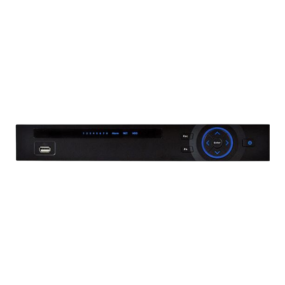
Page 6: Front Panel
6. Connect the HDD cable and 4. Turn the device upside down Fix the HDD firmly. and then turn the screws in power cable. firmly. 7. Put the cover in accordance 8. Secure the screws in the with the clip and then place the rear panel and the side panel. - Page 7 … Shift In textbox, click this button to switch between numeral, English (Small/Capitalized), donation and etc. Enable or disable tour. Fast play Various fast speeds and normal playback. Slow play Multiple slow play speeds or normal playback. Play/Pause In backward playback or pause mode, click this button to go normal playback.
-
Page 8: Rear Panel
Record light 1-16 For 4/8/16 channel device: indication light on means that the channel is in recording. Power indication Power Power indication light. light abnormal HDD error occurs or HDD capacity is below specified indication light threshold value, the light becomes red to alert you. Network abnormal Network error occurs or there is no network connection, indication light... -
Page 9: Connection Sample
Power socket GND port On/off button When connect the Ethernet port, please use crossover cable to connect the PC and use the straight cable to connect to the switcher or router. 1.7 Connection Sample Please note the following introduction is based on the general 1U series only. For detailed information, please refer to our resource CD included in your package for electronic version of the User’s Manual. -
Page 10: Alarm Input And Output Details
Please note the following introduction is based on the general 1U series only. For detailed information, please refer to our resource CD included in your package for electronic version of the User’s Manual. There are two alarm input types for you to select: normal open (NO) and normal close (NC). 1.8.1 Alarm Input and Output Details AB cable AB cable... -
Page 11: Alarm Output Port
Figure 1-6 1.8.3 Alarm Output Port Provide external power to external alarm device. To avoid overloading, please read relay parameters sheet in the User’s Manual carefully. RS485 A/B cable is for the A/B cable of the PTZ decoder. 2 Overview of Navigation and Controls Before operation, please make sure: You have properly installed HDD and all the cable connections. -
Page 12: Main Menu
The system login interface is shown as in Figure 2- 2. System consists of four accounts: Username: admin. Password: admin. (administrator, local and network) Username: 888888. Password: 888888. (administrator, local only) Username: 666666. Password: 666666(Lower authority user who can only monitor, playback, backup and etc.) Username: default. -
Page 13: Auto Resume After Power Failure
In the main menu, click shutdown button, you can see an interface is shown as below. See Figure 2-4. Figure 2-4 There are several options for you. See Figure 2-5. Figure 2-5 The other ways is to press power button on the front panel for at least 3 seconds, system will stop all operations. - Page 14 — Support playback, pause and exit function. — Right now, system does not support slow playback and backward playback function. Support digital zoom function. Support real-time backup function. You can follow the contents listed below for the operation instruction. Preview control interface Move you mouse to the top centre of the video of current channel, you can see system pops up the preview control interface.
-
Page 15: Manual Record
Please note the tour function has the higher priority than the preview playback. You can not control the preview playback until the tour function ended. 2.3 Manual Record Note: You need to have proper rights to implement the following operations. Please make sure the HDD has been properly installed. -
Page 16: Stop All Channel Recording
Highlight ○ below All, you can enable all channel recording. All channel schedule record Please highlight “ALL” after “Schedule”. See Figure 2-9. When system is in schedule recording, all channels will record as you have previously set (Main menu->Setting->Schedule). The corresponding indication light in front panel will turn on. All channel manual record Please highlight “ALL”... -
Page 17: Search & Playback
2.4 Search & Playback Click search button in the main menu, search interface is shown as below. See Figure 2-12. Usually there are three file types: R: Regular recording file. A: External alarm recording file. M: Motion detection recording file. Figure 2-12 Please refer to the following sheet for more information. - Page 18 — In 4-window playback mode: you can select 4 channels according to your requirement. channel — In 9-window playback mode, you can switch between 1-8 and 9-16 channels. selection — In 16-window playback mode, you can switch between1-16 and 17-32 pane.
- Page 19 play 1,fast play 2 and etc. Note: The actual play speed has relationship with the software version. Smart search The volume of the playback Click the snapshot button in the full-screen mode, the system can snapshot 1 picture. System supports custom snap picture saved path. Please connect the peripheral device first, click snap button on the full-screen mode, you can select or create path.
-
Page 20: Smart Search
You can not operate clip operation if there is any file has been checked in the file list. Record In any play mode, the time bar will change once you modify the search type. type Other Functions When system is playing, you can select a zone in the window to begin smart search. -
Page 21: Accurate Playback By Time
Click the , you can go to the smart search playback. Click it again, system stops smart search playback. Important System does not support motion detect zone setup during the full-screen mode. During the multiple-channel playback, system stops playback of rest channels if you implement one-channel smart search. - Page 22 Figure 2-15 Playback Mark During 1-window playback mode, click mark file list button in Figure 2-12, you can go to mark file list interface. Double click one mark file, you can begin playback from the mark time. Play before mark time Here you can set to begin playback from previous N seconds of the mark time.
-
Page 23: Multiple-Channel Preview
Note After you go to the mark management interface, system needs to pause current playback. System resumes playback after you exit mark management interface. If the mark file you want to playback has been removed, system begin playbacking from the first file in the list. -
Page 24: Quick Setup
Please highlight icon to select the corresponding function. After completing all the setups please click save button, system goes back to the previous menu. At the bottom of the menu, there are color bars for your reference. Green color stands for regular recording, yellow color stands for motion detection and red color stands for alarm recording. -
Page 25: Redundancy
Please note, if you select ALL in Figure 2-20, the record setup of all channels are the same and the Copy button becomes hidden. Figure 2-20 2.5.2 Redundancy Redundancy function allows you to memorize record file in several disks. When there is file damage occurred in one disk, there is a spare one in the other disk. -
Page 26: Snapshot
There are two ways for you to playback or search in the redundant disk. Set redundant disk(s) as read-only disk or read-write disk (Main menu->Advanced->HDD management). See Figure 2-21.System needs to reboot to get setup activated. Now you can search or playback file in redundant disk. Dismantle the disk and play it in another PC. -
Page 27: Priority
In Encode interface, click snapshot button to input snapshot mode, size, quality and frequency. See the interface on the left of Figure 2-23. In FTP interface please input upload interval. See the interface in the middle of Figure 2-22. In Detect interface please enable snapshot function for specified channels (interface in the middle of Figure 2-23). -
Page 28: Network
Please input the corresponding information here, if you just upload the image FTP. Figure 2-24 2.7 Network Here is for you to input network information. The single network adapter interface is shown as in Figure 2-25 and the dual network adapters interface is shown as in Figure 2-26. - Page 29 adapter reboot and network becomes off. That is to say, MTU modification can affect current network service. System may pop up dialog box for you to confirm setup when you want to change MTU setup. Click OK button to confirm current reboot, or you can click Cancel button to terminate current modification.
-
Page 30: Network Setting
Figure 2-26 2.7.1 Network Setting Network setting interface is shown as in Figure 2-27. Please check the box to enable corresponding function and then double click current item to go to setup interface. Figure 2-27 2.8 Pan/Tilt/Zoom Please note: Slight difference may be found in the user’s interface, due to various protocols. Please make sure the speed domes A/B cables are properly connected to the A/B ports of DVR. -
Page 31: Ptz Setup
2.8.1 PTZ Setup The pan/tilt/zoom setup includes the following items. Please select channel first. See Figure 2-28. Protocol: Select corresponding PTZ protocol such as PELCOD. Address: Input corresponding PTZ address. Baud rate: Select baud rate. Data bit: Select data bit. Default value is 8. Stop bit: Select stop bit. -
Page 32: Intelligent Positioning Key
Click icon to adjust zoom, focus and iris. Figure 2-30 Figure 2-31 In Figure 2-30, please click direction arrows (See ) to adjust PTZ position. There are total 8 direction arrows. Please note if you use remote control, you can use just four directions (Up/down/left/right). -
Page 33: Web Operation
3 Web Operation Slightly difference may be found in the interface due to different series. 3.1 Network Connection Before web client operation, please check the following items: Network connection is right DVR and PC network setup is right. Please refer to network setup(main menu->setting- >network) Use order ping ***.***.***.***(* DVR IP address) to check connection is OK or not. -
Page 34: Main Window
3.3 Main Window 3.3.1 LAN Login For the LAN mode, after you logged in, you can see the main window. See Figure 3-2. Click the channel name on the left side; you can view the real-time video. Figure 3-2 3.3.2 WAN Login In WAN mode, after you logged in, the interface is shown as below. -
Page 35: Appendix Toxic Or Hazardous Materials Or Elements
Appendix Toxic or Hazardous Materials or Elements Toxic or Hazardous Materials or Elements Component Name Cr VI PBDE Sheet ○ ○ ○ ○ ○ ○ Metal(Case) Plastic Parts ○ ○ ○ ○ ○ ○ (Panel) ○ ○ ○ ○ ○ ○...
Need help?
Do you have a question about the VRHT and is the answer not in the manual?
Questions and answers