Table of Contents
Advertisement
Quick Links
Advertisement
Table of Contents

Related Manuals for Optiview VR LT


Summary of Contents for Optiview VR LT
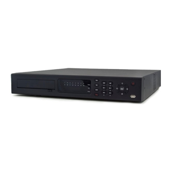
- Page 1 QUICK STARTUP GUIDE VR Series Embedded DVR Systems VR LT VR EM VR PRO...
-
Page 2: Table Of Contents
Table of Contents Hardware Installation and Connection ................5 Unpacked and Check the DVR ................5 About Front Panel and Real Panel ..............5 Cables and Settings ..................... 5 HDD Installation ....................5 1.4.1 2 or 4 HDD Series ..................5 1.4.2 2 HDD Series .................... - Page 3 2.3.1 Manual Record ..................16 2.3.2 Encode ....................... 17 2.3.3 Snapshot ....................17 2.3.4 Image FTP ....................19 2.3.5 Snapshot Disk (For selected series only) ..........19 2.3.6 Search and Playback ................20 2.3.7 Basic Operation ..................21 Network Setup ..................... 22 Pan/Tilt/Zoom ......................
- Page 4 Welcome!!! Thank you for purchasing Optiview VR Embedded DVR Series. This quick startup guide will help you become familiar with DVR basic functionalities. Some of the topic includes hard drive installation, cable connection and general operations such as system setup, record, search, backup, alarm setup, PTZ operation, and remote access through the network.
-
Page 5: Hardware Installation And Connection
For detail information of the function keys at the front and rear panels, please refer to the User’s Manual included in the resource CD. 1.3 Cables and Settings Your DVR system was already pre-inspected at the Optiview OEM facilities where all the settings and cables were already checked and verified by a service technician. 1.4 HDD Installation Hard drive is already pre-installed on your DVR system. -
Page 6: Hdd Series
4. Unfasten the HDD power 5. Use the special data cable to 6. Insert the HDD power cable. Close the cable. connect the HDD and the SATA port chassis and fix the screws to secure firmly. After completing HDD installation, please check connection of data ribbon and power cord. 1.4.2 2 HDD Series This series DVR supports 2 HDDs. - Page 7 Please refer to the following sheet for front panel button information. Name Icon Function Power button, press this button for three seconds to boot up or shut Power button down DVR. To connect USB storage device, USB mouse. USB port Activate current control, modify setup, and then move up and down.
-
Page 8: Rear Panel
IR Receiver CD-ROM button Pop-up or insert the CD. 1.7 Rear Panel 1.7.1 DVR Rear Panel 4/8CH LT series rear panel 4-8CH VR LT Series Video input Audio input Video CVBS output Audio output Network port USB port Video VGA output... - Page 9 EM series DVR rear panel is shown as below. See Figure 1-4. Figure 1-4 VR EM Series Rear Panel Video input Audio input Audio output Video CVBS output USB port Network port HDMI port RS232 port Video VGA output Alarm input/alarm output/RS485 port Power button Power socket PRO Series DVR rear panel is shown as below.
-
Page 10: Connection Sample
1.8 Connection Sample: Refer to the following figure for sample connection 1.8.1 LT Series 1.8.2 EM Series... -
Page 11: Pro Series
1.8.3 PRO Series 1.9 Alarm Input and Output Connections 1.9.1 Alarm Input Port 4/8/16-ch grounding alarm inputs. (Normal open or Normal close type) Please parallel connect COM end and GND end of the alarm detector (Provide external power to the alarm detector). - Page 12 485 A/B 485 communication port. They are used to control devices such as PTZ. Please parallel connect 120Ω between RS485 A/B cables if there are too many PTZ decoders. For VR16LT DVR System RS485 Connection port for PTZ camera (Alarm) Rear Panel for VR16LT DVR System Parameter Grounding Alarm Ground line...
-
Page 13: Alarm Output Port
In the first line, from the left to ALARM 1 to ALARM 16. The alarm becomes active in low voltage. the right,: 1,2,3,4,5,6, 7,8,9,10,11,12,13, 14,15,16 In the second line, from the left The first four are four groups of normal open activation output (on/off button) to the right: NO5 C5 NC5 is a group of NO/NC activation output (on/off button) C1,... -
Page 14: Overview Of Navigation And Controls
Note: Three times login failure within 30 minutes will result in DVR system alarm and five times login failure will result in account lock out. Optiview is not responsible in case you lose your own personalized password. 2.1.2 Main Menu After you logged in, the system main menu is shown as below. -
Page 15: Logout
Figure 2-2 2.1.3 Logout There are two ways for you to log out. You can use the OSD menu or the power button of the DVR system. Logout Option 1: from the main menu, click shutdown button, select “logout….” from the drop-down box then click OK. -
Page 16: Manual Record
In the main menu, you can go to schedule menu. See Figure 2-5. Channel: Please select the channel number first. You can select “all” if you want to set for all the channels. Week day: There are eight options: ranging from Saturday to Sunday and “All”. ... -
Page 17: Encode
2.3.2 Encode Encode interface is shown as in Figure 2-7. Channel: Select the channel you want. Compression: System supports H.264. Resolution: System supports various resolutions, you can select from the dropdown list. For this model, main stream supports D1/HD1/BCIF/CIF/QCIF. Please note the extra stream resolution may vary depending on series model. - Page 18 Figure 2-8 2.3.3.2 Activation Snapshot Please follow the steps listed below to enable the activation snapshot function. After you enabled this function, DVR system can take snapshot when a corresponding alarm occurred. In Encode interface, click snapshot button to input snapshot mode, size, quality and frequency. ...
-
Page 19: Image Ftp
2.3.3.3 Priority The “Activation snapshot” has a higher priority than a “Scheduled Snapshot”. When both snapshot options are enabled and an alarm occurs, the Activation snapshot will supersede the Scheduled Snapshot. 2.3.4 Image FTP In Network interface, you can set FTP server information. Please enable FTP function and then click save button. -
Page 20: Search And Playback
Select a file and then click here to view Select search image content. engine here There are max 100 files in one page. Click here to view more. You can see result here. Double click file name, you can view the image content Figure 2-12 2.3.6... -
Page 21: Basic Operation
Please refer to the following sheet for more information. Serial Number Function Play Backward Stop Slow play Fast play Previous frame Next frame Volume Previous file Next channel Next file Previous channel Search Backup Clip 2.3.7 Basic Operation 2.3.7.1 Playback Operation There are various search modes: video type, channel number or time. -
Page 22: Network Setup
2.3.7.7 Calendar Click calendar icon in Figure 2-13, system pops up a calendar for your reference. The highlighted date indicates there are record files on that day. You can click blue date to view file list. In the figure below, there are video files on June 13th and 14th. Simply double click the date to view file list. Figure 2-14 2.3.7.8 Slow playback and fast playback Please refer to the following sheet for slow play and fast playback function. -
Page 23: Pan/Tilt/Zoom
IP address: input IP(network) address. It could be a private or public network address. Check with your Internet service provider or your private router setup. DHCP: It is auto search IP function. When DHCP is enabled, you cannot modify IP/Subnet mask /Gateway. These values are automatically assigned by the router through DHCP function. -
Page 24: Ptz Setup
2.5.1 PTZ Setup The pan/tilt/zoom setup includes the following steps. First, select camera channel. See Figure 2-16. Protocol: Select corresponding PTZ protocol such as PELCOD. Address: Input corresponding PTZ address. Baud rate: Select baud rate. Data bit: Select data bit. Default value is 8. ... -
Page 25: Intelligent Positioning Key
In Error! Reference source not found., please click direction arrows (See Figure 2-19) to adjust PTZ position. There are total 8 direction arrows. Please note if you use remote control, you can use just four directions (Up/down/left/right). The speed value ranges from 1 to 8. Figure 2-19 2.5.3 3D Intelligent Positioning Key... -
Page 26: Web Operation
Web Operation VR Embedded DVR systems can be accessed remotely on a local network or via Internet using Internet Explorer. 3.1 Network Connection Check the following before making a remote web client access operation: Physical network connection has been setup. ... -
Page 27: Main Window
3.3 Main Window After you logged in, you can see the main window. See Figure 3-2. Click the channel name on the left side; you can view the real-time video. For detailed operation information, please refer to the User’s Manual included in the resources CD. Figure 3-2 Note ...
Need help?
Do you have a question about the VR LT and is the answer not in the manual?
Questions and answers