
Related Manuals for Keithley 2016


Summary of Contents for Keithley 2016
- Page 1 Model 2016 THD Multimeter User’s Manual 2016-900-01 Rev. C / August 2003 G R E A T E R M E A S U R E C O N F I D E N C E...
- Page 3 Model 2016 THD Multimeter User’s Manual ©1999, Keithley Instruments, Inc. All rights reserved. Cleveland, Ohio, U.S.A. Third Printing, August 2003 Document Number: 2016-900-01 Rev. C...
- Page 4 Revision B (Document Number 2016-900-01) ............December 2001 Revision C (Document Number 2016-900-01) ............August 2003 All Keithley product names are trademarks or registered trademarks of Keithley Instruments, Inc. Other brand names are trademarks or registered trademarks of their respective holders.
-
Page 5: Safety Precautions
Service personnel are trained to work on live circuits, perform safe installations, and repair products. Only properly trained service personnel may perform installation and service procedures. Keithley Instruments products are designed for use with electrical signals that are rated Measurement Category I and Measurement Category II, as described in the International Electrotechnical Commission (IEC) Standard IEC 60664. - Page 6 (note that selected parts should be purchased only through Keithley Instruments to maintain accuracy and functionality of the product). If you are unsure about the applicability of a replacement component, call a Keithley Instruments office for information.
-
Page 7: Table Of Contents
Table of Contents General Information Introduction ................Feature overview ................ Warranty information ..............Manual addenda ................. Safety symbols and terms ............Specifications ................Inspection ................... Options and accessories ............. General purpose probes ............Low thermal probes ............Cables and adapters ............. Rack mount kits .............. - Page 8 Measuring frequency and period ..........2-24 Trigger level ..............2-24 Gate time ................2-24 Connections ............... 2-25 Measuring temperature ............. 2-26 Connections ............... 2-26 Configuration ..............2-27 Math ..................2-27 MX + B ................2-28 Percent ................2-29 dBm calculation ..............2-30 dB calculation ..............
- Page 9 Scan operations ................ 3-21 Scanning overview ............3-21 Front panel scanner controls ..........3-21 Stepping and scanning trigger model additions ....3-21 Using SHIFT-CONFIG to configure stepping and scanning ..............3-23 Scanning examples ............3-24 System operations ..............3-26 Calibration ................. 3-26 Remote Operation Introduction ................
- Page 10 Programming syntax ..............4-27 Command words ............... 4-27 Query commands ............... 4-29 Case sensitivity ..............4-29 Long-form and short-form versions ........4-29 Short-form rules ..............4-30 Program messages ............. 4-30 Response messages ............4-33 Message exchange protocol ..........4-33 Common commands ..............4-34 *CLS —...
- Page 11 OUTPut subsystem ..............5-34 ROUTe subsystem ..............5-36 [SENSe[1]] subsystem ............. 5-37 :FUNCtion command ............5-37 :DATA command .............. 5-38 :HOLD command .............. 5-38 Speed commands .............. 5-39 :RANGe commands ............5-40 :REFerence <n> commands ..........5-42 :DIGits command .............. 5-44 :AVERage commands ............
- Page 12 One-shot triggering ............Generating SRQ on buffer full ........... Storing readings in buffer ........... Taking readings using the :READ? command ....Controlling the Model 2016 via the RS-232 COM2 port ... IEEE-488 Bus Overview Introduction ................Bus description ................Bus lines ..................
- Page 13 Bus commands ................Uniline commands ............. Universal multiline commands .......... Addressed multiline commands ........D-10 Address commands ............D-10 Unaddress commands ............D-10 Common commands ............D-11 SCPI commands ............... D-11 Command codes ............... D-11 Typical command sequences ........... D-13 IEEE command groups ............
- Page 15 Remote Operation Figure 4-1 RS-232 interface connector ........... Figure 4-2 IEEE-488 connector ............... Figure 4-3 IEEE-488 connections ............Figure 4-4 IEEE-488 connector location ..........Figure 4-5 Model 2016 status register structure ........4-16 Figure 4-6 Standard event status ............4-18...
- Page 16 Figure 4-7 Operation event status ............4-19 Figure 4-8 Measurement event status ............ 4-19 Figure 4-9 Questionable event status ............. 4-20 Figure 4-10 Status byte and service request (SRQ) ......... 4-21 Figure 4-11 Trigger model (remote operation) ........4-24 Figure 4-12 Device action (trigger model) ..........
- Page 17 List of Tables Basic Measurements Table 2-1 Fuse ratings ................Table 2-2 Factory defaults ..............2-13 Measurement Options Table 3-1 Rate settings for the measurement functions ......Table 3-2 Auto delay settings ..............Remote Operation Table 4-1 RS-232 connector pinout ............Table 4-2 General bus commands and associated statements ....
- Page 18 Table D-4 Typical addressed command sequence ........ D-13 Table D-5 IEEE command groups ............D-14 Table D-6 Model 2016 interface function codes ........D-15 IEEE-488 and SCPI Conformance Information Table E-1 IEEE-488 documentation requirements ........ Table E-2 Coupled commands ...............
- Page 19 General Information General Information...
-
Page 20: General Information
DC voltage accuracy and 0.008% 90-day basic resistance accuracy. At 6 -digits, the multimeter delivers 50 triggered readings/sec over the IEEE-488 bus. At 4 -digits, it can read up to 2000 readings/sec into its internal buffer. The Model 2016 has broad measurement ranges: •... -
Page 21: Warranty Information
Warranty information Warranty information is located at the front of this instruction manual. Should your Model 2016 require warranty service, contact the Keithley representative or authorized repair facility in your area for further information. When returning the instrument for repair, be sure to fill out and include the service form at the back of this manual to provide the... -
Page 22: Inspection
• Certificate of calibration. • Product Information CD-ROM that contains a PDF of the Model 2016 User's Manual. If an additional manual is required, order the appropriate manual package. The manual packages include a manual and any pertinent addenda. Options and accessories The following options and accessories are available from Keithley for use with the Model 2016. -
Page 23: Low Thermal Probes
BNC trigger connectors. The Model 8504 is 1m long. Rack mount kits Model 4288-1 Single Fixed Rack Mount Kit: Mounts a single Model 2016 in a standard 19-inch rack. Model 4288-2 Side-by-Side Rack Mount Kit: Mounts two instruments (Models 182, 428, 486, 487, 2000, 2001, 2002, 2010, 2015, 2016, 6514, 6517, 7001) side-by-side in a standard 19-inch rack. - Page 24 General Information...
-
Page 25: Basic Measurements
Basic Mea- surements Basic Measurements... -
Page 26: Introduction
Basic Measurements Introduction This section summarizes front panel operation of the Model 2016. It is organized as follows: • Front panel summary — Includes an illustration and summarizes keys, display, and connections. • Rear panel summary — Includes an illustration and summarizes connections. -
Page 27: Front Panel Summary
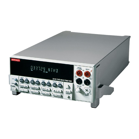
Basic Measurements Front panel summary The front panel of the Model 2016 is shown in Figure 2-1. This figure includes important abbreviated information that should be reviewed before operating the instrument. Figure 2-1 SENSE Model 2016 INPUT Ω 4 WIRE... -
Page 28: Basic Measurements
Basic Measurements Shifted operation keys DELAY Sets user delay between trigger and measurement. HOLD Holds reading when the selected number of samples is within the selected tolerance. LIMITS Sets upper and lower limit values for readings. ON/OFF Enables/disables limits; selects beeper operation for limit testing. TEST Selects built-in tests, diagnostics, display test. -
Page 29: Basic Measurements
Basic Measurements Input connections INPUT HI and LO Used for making DC volts, AC volts, 2-wire resistance measurements. AMPS Used in conjunction with INPUT LO to make DC current and AC current measurements. Also holds current input fuse (3A, 250V, fast blow, 5×20mm). -
Page 30: Rear Panel Summary
Basic Measurements Rear panel summary The rear panel of the Model 2016 is shown in Figure 2-2. This figure includes important abbreviated information that should be reviewed before operating the instrument. Figure 2-2 Model 2016 rear panel MADE IN U.S.A. - Page 31 Connector for IEEE-488 (GPIB) operation. Use a shielded cable, such as Models 7007-1 and 7007-2. Power module Contains the AC line receptacle, power line fuse, and line voltage setting. The Model 2016 can be configured for line voltages of 100V/120V/220V/240VAC at line frequencies of 45Hz to 66Hz.
-
Page 32: Power-Up
Basic Measurements Power-up Line power connection Follow the procedure below to connect the Model 2016 to line power and turn on the instrument. Check to see that the line voltage selected on the rear panel (see Figure 2-3) is correct for the operating voltage in your area. -
Page 33: Setting Line Voltage And Replacing Fuse
If the instrument repeatedly blows fuses, locate and correct the cause of the trouble before replacing the fuse. See the Model 2016 Service Manual for troubleshooting information. If configuring the instrument for a different line voltage, remove the line voltage selector from the assembly and rotate it to the proper position. -
Page 34: Power-Up Sequence
Basic Measurements Power-up sequence On power-up, the Model 2016 performs self-tests on its EPROM and RAM and momentarily lights all segments and annunciators. If a failure is detected, the instrument momentarily displays an error message and the ERR annunciator turns on. (Error messages are listed in Appendix B.) -
Page 35: High Energy Circuit Safety Precautions
Basic Measurements 2-11 High energy circuit safety precautions To optimize safety when measuring voltage in high energy distribution circuits, read and use the directions in the following warning. WARNINGS Dangerous arcs of an explosive nature in a high energy circuit can cause severe personal injury or death. -
Page 36: Power-On Defaults
Power-on defaults are the settings the instrument assumes when it is turned on. The Model 2016 offers two choices for the settings: factory and user. The power-on default will be the last configuration you saved. The SAVE and SETUP keys select the two choices of power-on defaults. -
Page 37: Table 2-2 Factory Defaults
Basic Measurements 2-13 Table 2-2 Factory defaults Setting Factory default Autozero Buffer No effect Continuity Beeper Digits Rate Fast (0.1 PLC) Threshold 10Ω Current (AC and DC) Digits (AC) Digits (DC) Filter Count Mode Moving average Range Auto Relative Value Rate (AC) Medium* Rate (DC) - Page 38 2-14 Basic Measurements Table 2-2 (cont.) Factory defaults Setting Factory default GPIB No effect Address (16 at factory) Limits Beeper Never High limit Low limit mX+b Scale factor Offset Percent References Resistance (2-wire and 4-wire) Digits Filter Count Mode Moving average Range Auto Relative...
-
Page 39: Gpib Primary Address
See Section Four — Remote Operation for more GPIB information. Warm-up time The Model 2016 is ready for use as soon as the power-up sequence has completed. However, to achieve rated accuracy, allow the instrument to warm up for one hour. If the instrument has been subjected to extreme temperatures, allow additional time for internal temperatures to stabilize. -
Page 40: Display
Basic Measurements Display The display of the Model 2016 is primarily used to display readings, along with the units and type of measurement. Annunciators are located on the top, bottom, right, and left of the reading or message display. The annunciators indicate various states of operation. See... -
Page 41: Crest Factor
Effects not noticeable when working with higher voltages are significant in microvolt signals. The Model 2016 reads only the signal received at its input; therefore, it is important that this signal be properly transmitted from the source. The following paragraphs indicate factors... -
Page 42: Thermal Emfs
Therefore, to minimize AC interference, the circuit should be shielded with the shield connected to the Model 2016 INPUT LO (particularly for low level sources). Improper shielding can cause the Model 2016 to behave in one or more of the following ways: •... -
Page 43: Ac Voltage Offset
2-19 AC voltage offset The Model 2016, at 5 -digits resolution, will typically display 100 counts of offset on AC volts with the input shorted. This offset is caused by the offset of the TRMS converter. This offset will not affect reading accuracy and should not be zeroed out using the REL feature. The... -
Page 44: Measuring Current
2-20 Basic Measurements Measuring current The Model 2016 can make DCI measurements from 10nA to 3A and ACI measurements from 1µAm to 3A RMS. NOTE See the previous discussion about crest factor in “Measuring voltage” in this section. Connections Assuming factory default conditions, the basic procedure is as follows: Connect test leads to the AMPS and INPUT LO terminals. -
Page 45: Amps Fuse Replacement
If the instrument repeatedly blows fuses, locate and correct the cause of the trouble before replacing the fuse. See the Model 2016 Service Manual for troubleshooting information. Install the new fuse by reversing the procedure above. See Section 3 — Measurement Options for information that explains the configuration... -
Page 46: Measuring Resistance
2-22 Basic Measurements Measuring resistance The Model 2016 can make 2-wire and 4-wire resistance measurements from 100µΩ to 120MΩ. Connections Assuming factory default conditions, the basic procedure is as follows: Connect test leads to the Model 2016 as follows: A. For Ω2-wire, connect the test leads to INPUT HI and LO. -
Page 47: Shielding
TALK REAR LSTN SHIFT 350V 1000V TIMER HOLD TRIG FAST SLOW FILT AUTO BUFFER STAT PEAK PEAK 2016 THD MULTIMETER 500V MATH T H D CONT PERIOD TCOUPL PEAK INPUTS Ω2 Ω4 SHIFT FREQ TEMP RANGE Resistance DELAY HOLD LIMITS... -
Page 48: Measuring Frequency And Period
The multimeter’s AC voltage measurement section performs input signal conditioning. Gate time The gate time is the amount of time the Model 2016 uses to sample frequency or period readings. The RATE key setting yields gate times as follows: FAST = 0.01s MEDium = 0.1s... -
Page 49: Connections
Assuming factory default conditions, the basic procedure is as follows: Connect test leads to the INPUT HI and LO terminals of the Model 2016. Either the front or rear inputs can be used; place the INPUTS button in the appropriate position. -
Page 50: Measuring Temperature
2-26 Basic Measurements Measuring temperature The Model 2016 measures temperature with thermocouples. The temperature measurement ranges available depend on the type of thermocouple chosen. Thermocouples can be connected to an external thermocouple card, such as a Model 7057A, 7402, or 7014 installed in a Model 7001 or 7002 Switch System. -
Page 51: Configuration
Configure the parameters for the math operation. Press ENTER when done. (Press SHIFT then the related math function to end the calculation.) NOTES Once enabled for a function, the mX+b and percentage calculations are in effect across function changes. The Model 2016 uses IEEE-754 floating point format for math calculations. -
Page 52: Mx + B
B: +00.00000 m Enter a value and units prefix. Press ENTER to confirm the B value and display the UNITS designation: Scroll through the letters to change and press ENTER when done. The Model 2016 then displays the result of the calculation. -
Page 53: Percent
Press ENTER when done. The Model 2016 will display the result of the calculation. The result is positive when the input exceeds the reference and negative when the input is less than the reference. Engineering units are used to show values in the range 1 nano to 1000G. -
Page 54: Dbm Calculation
1mW reference. With a user-programmable reference impedance, the Model 2016 reads 0dBm when the voltage needed to dissipate 1mW through the reference impedance is applied. The relationship between dBm, a reference impedance, and the voltage is defined by the following equation:... -
Page 55: Db Calculation
Basic Measurements 2-31 dB calculation Expressing DC or AC voltage in dB makes it possible to compress a large range of measurements into a much smaller scope. The relationship between dB and voltage is defined by the following equation: dB= 20 log ----------------- - where: V is the DC or AC input signal. -
Page 56: Measuring Continuity
The Model 2016 uses the 1kΩ range to measure circuit continuity. After selecting continuity, the unit prompts you for a threshold resistance level (1Ω-1000Ω). The Model 2016 alerts you with a beep when a reading is below the set level. -
Page 57: Testing Diodes
The diode test measures voltages on the 3V range for the 1mA test current and the 10V range for the 100µA and 10µA ranges. If a reading is more than 10V, the Model 2016 displays the “OVERFLOW” status message. -
Page 58: Measuring Distortion
The Model 2016 can make distortion measurements from 0.002% to 100% (-94dB to 0dB). The 2016 uses a digital signal processor (DSP) to perform a fast Fourier transform on the signal applied to the front or rear voltage inputs. It then analyzes the levels of the harmonics present in the signal to calculate THD, THD+noise, and SINAD. -
Page 59: Configuration
;select THD, THD+n, or SINAD Set the distortion frequency acquisition The Model 2016 must know the fundamental frequency of the input waveform. Even a difference of a few hertz can cause large errors. The choices are AUTO, SET, and ACQUIRE. - Page 60 :UNIT:DISTortion PERCent|DB ;select percent or dB for units Select shaping filter The Model 2016 has digital shaping filters to simulate having the sample signal pass through various types of telephone lines. The filter is turned off by default (NONE). Press THD-MEAS.
- Page 61 The Model 2016 has a 10Hz-20kHz (60Hz default) two-channel function generator. It can be used to evaluate amplifiers, filters or other devices, or can be connected to the 2016 inputs. The function generator has selectable output impedances of 50Ω, 600Ω, and HIZ (50Ω default), and is unbalanced (coaxial).
- Page 62 Retrieve magnitude of individual harmonic (remote operation only) The 2016 can return the levels of individual harmonics (relative to the level of the fundamental, in dB). The parameters for this command are the starting and ending harmonics. Specify 2,3 for the second and third harmonics, or 2,2 for the second harmonic. The harmonic levels returned correspond to the last triggered reading, and the unit has to be set for one-shot readings (:INIT:CONT OFF).
- Page 63 Configuring and using the internal sweep (remote operation only) The Model 2016's internal source can be set to sweep up to 200 frequencies and then return the distortion and/or RMS volts for each frequency. Sweep results can be returned using the SREAL data format (fastest—IEEE754 single precision), DREAL data format (IEEE754...
-
Page 64: Connections
Configuring high and low cutoff filters (remote operation only) The Model 2016 includes low and high cutoff filters used to limit the range of frequencies used in distortion measurements. The filters can be set in the range of 20Hz to 50kHz. Use the low cutoff to limit noise frequencies below the fundamental for THD+noise and SINAD measurements (the low filter does not have an effect in THD mode). -
Page 65: Figure 2-11 Distortion Measurements
TALK LSTN SHIFT Source 350V 1000V TIMER HOLD TRIG FAST SLOW FILT AUTO BUFFER STAT PEAK PEAK 2016 THD MULTIMETER 500V MATH T H D CONT PERIOD TCOUPL PEAK INPUTS Ω2 Ω4 SHIFT FREQ TEMP RANGE DELAY HOLD LIMITS ON/OFF... -
Page 66: Measurement Examples
NOTE The Rel key is not supported for distortion measurements. Turn on the Model 2016 and connect the function generator output (SOURCE OUTPUT) to the front or rear voltage inputs (INPUT HI/LO). Set the INPUTS button accordingly. Press SHIFT then ACV(THD) to put the 2016 into distortion measurement mode. - Page 67 When the display shows “CHAN2:” select ISINE and press ENTER. The display should read approximately 0.2 %THD. To illustrate why the 2016 needs to know the exact source frequency, perform the following: Press THD-MEAS and press ENTER once. When the display shows “FREQ:”, select SET and press ENTER.
- Page 68 2-44 Basic Measurements Measuring AC volts or frequency To measure AC volts or frequency using the Model 2016, follow this procedure. Note that the function generator does not work outside the distortion function. Select ACV or frequency. Front panel: • Press ACV or FREQ.
- Page 69 2-45 Set digital filter for ACV. The 2016 has a digital averaging filter to stabilize readings. The repeating filter takes the set number of readings, averages, then updates the display. The moving filter throws out the oldest reading, takes a new reading, then updates the display. The moving filter updates the display faster, but takes longer for readings to stabilize.
- Page 70 Distortion and RMS volts sweep example This is an example of the bus commands which should be sent to the 2016 to configure1 start, and receive the data for a 10-point sweep. This also includes the use of the high and low cutoff filters.
-
Page 71: Measurement Options
Measure- ment Options Measurement Options... -
Page 72: Introduction
Measurement Options Introduction This section describes the front panel features of the Model 2016. For those measurement options accessible only by a remote interface, refer to Sections 4 and 5. This section is organized as follows: • Measurement configuration — Describes ranging, filtering, relative readings, digits of resolution, and measurement rate. -
Page 73: Filter
The AUTO key has no effect on the temperature, continuity, and diode test functions. Filter FILTER lets you set the filter response to stabilize noisy measurements. The Model 2016 uses a digital filter, which is based on reading conversions. The displayed, stored, or transmitted read- ing is simply an average of a number of reading conversions (from 1 to 100). -
Page 74: Figure 3-1 Moving Average And Repeating Filters
Measurement Options Filter types The moving average filter (Figure 3-1) uses a first-in, first-out stack. When the stack becomes full, the measurement conversions are averaged, yielding a reading. For each subsequent con- version placed into the stack, the oldest conversion is discarded, and the stack is re-averaged, yielding a new reading. -
Page 75: Relative
Digits The display resolution of a Model 2016 reading depends on the DIGITS setting. It has no effect on the remote reading format. The number of displayed digits does not affect accuracy or speed. Those parameters are controlled by the RATE setting. -
Page 76: Rate
Measurement Options Rate The RATE operation sets the integration time of the A/D converter, the period of time the input signal is measured (also known as aperture). The integration time affects the usable digits, the amount of reading noise, as well as the ultimate reading rate of the instrument. The integration time is specified in parameters based on a number of power line cycles (NPLC), where 1 PLC for 60Hz is 16.67msec and 1 PLC for 50Hz and 400Hz is 20msec. -
Page 77: Table 3-1 Rate Settings For The Measurement Functions
Measurement Options Bandwidth The rate setting for AC voltage and current measurements determines the bandwidth setting: • Slow — 3Hz to 300kHz. • Medium — 30Hz to 300kHz. • Fast — 300Hz to 300kHz. Bandwidth is used to specify the lowest frequency of interest. When the Slow bandwidth (3Hz to 300kHz) is chosen, the signal goes through an analog RMS converter. -
Page 78: Trigger Operations
• A bus trigger (GET or *TRG) is received. • The front panel TRIG key is pressed. (The Model 2016 must be taken out of remote before it will respond to the TRIG key. Use the LOCAL key or send LOCAL 716 over... -
Page 79: Table 3-2 Auto Delay Settings
A programmable delay is available after event detection. It can be set manually or an auto delay can be used. With auto delay, the Model 2016 selects a delay based on the function and range. The AUTO settings are listed in Table 3-2. -
Page 80: Device Actions
3-10 Measurement Options Device actions The primary device action is a measurement. However, the device action block could include the following additional actions: • Source and Delay (while in LIST mode) — If MODE is set to LIST (rather than FIXED), readings will be taken for each listed amplitude and frequency pair, up to the maximum number of pairs allowed (see :OUTPut:LIST command in Section 5). -
Page 81: Reading Hold (Autosettle)
TRIG key to trigger a single reading. Pressing the EXT TRIG key again toggles you back to continuous triggers. The Model 2016 uses two lines of the Trigger Link rear panel connector as External Trigger (EXT TRIG) input and Voltmeter Complete (VMC) output. The EXT TRIG line allows the Model 2016 to be triggered by other instruments. -
Page 82: Figure 3-4 Trigger Link Input Pulse Specifications (Ext Trig)
In a typical test system, you may want to close a channel and then measure the DUT connected to the channel with a multimeter. Such a test system is shown in Figure 3-6, which uses a Model 2016 to measure ten DUTs switched by a Model 7011 multiplexer card in a Model 7001/7002 Switch System. -
Page 83: Figure 3-6 Dut Test System
Number of scans = 1 Channel spacing = TrigLink To run the test and store readings in the Model 2016 with the unit set for external triggers, press STEP or SCAN. The Model 2016 waits (with the asterisk annunciator lit) for an external... -
Page 84: Figure 3-8 Operation Model For Triggering Example
Press STEP on the Model 7001/7002 to take it out of idle and start the scan. The scanner’s output pulse triggers the Model 2016 to take a reading, store it, and send a trigger pulse. The following explanation on operation is referenced to the operation model shown in Figure 3-8. - Page 85 (point F) and then loops back to point A, where it waits for another input trigger. The trigger applied to the Model 7001/7002 from the Model 2016 closes the next channel in the scan. This triggers the multimeter to measure the next DUT. The process continues until all...
-
Page 86: Buffer Operations
Model 2016 Buffer operations The Model 2016 has a buffer to store from two to 1024 readings and units. It also stores the channel number for scanned readings and overflow readings. In addition, recalled data includes statistical information, such as minimum, maximum, average, and standard deviation. -
Page 87: Storing Readings
Measurement Options 3-17 Storing readings Use the following procedure to store readings: Set up the instrument for the desired configuration. Press the STORE key. Using the , and keys, select the number of readings desired. Press ENTER. The asterisk (*) annunciator turns on to indicate a data storage operation. It will turn off when the storage is finished. -
Page 88: Buffer Statistics
NOTE The Model 2016 uses IEEE-754 floating point format for math calculations. Limit operations Limit operations set and control the values that determine the HI / IN / LO status of subsequent measurements. -
Page 89: Setting Limit Values
Measurement Options 3-19 Setting limit values Use the following steps to enter high and low limit values: Press the SHIFT-LIMITS keys to view the present HI1 limit value: HI1:+1.000000 This value represents the absolute value of that function. Use the keys to move to the number field. -
Page 90: Enabling Limits
3-20 Measurement Options Enabling limits Use the following procedure to turn on the limits operation: Press the SHIFT-ON/OFF keys to view the present beeper status: BEEP: NEVER Use the keys to change the beeper status (NEVER, OUTSIDE, INSIDE). Press ENTER when done. When the multimeter returns to the normal display, the HI/IN/LO status is displayed along with the reading. -
Page 91: Scan Operations
Model 2016. Scanning overview A scanner lets you switch among a number of input signals to the Model 2016 for measurement. Refer to the documentation supplied with the scanner card for specific connection information. When using external channels, the switching mainframe controls the opening and closing of individual channels. -
Page 92: Figure 3-12 Front Panel Triggering With Stepping
3-22 Measurement Options These additional blocks are shown in the trigger models of Figure 3-12 Figure 3-13. Uses of the timer control source, reading counter, and channel counter are shown in the scanning examples later in this section. Figure 3-12 Idle Front panel triggering with stepping... -
Page 93: Using Shift-Config To Configure Stepping And Scanning
The next selection is for timed scans. (This is the Timer control source in the trigger model.) It sets a user-specified interval for starting scans. If you choose timed scans, the Model 2016 prompts for a time interval: 00H:00M:00.000S Use the , and keys to select a time interval and press ENTER to confirm. -
Page 94: Scanning Examples
When using an external thermocouple scanner card and channel 1 as a reference, the Model 2016 recognizes only channel 1 when a step or scan is performed. If using a Model 7001 or 7002 to close channel 1 manually, the Model 2016 will not interpret... -
Page 95: Figure 3-14 External Scanning Example With Model 7001
Measurement Options 3-25 Figure 3-14 Model 7001 Model 2016 (from “reset setup”) (from “factory setup”) External scanning example with Model 7001 SCAN CHANNELS 1!1-1!10 CONFIGURE SCAN CHAN-CONTROL CHANNEL-SPACING TRIGLINK ASYNCHRONOUS CHAN-COUNT SCAN-CONTROL SCAN-COUNT SHIFT-CONFIG TYPE:EXT MIN CHAN: 001 MAX CHAN: 010... -
Page 96: System Operations
3-26 Measurement Options System operations The Model 2016 has other front panel operations. Saving and restoring setup information is described in Section 2 — Basic Measurements. Selecting the remote interface and language is covered in Section 4 — Remote Operation. - Page 97 Remote Operation Remote Operation...
-
Page 98: Remote Operation
• Programming syntax • Common commands Selecting an interface The Model 2016 THD Multimeter supports two built-in remote interfaces: • GPIB bus • RS-232 interface You can use only one interface at a time. The factory interface selection is the GPIB bus. You can select the interface only from the front panel. -
Page 99: Rs-232
For more information about the RS-232 interface, see section RS-232 operation. GPIB bus The GPIB bus is the IEEE-488 interface. You must select a unique address for the Model 2016 THD Multimeter. The address is displayed when the multimeter is turned on. At the factory, the address is set to 16. -
Page 100: Operation
You can break data transmissions by sending a ^C or ^X character string to the multimeter. This clears any pending operation and discards any pending output. Selecting baud rate The baud rate is the rate at which the Model 2016 THD Multimeter and the programming terminal communicate. Choose one these available rates: •... -
Page 101: Selecting Signal Handshaking (Flow Control)
Selecting signal handshaking (flow control) Signal handshaking between the controller and the instrument allows the two devices to communicate to each other regarding being ready or not ready to receive data. The Model 2016 does not support hardware handshaking (flow control). -
Page 102: Connections
Remote Operation RS-232 connections The RS-232 serial port can be connected to the serial port of a controller (i.e., personal computer) using a straight through RS-232 cable terminated with DB-9 connectors. Do not use a null modem cable. The serial port uses the transmit (TXD), receive (RXD) and signal ground (GND) lines of the RS-232 standard. -
Page 103: Gpib Bus Operation And Reference
GPIB bus standards The GPIB bus is the IEEE-488 instrumentation data bus with hardware and programming standards originally adopted by the IEEE (Institute of Electrical and Electronic Engineers) in 1975. The Model 2016 THD Multimeter conforms to these standards: • IEEE-488-1987.1 •... -
Page 104: Gpib Bus Connections
Remote Operation GPIB bus connections To connect the Model 2016 THD Multimeter to the GPIB bus, use a cable equipped with standard IEEE-488 connectors as shown in Figure 4-2. Figure 4-2 IEEE-488 connector To allow many parallel connections to one instrument, stack the connector. Two screws are located on each connector to ensure that connections remain secure. -
Page 105: Figure 4-4 Ieee-488 Connector Location
Remote Operation To connect the Model 2016 THD Multimeter to the IEEE-488 bus, follow these steps: Line up the cable connector with the connector located on the rear panel. The connector is designed so that it will fit only one way. -
Page 106: Selecting The Primary Address
Remote Operation Selecting the primary address The Model 2016 THD Multimeter ships from the factory with a GPIB address of 16. When the multimeter powers up, it momentarily displays the primary address. You can set the address to a value of 0-30. Do not assign the same address to another device or to a controller that is on the same GPIB bus. - Page 107 Multimeter. If the program message includes a query command, then the ENTER command is required to get the response message from the Model 2016 THD Multimeter. The ENTER command addresses the Model 2016 THD Multimeter to talk. The following example program fragment demonstrates how OUTPUT and ENTER commands are used.
-
Page 108: General Bus Commands
Serial Polls the Model 2016. REN (remote enable) The remote enable command is sent to the Model 2016 by the controller to set up the instrument for remote operation. Generally, the instrument should be placed in the remote mode before you attempt to program it over the bus. Simply setting REN true does not actually place the instrument in the remote state. -
Page 109: Ifc (Interface Clear)
4-13 IFC (interface clear) The IFC command is sent by the controller to place the Model 2016 THD Multimeter in the local, talker, listener idle states. The unit responds to the IFC command by canceling front panel TALK or LSTN lights if the instrument was previously placed in one of those states. -
Page 110: Sdc (Selective Device Clear)
SPE, SPD (serial polling) Use the serial polling sequence to obtain the Model 2016 serial poll byte. The serial poll byte contains important information about internal functions (see “status structure”). Generally, the serial polling sequence is used by the controller to determine which of several instruments has requested service with the SRQ line. -
Page 111: Front Panel Gpib Operation
IFC (Interface Clear) command. • LSTN — This indicator is on when the Model 2016 THD Multimeter is in the listener active state, which is activated by addressing the instrument to listen with the correct MLA (My Listen Address) command. LSTN is off when the unit is in the listener idle state. -
Page 112: Status Structure
Status structure Figure 4-5 for the Model 2016 THD Multimeters status structure. Instrument events, such as errors, are monitored and manipulated by four status register sets. Notice that these status register sets feed directly into the Status Byte Register. More detailed illustrations of these... -
Page 113: Condition Registers
Remote Operation 4-17 Condition registers Figure 4-5 shows, all status register sets have a condition register. A condition register is a real-time, read-only register that constantly updates to reflect the current operating conditions of the instrument. For example, while a measurement is being performed, bit B4 (Meas) of the Operation Condition Register is set. -
Page 114: Figure 4-6 Standard Event Status
4-18 Remote Operation An enable register is not cleared when it is read. The following operations affect the enable registers: • Cycling power - Clears all enable registers • :STATus:PREset clears the following enable registers: Operation Event Enable Register Questionable Event Enable Register Measurement Event Enable Register *ESE 0 - Clears the Standard Event Status Enable Register. -
Page 115: Figure 4-8 Measurement Event Status
Remote Operation 4-19 Figure 4-7 Operation Idle Trig Meas Operation event status Condition Registe (B15 - B11) (B10) (B9) (B8) (B7) (B6) (B5) (B4) (B3) (B2) (B1) (B0) Operation Event Idle Trig Meas Register (B15 - B11) (B10) (B9) (B8) (B7) (B6) (B5) (B4) (B3) (B2) (B1) (B0) &... -
Page 116: Queues
Queue is considered cleared when it is empty. An empty Output Queue clears the MAV bit in the Status Byte Register. Read a message from the Output Queue by addressing the Model 2016 THD Multimeter to talk after the appropriate query is sent. -
Page 117: Status Byte And Service Request (Srq)
Error Queue is considered cleared when it is empty. An empty Error Queue clears the EAV bit in the Status Byte Register. Read an error message from the Error Queue by sending either of the following SCPI query commands and then addressing the Model 2016 to talk: •... -
Page 118: Status Byte Register
4-22 Remote Operation Status byte register The summary messages from the status registers and queues are used to set or clear the appropriate bits (B0, B2, B3, B4, B5, and B7) of the Status Byte Register. These bits do not latch, and their states (0 or 1) are solely dependent on the summary messages (0 or 1). -
Page 119: Serial Poll And Srq
Typically, service requests (SRQs) are managed by the serial poll sequence of the Model 2016. If an SRQ does not occur, bit B6 (RQS) of the Status Byte Register will remain cleared and the program will simply proceed normally after the serial poll is performed. -
Page 120: Trigger Model (Gpib Operation)
4-24 Remote Operation Trigger model (GPIB operation) This section describes how the Model 2016 THD Multimeter operates over the GPIB bus. The flowchart in Figure 4-11 summarizes operation over the bus and is called the trigger model. It is called the trigger model because operation is controlled by SCPI commands from the Trigger subsystem (see Section 5 for more information). -
Page 121: Idle And Initiate
IMMediate — Event detection is immediately satisfied allowing operation to continue. • MANual — Event detection is satisfied by pressing the TRIG key. The Model 2016 THD Multimeter must be in LOCAL mode for it to respond to the TRIG key. Press the LOCAL key or send LOCAL 16 over the bus to remove the instrument from the remote mode. -
Page 122: Figure 4-12 Device Action (Trigger Model)
4-26 Remote Operation Device Action — Figure 4-12 provides a detailed look at the device action. If the repeat filter is enabled, then the instrument samples the specified number of reading conversions to yield a single filtered reading. If the moving filter is active, or filter is disabled, then only one reading conversion is performed. -
Page 123: Programming Syntax
Remote Operation 4-27 Programming syntax The information in this section covers syntax for both common commands and SCPI commands. For information not covered here, see the IEEE-488.2 and SCPI standards. Command words Program messages are made up of one or more command words. Commands and command parameters Common commands and SCPI commands may or may not use a parameter. - Page 124 4-28 Remote Operation • Parameter types: The following are some of the more common parameter types: <b> Boolean: Used to enable or disable an instrument operation. 0 or OFF disables the operation, and 1 or ON enables the operation. Example: :CURRent:AC:RANGe:AUTO ON Enable auto ranging <name>...
-
Page 125: Query Commands
Remote Operation 4-29 Query commands This type of command requests (queries) the currently programmed status. It is identified by the question mark (?) at the end of the fundamental form of the command. Most commands have a query form. Example: :TRIGger:TIMer? Queries the timer interval. -
Page 126: Short-Form Rules
4-30 Remote Operation Short-form rules Use the following rules to determine the short-form version of any SCPI command: • If the length of the command word is four letters or less, no short form version exists. Example: :auto = :auto •... -
Page 127: Single Command Messages
Remote Operation 4-31 Single command messages The above command structure has three levels. The first level is made up of the root command (:STATus) and serves as a path. The second level is made up of another path (:OPERation) and a command (:PRESet). -
Page 128: Command Path Rules
4-32 Remote Operation Command path rules • Each new program message must begin with the root command, unless it is optional (e.g., [:SENSe]). If the root is optional, simply treat a command word on the next level as the root. •... -
Page 129: Response Messages
“Multiple Command Messages”), the multiple response messages for all the queries is sent to the computer when the Model 2016 is addressed to talk. The responses are sent in the order that the query commands were sent and are separated by semicolons (;). Items within the same query are separated by commas (,). -
Page 130: Common Commands
Option identification query Returns an ID code that indicates which option is installed. (0 = no option.) *RCL <NRf> Recall command Returns the Model 2016 to the setup configuration stored in the specified memory location. *RST Reset command Returned the Model 2016 to the *RST default conditions. -
Page 131: Cls - Clear Status
4-35 *CLS — Clear Status Clear status registers and error queue Description Use the *CLS command to clear (reset to 0) the bits of the following registers in the Model 2016: • Standard Event Register • Operation Even Register •... -
Page 132: Esr? - Event Status Register Query
4-36 Remote Operation The Standard Event Enable Register is shown in Figure 4-13 and includes the decimal weight of each bit. The sum of the decimal weights of the bits that you wish to be set is the parameter value that is sent with the *ESE command. For example, to set the CME and QYE bits of the Standard Event Enable Register, send the following command: *ESE 36 Where: CME (bit B5) = Decimal... -
Page 133: Figure 4-14 Standard Event Status Register
Model 2016 front panel was pressed. • Bit B7, Power ON (PON) — A set bit indicates that the Model 2016 has been turned off and turned back on since the last time this register has been read. Figure 4-14... -
Page 134: Idn? - Identification Query
Description On power-up or when the *CLS or *RST is executed, the Model 2016 goes into the Operation Complete Command Idle State (OCIS). In this state, no pending overlapped commands exist. The Model 2016 has three overlapped commands: •... - Page 135 'Wait two seconds GOSUB ReadRegister 'Read register to show that OPC is not set PRINT #1, "output 16; :abort" 'Place 2016 back in idle GOSUB ReadRegister 'Read register to show that OPC is now set ReadRegister: PRINT #1, "output 16; *esr?"...
-
Page 136: Opc? - Operation Complete Query
When used with the :INITiate or :INITiate:CONTinuous ON command, an ASCII “1” will not be sent to the Output Queue and the MAV bit will not set until the Model 2016 goes back into the idle state. The initiate operations are not considered finished until the instrument goes into the idle state. -
Page 137: Opt? - Option Identification Query
Parameters <NRf>=0 Description Use this command to return the Model 2016 to the configuration stored in memory. The *SAV command is used to store the setup configuration in memory location. Only one setup configuration can be saved and recalled. The Model 2016 ships from the factory with :SYSTem:PRESet defaults loaded into the available setup memory. -
Page 138: Rst - Reset
*RST — RESET Return 2016 to *RST defaults Description When the *RST command is sent, the Model 2016 performs the following operations: Returns the Model 2016 to the *RST default conditions (see SCPI tables). Cancels all pending commands. Cancels response to any previously received *OPC and *OPC? commands. -
Page 139: Figure 4-15 Service Request Enable Register
Remote Operation 4-43 This enable register is used along with the Status Byte Register to generate service requests (SRQ). With a bit in the Service Request Enable Register set, an SRQ occurs when the corresponding bit in the Status Byte Register is set by an appropriate event. For more information on register structure, see the information presented earlier in this section. -
Page 140: Stb? - Status Byte Query
• Bit 4, Message Available (MAV) - A set bit indicates that a message is present in the Output Queue. The message is sent to the computer when the Model 2016 is addressed to talk. • Bit 5, Event Summary Bit (ESB) - A set bit indicates that an enabled standard event has occurred. -
Page 141: Trg - Trigger
Send bus trigger to 2016 Description Use the *TRG command to issue a GPIB trigger to the Model 2016. It has the same effect as a group execute trigger (GET). Use the *TRG command as an event to control operation. The Model 2016 reacts to this trigger if BUS is the programmed control source. -
Page 142: Wai - Wait-To-Continue
The :INITiate commands remove the Model 2016 from the idle state. The device operations of :INITiate are not considered complete until the Model 2016 returns to idle. By sending the *WAI command after the :INITiate command, all subsequent commands will not execute until the Model 2016 goes back into idle. -
Page 143: Scpi Command Reference
SCPI Com- mand Refer- ence SCPI Command Reference... -
Page 144: Scpi Signal Oriented Measurement Commands
SCPI Command Reference This section contains reference information on programming the Model 2016 with the SCPI commands. It is organized as follows: SCPI Signal Oriented Measurement Commands — Covers the signal oriented measurement commands. These commands are used to acquire readings. - Page 145 “one-shot” measurement mode. You then use the :READ? command to trigger a measurement and acquire a reading (see :READ?). When this command is sent, the Model 2016 will be configured as follows: • The function specified by this command is selected.
-
Page 146: Fetch? Command
Description This query command requests the latest post-processed reading. After sending this command and addressing the Model 2016 to talk, the reading is sent to the computer. This command does not affect the instrument setup. This command does not trigger a measurement. The command simply requests the last available reading. -
Page 147: Read? Command
SCPI Command Reference READ? command :READ? Description Typically, this command is used with the instrument in the “one-shot” measurement mode to trigger and acquire a specified number of readings. The :SAMPle:COUNt command is used to specify the number of readings (see Trigger Subsystem). -
Page 148: Measure Command
SCPI Command Reference MEASure command :MEASure[:<function>]? <function> = CURRent:AC AC current CURRent[:DC] DC current VOLTage:AC AC voltage VOLTage[:DC] DC voltage RESistance 2-wire resistance FRESistance 4-wire resistance PERiod Period FREQuency Frequency TEMPerature Temperature DIODe Diode testing CONTinuity Continuity test DISTortion Distortion Description This command combines all of the other signal oriented measurement commands to perform a “one-shot”... -
Page 149: Scpi Command Subsystems Reference Tables
SCPI Command Reference SCPI command subsystems reference tables Table 5-2 through Table 5-11 summarize the commands for each SCPI subsystem. The following list includes the SCPI subsystem commands and the table number where each command is summarized. CALCulate command summary (Table 5-2) DISPlay command summary... - Page 150 SCPI Command Reference Table 5-2 CALCulate command summary Default Command Description SCPI parameter √ :CALCulate[1] Subsystem to control CALC 1: √ :FORMat <name> Select math format (NONE, MXB, PERCent). PERCent √ :FORMat? Query math format. √ :KMATh Path to configure math calculations: :MMFactor <NRf>...
- Page 151 SCPI Command Reference Table 5-2 (cont.) CALCulate command summary Default Command Description SCPI parameter √ :LIMit 2 Path to control LIMIT 2 test: √ :UPPer Path to configure upper limit: √ [:DATA] <n> Set upper limit (-100e6 to 100e6). √ [:DATA]? Query upper limit.
- Page 152 5-10 SCPI Command Reference Table 5-4 FORMat command summary Default Command Description SCPI parameter :FORMat √ [:DATA] <type>[,<length>] Select data format: (ASCii, SREal or DREal). ASCii √ [:DATA]? Query data format. :ELEMents <item list> Specify data elements: (READing, CHANnel, and UNITs). READing :ELEMents? Query data elements.
- Page 153 SCPI Command Reference 5-11 Table 5-6 ROUTe command summary Default Command Description SCPI parameter :ROUTe Commands to control scanner card: :SCAN Path to scan channels. :EXTernal <list> Specify external scan list (2 to 800 channels). 1-10 :EXTernal? Query external scan list. :LSELect <name>...
- Page 154 5-12 SCPI Command Reference Table 5-7 (cont.) SENSe command summary Default Command Description SCPI parameter √ :CURRent:AC Path to configure AC current. √ :NPLCycles <n> Set integration rate (line cycles; 0.01 to 10). √ :NPLCycles? Query line cycle integration rate. √...
- Page 155 SCPI Command Reference 5-13 Table 5-7 (cont.) SENSe command summary Default Command Description SCPI parameter √ :VOLTage:AC Path to configure AC voltage. √ :NPLCycles <n> Set integration rate (line cycles; 0.01 to 10). √ :NPLCycles? Query line cycle integration rate. √...
- Page 156 5-14 SCPI Command Reference Table 5-7 (cont.) SENSe command summary Default Command Description SCPI parameter √ :RESistance Path to configure resistance: √ :NPLCycles <n> Set integration rate (line cycles; 0.01 to 10). √ :NPLCycles? Query line cycle integration rate. √ :RANGe Path to configure measurement range: √...
- Page 157 SCPI Command Reference 5-15 Table 5-7 (cont.) SENSe command summary Default Command Description SCPI parameter :TEMPerature Path to configure temperature: :NPLCycles <n> Set integration rate (line cycles; 0.01 to 10). :NPLCycles? Query line cycle integration rate. :REFerence <n> Specify reference; -200 to 1372 :STATe <b>...
- Page 158 5-16 SCPI Command Reference Table 5-7 (cont.) SENSe command summary Default Command Description SCPI parameter :PERiod Path to configure period. :APERture<n> Sets aperture for period measurements (0.01 to 1.0s) 1.0s :APERture? Query frequency period aperture :THReshold Path to select the threshold voltage range: :VOLTage :RANGe <n>...
- Page 159 SCPI Command Reference 5-17 Table 5-7 (cont.) SENSe command summary Default Command Description SCPI parameter :DISTortion :FREQuency <NRf> Path to configure frequency used for distortion. :FREQuency? Query frequency being used for distortion. [:SET] <NRf> Set the frequency (20 to 20000). 60Hz [:SET]? Query the frequency.
- Page 160 5-18 SCPI Command Reference Table 5-8 STATus command summary Default Command Description SCPI parameter √ :STATus (Note 1) :MEASurement Path to control measurement event registers: [:EVENt]? Read the event register. (Note 2) :ENABle <NRf> Program the enable register. (Note 3) :ENABle? Read the enable register.
-
Page 161: Table 5-10 Trace Command Summary
[:STATe] <b> Enable or disable beeper. √ [:STATe]? Query state of beeper. :LOCal Take 2016 out of remote and restore operation of front panel controls (RS-232 only). :REMote Place 2016 in remote (RS-232 only). :RWLock Lockout front panel controls (RS-232 only). - Page 162 5-20 SCPI Command Reference Table 5-11 Trigger command summary Default Command Description SCPI parameter √ :INITiate Subsystem command path: √ [:IMMediate] Initiate one trigger cycle. √ :CONTinuous <b> Enable or disable continuous initiation. (Note 1) √ :CONTinuous? Query continuous initiation. √...
-
Page 163: Table 5-12 Unit Command Summary
SCPI Command Reference 5-21 Table 5-12 UNIT command summary Default Command Description SCPI parameter :UNIT √ :TEMPerature <name> Select temperature measurement units (C, F, or K). √ :TEMPerature? Query temperature units. :VOLTage Path to configure voltage units. :AC <name> Select ACV measurement units (V, DB or DBM). Path to set DB reference voltage. -
Page 164: Calculate Subsystem
5-22 SCPI Command Reference Calculate subsystem The commands in this subsystem are used to configure and control the Calculate subsystems and are summarized in Table 5-2. :CALCulate[1] These commands are used to configure and control the MXB (polynomial) and percent math calculations. Detailed information on math calculations is provided in Section 2. - Page 165 SCPI Command Reference 5-23 :MUNits :CALCulate [1]:KMATh:MUNits <name> Specify units for mx+b Parameter <name> = 3 characters using ‘A’ through ‘Z’ Query :MUNits? Query units for mx+b Description This command is used to specify the units data element for the mx+b calculation.
-
Page 166: Calculate2
5-24 SCPI Command Reference :CALCulate2 These commands are used to configure and control the CALC2 operations on readings stored in the buffer. :FORMat <name> CALCulate2:FORMat <name> Specify CALC2 format Parameters <name> = NONE No calculations MEAN Mean value of readings in buffer SDEViation Standard deviation of readings in buffer MAXimum Largest reading in buffer MINimum... - Page 167 CALC2 is enabled: PRINT #1, “output 02; :calc2:form max” ‘ Select format PRINT #1, “output 02; :calc2:imm?” ‘ Perform math and query result PRINT #1, “enter 02” ‘ Get response from 2016 :DATA? :CALCulate2:DATA? Read CALC2 result Description This query command is used to read the result of the CALC2 calculation. If...
-
Page 168: Calculate3
5-26 SCPI Command Reference :CALCulate3 These commands are used to configure and control the CALC3 limit test. [:DATA] <n> :CALCulate3:LIMit[1]:UPPer[:DATA] <n> Specify upper limit1 :CALCulate3:LIMit[1]:LOWer[:DATA] <n> Specify lower limit1 :CALCulate3:LIMit2:UPPer[:DATA] <n> Specify upper limit2 :CALCulate3:LIMit2:LOWer[:DATA] <n> Specify lower limit2 Parameters <n>... - Page 169 SCPI Command Reference 5-27 :FAIL? :CALCulate3:LIMit[1]:FAIL? Read LIMIT1 test result :CALCulate3:LIMit2:FAIL? Read LIMIT2 test result Description This command is used to read the results of the LIMIT1 or LIMIT2 test: 0 = Limit test passed 1= Limit test failed The response message (0 or 1) only tells you if a limit test has passed or failed.
-
Page 170: Display Subsystem
When disabled, the instrument operates at a higher speed. While disabled, the display is frozen. All front panel controls (except LOCAL) are disabled. Normal display operation can be resumed by using the :ENABle command to enable the display or by putting the Model 2016 into local mode (press LOCAL). - Page 171 SCPI Command Reference 5-29 :TEXT commands :DATA <a> :DISPlay[:WINDow[1]]:TEXT:DATA <a> Define message for display. Parameter <a> = ASCII characters for message (maximum of 12 characters). The characters must be enclosed in either double quotes (“ ”) or single quotes (‘ ’). Query :DATA? Query the defined text message.
-
Page 172: Format Subsystem
5-30 SCPI Command Reference FORMat subsystem The commands in this subsystem are used to select the data format for transferring instrument readings over the bus, or measured harmonic queries. The BORDer command and DATA command only affect readings transferred from the buffer. (i. e. SENSE:DATA? or CALC:DATA? are always sent in ASCII.) The FORMat subsystem commands can also be used with OUTP:LIST:DATA?, HARM:MAGN?, and SENS:DIST:FFT:BINS? queries. -
Page 173: Figure 5-1 Ascii Data Format
SCPI Command Reference 5-31 Figure 5-1 Channel Reading* Number ASCII data format ±1.23456789 E±00 VDC, 0INTCHAN Mantissa Exponent Units: INTCHAN = Internal Channel EXTCHAN = External Channel Units: VDC = DC Volts 0 = No channel VAC = AC Volts 1 to 400 = Channel Number ADC = DC Current AAC = AC Current... -
Page 174: Border Command
5-32 SCPI Command Reference DREAL selects the binary IEEE-754 double precision data format and is shown in Figure 5-3 (normal byte order shown). This format is similar to the single precision format except that it is 64 bits long. Figure 5-3 Header Byte 1 Byte 2... -
Page 175: Elements Command
SCPI Command Reference 5-33 :ELEMents command :ELEMents <item list> :FORMat:ELEMents <item list> Parameters <item list>: READing Includes reading in data string CHANnel Includes channel number UNITs Includes units NOTE: Each item in the list must be separated by a comma (,). Query :ELEMents? Query elements in data string... -
Page 176: Output Subsystem
5-34 SCPI Command Reference OUTPut subsystem This subsystem is used to control the function generator outputs. These commands are summarized in Table 5-5. :OUTPut[:STATe] <b> Set the state of the output of the function generator Parameters <b> = 1 or ON Enables the generator 0 of OFF Disables the generator... - Page 177 SCPI Command Reference 5-35 :OUTPut:LIST <ampl#1-NRf, freq#1-NRf,ampl#2-NRf, freq#2-NRf… > Parameter <ampl#1-NRf> Amplitude list point (50 maximum). <freq#1-NRf> Frequency list point (50 maximum). Query :LIST? Query sweep points. Description Sets the sweep list points. This command restarts the list from point #1 when sent.
-
Page 178: Route Subsystem
Query programmed scan list Description The Model 2016 can operate with an external switch system, such as the Keithley Model 7001 or 7002. The Model 2016 can measure up to 800 channels that are switched by the external switching system. This command is used to define the external scan list. -
Page 179: [Sense[1]] Subsystem
[SENSe[1]] subsystem The Sense 1 Subsystem is used to configure and control the measurement functions of the Model 2016. A function does not have to be selected before you program its various configurations. A function can be selected any time after it has been programmed. -
Page 180: Data Command
5-38 SCPI Command Reference :DATA command :DATA? [:SENSe[1]]:DATA? Return reading Description This query command is used to read the latest instrument reading. This command returns the “raw” reading or a reading that is the result of the Reference (REL from the front panel) operation. For example, if a reference value of 1.0 is established, the reading returned by this command is the “raw”... -
Page 181: Speed Commands
SCPI Command Reference 5-39 :STATe <b> [:SENSe[1]]:HOLD:STATe <b> Control (on/off) Hold Parameters <b> = 0 or OFF Disable Hold 1 or ON Enable Hold Query :STATe? Query state of Hold. Description This command is used to enable or disable Hold. See “Hold” in Section 3 and “Trigger Model, Device Action”... -
Page 182: Range Commands
This command is used to manually select the measurement range for the specified measurement function. The range is selected by specifying the expected reading as an absolute value. The Model 2016 will then go to the most sensitive range that will accommodate that expected reading. For exam- ple, if you expect a reading of approximately 50mV, simply let the parameter (<n>) = 0.05 (or 50e-3) in order to select the 100mV range. - Page 183 SCPI Command Reference 5-41 :AUTO <b> [:SENSe[1]]:CURRent:AC:RANGe:AUTO <b> Control auto range for ACI [:SENSe[1]]:CURRent[:DC]:RANGe:AUTO <b> Control auto range for DCI [:SENSe[1]]:VOLTage:AC:RANGe:AUTO <b> Control auto range for ACV [:SENSe[1]]:VOLTage[:DC]:RANGe:AUTO <b> Control auto range for DCV Control auto range for Ω2 [:SENSe[1]]:RESistance:RANGe:AUTO <b> Control auto range for Ω4 [:SENSe[1]]:FRESistance:RANGe:AUTO <b>...
-
Page 184: Reference
5-42 SCPI Command Reference :REFerence <n> commands :REFerence <n> [:SENSe[1]]:CURRent:AC:REFerence <n> Specify reference for ACI [:SENSe[1]]:CURRent[:DC]:REFerence <n> Specify reference for DCI [:SENSe[1]]:VOLTage:AC:REFerence <n> Specify reference for ACV [:SENSe[1]]:VOLTage[:DC]:REFerence <n> Specify reference for DCV Specify reference for Ω2 [:SENSe[1]]:RESistance:REFerence <n> Specify reference for Ω4 [:SENSe[1]]:FRESistance:REFerence <n>...Commands - Page 185 SCPI Command Reference 5-43 :STATe <b> [:SENSe[1]]:CURRent:AC:REFerence:STATe <b> Control reference for ACI [:SENSe[1]]:CURRent[:DC]:REFerence:STATe <b> Control reference for DCI [:SENSe[1]]:VOLTage:AC:REFerence:STATe <b> Control reference for ACV [:SENSe[1]]:VOLTage[:DC]:REFerence:STATe <b> Control reference for DCV Control reference for Ω2 [:SENSe[1]]:RESistance:REFerence:STATe <b> Control reference for Ω4 [:SENSe[1]]:FRESistance:REFerence:STATe <b>...
-
Page 186: Digits Command
5-44 SCPI Command Reference :DIGits command :DIGits <n> [:SENSe[1]]:CURRent:AC:DIGits <n> Specify resolution for ACI [:SENSe[1]]:CURRent:DC:DIGits <n> Specify resolution for DCI [:SENSe[1]]:VOLTage:AC:DIGits <n> Specify resolution for ACV [:SENSe[1]]:VOLTage:DC:DIGits <n> Specify resolution for DCV Specify resolution for Ω2 [:SENSe[1]]:RESistance:DIGits <n> Specify resolution for Ω4 [:SENSe[1]]:FRESistance:DIGits <n>... -
Page 187: Average Commands
SCPI Command Reference 5-45 :AVERage commands The :AVERage commands are used to configure and control the filter. The Filter is explained in Section 3. :STATe <b> [:SENSe[1]]:CURRent:AC:AVERage:STATe <b> Control filter for ACI [:SENSe[1]]:CURRent[:DC]:AVERage:STATe <b> Control filter for DCI [:SENSe[1]]:VOLTage:AC:AVERage:STATe <b> Control filter for ACV [:SENSe[1]]:VOLTage[:DC]:AVERage:STATe <b>... - Page 188 5-46 SCPI Command Reference :COUNt <n> [:SENSe[1]]:CURRent:AC:AVERage:COUNt <n> Specify filter count for ACI [:SENSe[1]]:CURRent[:DC]:AVERage:COUNt <n> Specify filter for DCI [:SENSe[1]]:VOLTage:AC:AVERage:COUNt <n> Specify filter count for ACV [:SENSe[1]]:VOLTage[:DC]:AVERage:COUNt <n> Specify filter count for DCV Specify filter count for Ω2 [:SENSe[1]]:RESistance:AVERage:COUNt <n> Specify filter count for Ω4 [:SENSe[1]]:FRESistance:AVERage:COUNt <n>...
-
Page 189: Bandwidth Command
40Hz, then a bandwidth setting of 30 should be used. These commands are used to select bandwidth for the ACI and ACV functions. To set the bandwidth, simply specify (approximately) the frequency of the input signal. The Model 2016 will select the optimum bandwidth setting. NOTE For bandwidth setting of 3 and 30, the normal A/D reading con- version method is not used. -
Page 190: Thermocouple Commands
Query :TYPE? Query thermocouple type Description This command is used to configure the Model 2016 for the thermocouple type that you are using to make temperature measurements. These commands are used to configure the reference junction for thermocouple temperature measurements. -
Page 191: Diode Command
SCPI Command Reference 5-49 :DIODe command :RANGe[:UPPer] <NRf> [:SENSe[1]]:DIODe:CURRent:RANGe[:UPPer] <NRf> Select current range for diode test Parameters <NRf> = 0 to 1e-3 Specify diode test current Query [UPPer]? Query selected range Description There are three current ranges available for the diode test: 10µA range, 100µA range, and the 1mA range. - Page 192 Query programmed frequency Description The Model 2016 must know the frequency of the fundamental of the input waveform whose distortion is to be measured. This function lets you enter the frequency of that fundamental. Setting a frequency value will turn :AUTO OFF.
- Page 193 SCPI Command Reference 5-51 :HARMonic[:UPPer] <NRf> [:SENSe[1]]:DISTortion:HARMonic[:UPPer] <NRf> Set last harmonic included in measurement Parameters <NRf> = 2 to 64 Set last harmonic Query :HARMonic? Query last harmonic Description This command controls the number of harmonics included in the distortion calculation.
- Page 194 5-52 SCPI Command Reference Bandpass filter commands [:SENSe[1]]:DISTortion:LCO <NRf> Sets the low cutoff frequency. [:SENSe[1]]:DISTortion:HCO <NRf> Sets the high cutoff frequency. Parameter <NRf> = Cutoff frequency (20 to 50000) Query :LCO? Query the low cutoff frequency. :HCO? Query the high cutoff frequency. Description This command sets the bandpass filter's cutoff frequencies.
-
Page 195: Status Subsystem
This command queries the ACV RMS reading of the input waveform calculated from the last acquired data without triggering a new reading. STATus subsystem The STATus subsystem is used to control the status registers of the Model 2016. The commands in this subsystem are summarized in Table 5-8. -
Page 196: [:Event]? Command
These query commands are used to read the event registers. After sending one of these commands and addressing the Model 2016 to talk, a decimal value is sent to the computer. The binary equivalent of this value determines which bits in the appropriate register are set. -
Page 197: Figure 5-4 Measurement Event Register
SCPI Command Reference 5-55 Figure 5-4 Bit Position B13 B12 B11 Measurement event register Event BHF BAV 8192 4096 2048 256 128 16384 Decimal Weighting (2 ) (2 ) (2 ) (2 ) (2 ) (2 ) (2 ) (2 ) (2 ) (2 ) (2 ) -
Page 198: Enable Command
(2 ) (2 ) (2 ) Weighting Value Value : 1 = Measurement Event Set Events : Idle = Idle state of the 2016 Trig = Triggering 0 = Measurement Event Cleared Meas = Measuring Overflow :ENABle command :ENABle <Nrf>... -
Page 199: Figure 5-7 Measurement Event Enable Register
SCPI Command Reference 5-57 Each event enable register is used as a mask for events (see [:EVENt] for descriptions of events). When a bit in an event enable register is cleared (0), the corresponding bit in the event register is masked and thus, cannot set the corresponding summary bit of the next register set in the status structure. -
Page 200: Condition? Command
See [:EVENt] for register bit descriptions. After sending one of these commands and addressing the Model 2016 to talk, a decimal value is sent to the computer. The binary equivalent of this decimal value indicates which bits in the register are set. -
Page 201: Preset Command
SCPI defined messages, and positive (+) numbers are used for Keithley defined messages. The messages are listed in Appendix B. After this command is sent and the Model 2016 is addressed to talk, the “oldest” message in the queue is sent to the computer. - Page 202 5-60 SCPI Command Reference :ENABle <list> :STATus:QUEue:ENABle <list> Enable messages for Error Queue Parameter <list> = (numlist) where numlist is a specified list of messages that you wish to enable for the Error Queue. Query :ENABle? Query list of enabled messages Description On power-up, all error messages are enabled and will go into the Error Queue as they occur.
-
Page 203: System Subsystem
SCPI Command Reference 5-61 SYSTem subsystem The SYSTem subsystem contains miscellaneous commands that are summarized in Table 5-9. :BEEPer command [:STATe] <b> :BEEPer:[STATe] <b> Enable or disable beeper Parameters <b> = 1 or ON Enable beeper 0 or OFF Disable beeper Query [:STATe]? Query state of beeper... -
Page 204: Posetup
:VERSion? command :VERsion? :SYSTem:VERSion? Read SCPI version Description This query command is used to read the version of the SCPI standard being used by the Model 2016. Example code: 1991.0 The above response message indicates the version of the SCPI standard.Command -
Page 205: Error? Command
When disabled, speed is increased at the expense of accuracy. Important Note: Before you can enable or disable auto-zero, the Model 2016 must first be in the idle state. The Model 2016 can be placed in the idle state by first disabling continuous initiation (:INITiate:CONTinuous OFF), and then sending the :ABORt command. -
Page 206: Clear Command
The queue for the :KEY? query command can only hold one key-press. When :KEY? is sent over the bus, and the Model 2016 is addressed to talk, the key-press code number for the last key pressed (either physically or with... -
Page 207: Figure 5-10 Key-Press Codes
REAR TALK LSTN SHIFT 350V 1000V TIMER HOLD TRIG FAST SLOW FILT AUTO BUFFER STAT PEAK PEAK 2016 THD MULTIMETER 500V MATH T H D CONT PERIOD TCOUPL PEAK INPUTS Ω2 Ω4 SHIFT FREQ TEMP RANGE HOLD DELAY LIMITS ON/OFF... -
Page 208: Interface Commands
However, the user may wish to lock out front keys during RS-232 communications (see :RWLock). This action command is used to take the Model 2016 out of the remote state and enables the operation of front panel keys. Note that this command can only be sent over the RS-232 interface. -
Page 209: Trace Subsystem
Description This command is used to read the status of storage memory. After sending this command and addressing the Model 2016 to talk, two values separated by commas are sent to the computer. The first value indicates how many bytes of memory are available, and the second value indicates how many bytes are reserved to store readings. -
Page 210: Feed Command
Send buffer readings Description When this command is sent and the Model 2016 is addressed to talk, all the readings stored in the buffer are sent to the computer. The format that readings are sent over the bus is controlled by the :FORMat subsystem. -
Page 211: Trigger Subsystem
:INITiate[:IMMediate] Take 2016 out of idle state Description This command takes the Model 2016 out of the idle state. After all programmed operations are completed, the instrument returns to the idle state if continuous initiation is disabled (see next command). -
Page 212: Trigger Commands
5-70 SCPI Command Reference :TRIGger commands :COUNt <n> :TRIGger[:SEQuence[1]]:COUNt <n> Set measure count Parameters <n> = 1 to 9999 Specify count Sets count to infinite DEFault Sets count to 1 MINimum Sets count to 1 MAXimum Sets count to 9999 Query :COUNt? Queries programmed count... - Page 213 SCPI Command Reference 5-71 :SOURce <name> :TRIGger[:SEQuence[1]]:SOURce <name> Specify measure event control source Parameters <name> = IMMediate Pass operation through immediately EXTernal Select External Triggering as event TIMer Select timer as event MANual Select manual event Select bus trigger as event Query :SOURce? Query programmed control source.
-
Page 214: Unit Subsystem
5-72 SCPI Command Reference :SAMPle Command :SAMPle:COUNt <NRf> Set sample count Parameter <NRf> = 1 to 1024 Query :COUNt? Query the sample count Description This command specifies the sample count. The sample count defines how many times operation loops around in the trigger model to perform a device action. NOTE If sample count is >1, you cannot use the :READ? command if there are readings stored in the buffer. - Page 215 SCPI Command Reference 5-73 :DB:REFerence <n> :UNIT:VOLTage:AC:DB:REFerence <n> Specify dBm reference Parameter <n> = 1e-7 to 1000 Specify reference in volts Query :REFerence? Description This command is used to specify the dB reference level. When DB units is selected (:VOLTage:AC: DB), ACV dB measurements are made using the specified dB reference level.
-
Page 216: Distortion Commands
5-74 SCPI Command Reference :DB:REFerence <n> :UNIT:VOLTage[:DC]:DB:REFerence <n> Specify dBm reference Parameter <n> = 1e-7 to 1000 Specify reference in volts Query :REFerence? Description This command is used to specify the dB reference level. When DB units is selected (:VOLTage[:DC]:DB), DCV dB measurements are made using the specified dB reference level. -
Page 217: Specs And Accessories
Specs and Accessories Specs and Accessories... -
Page 218: Distortion Characteristics
2016 Total Harmonic Distortion Specifications DISTORTION CHARACTERISTICS GENERATOR CHARACTERISTICS VOLTAGE RANGE: 100mV, 1V, 10V, 100V, 750V (user selectable). FREQUENCY RANGE: 10–20kHz. INPUT IMPEDANCE: 1MΩ paralleled by <100pF. FREQUENCY RESOLUTION: 0.007Hz. DISPLAY RANGE: 0–100% or 0–100.00dB. FREQUENCY ACCURACY: ±(0.015% of reading + 0.007Hz) RESOLUTION: 0.0001% or 0.00001dB. -
Page 219: Multimeter Specifications
2016 Multimeter Specifications DC CHARACTERISTICS CONDITIONS: MED (1 PLC)1 OR SLOW (10 PLC)ACCURACY: ±(PPM OF READING + PPM OF RANGE) OR MED (1 PLC) WITH FILTER OF 10(PPM = PARTS PER MILLION) (E.G., 10PPM = 0.001%) TEST CURRENT TEMPERATURE OR BURDEN... - Page 220 2016 Multimeter Specifications TRUE RMS AC VOLTAGE AND CURRENT CHARACTERISTICS ACCURACY : ±(% of reading + % of range), 23°C ±5 °C VOLTAGE CALIBRATION 3 Hz– 10 Hz– 20 kHz– 50 kHz– 100 kHz– RANGE RESOLUTION CYCLE 10 Hz 20 kHz...
- Page 221 2016 Multimeter Specifications GENERAL SPECIFICATIONS TRIGGERING AND MEMORY POWER SUPPLY: 100V / 120V / 220V / 240V. READING HOLD SENSITIVITY: 0.01%, 0.1%, 1%, or 10% of reading. LINE FREQUENCY: 50Hz to 60Hz and 400Hz, automatically sensed at power-up. TRIGGER DELAY: 0 to 99 hrs (1ms step size).
-
Page 222: Accuracy Calculations
Specs and Accessories Accuracy calculations The information below discusses how to calculate accuracy for both DC and AC characteristics. Calculating DC characteristics accuracy DC characteristics accuracy is calculated as follows: Accuracy = ±(ppm of reading + ppm of range) (ppm = parts per million, and 10ppm = 0.001%) As an example of how to calculate the actual reading limits, assume that you are measuring 5V on the 10V range. -
Page 223: Calculating Dbm Characteristics Accuracy
Specs and Accessories Calculating dBm characteristics accuracy As an example of how to calculate the actual reading limits for a 13dBm measurement with a reference impedance of 50Ω, assume an applied signal 0.998815V. The relationship between voltage and dBm is as follows: dBm = 10 log --------------------------- - From the previous example on calculating DC characteristics accuracy, it can be shown that... -
Page 224: Calculating Db Characteristics Accuracy
Specs and Accessories Calculating dB characteristics accuracy The relationship between voltage and dB is as follows: dB = 20 log -------------- - As an example of how to calculate the actual readings limits for dB, with a user-defined V of 10V, you must calculate the voltage accuracy and apply it to above equation. To calculate a -60dB measurement, assume 10mVRMS for a V of 10V. -
Page 225: Optimizing Measurement Accuracy
Specs and Accessories Optimizing measurement accuracy The configurations listed below assume that the multimeter has had factory setups restored. DC voltage, DC current, and resistance: • Select 6 digits, 10 PLC, filter ON (up to 100 readings), fixed range. • Use REL on DC voltage and 2-wire resistance measurements. - Page 226 A-10 Specs and Accessories...
-
Page 227: Status And Error Messages
Status and Error Mes- sages Status and Error Messages... - Page 228 Status and Error Messages Table B-1 Status and error messages Number Description Event -440 Query unterminated after indefinite response -430 Query deadlocked -420 Query unterminated -410 Query interrupted -363 Input buffer overrun -350 Queue overflow -330 Self-test failed -314 Save/recall memory lost -315 Configuration memory lost -285...
- Page 229 Status and Error Messages Table B-1 (cont.) Status and error messages Number Description Event -148 Character data not allowed -144 Character data too long -141 Invalid character data -140 Character data error -128 Numeric data not allowed -124 Too many digits -123 Exponent too large -121...
- Page 230 Status and Error Messages Table B-1 (cont.) Status and error messages Number Description Event +308 Buffer available +309 Buffer half full +310 Buffer full +311 Buffer overflow +312 Reading underflow +313 Distortion frequency overflow +314 Distortion frequency underflow +315 Distortion shaping filter error Calibration messages: +400 10 vdc zero error...
- Page 231 Status and Error Messages Table B-1 (cont.) Status and error messages Number Description Event +455 100m vac full scale error +456 1 vac zero error +457 1 vac full scale error +458 1 vac noise error +459 10 vac zero error +460 10 vac full scale error +461...
- Page 232 Status and Error Messages Table B-1 (cont.) Status and error messages Number Description Event +800 RS-232 Framing Error detected +802 RS-232 Overrun detected +803 RS-232 Break detected +805 Invalid system communication +806 RS-232 Settings Lost +807 RS-232 OFLO: Characters Lost +808 ASCII only with RS-232 +810...
-
Page 233: Example Programs
Example Pro- grams Example Programs... -
Page 234: Program Examples
Example Programs Program examples All examples presume QuickBASIC version 4.5 or higher and a CEC IEEE-488 interface card with CEC driver version 2.11 or higher, with the Model 2016 at address 16 on the IEEE-488 bus. Changing function and range The Model 2016 has independent controls for each of its measurement functions. - Page 235 Example Programs 'Example program to demonstrate changing function and range, 'taking readings on various functions 'For QuickBASIC 4.5 and CEC PC488 interface card 'Edit the following line to where the QuickBASIC 'libraries are on your computer '$INCLUDE: 'c:\qb45\ieeeqb.bi' 'Initialize the CEC interface as address 21 CALL initialize(21, 0) 'Reset the SENSe1 subsystem settings, along with the trigger 'model, each READ? will cause one trigger...
-
Page 236: One-Shot Triggering
TRIGger Model 2016 for triggers. The following program sets up the Model 2016 to take one reading each time it receives an external trigger pulse. 'Example program to demonstrate one-shot external triggering 'For QuickBASIC 4.5 and CEC PC488 interface card... -
Page 237: Generating Srq On Buffer Full
When your program must wait until the Model 2016 has completed an operation, it is more efficient to program the 2016 to assert the IEEE-488 SRQ line when it is finished, rather than repeatedly serial polling the instrument. An IEEE-488 controller will typically address the instrument to talk, then unaddress it, each time it performs a serial poll. -
Page 238: Storing Readings In Buffer
TRACe:FEED:CONTrol NEXT The following example program sets up the Model 2016 to take 20 readings as fast as it can into the buffer, then reads the data back after the buffer has filled. - Page 239 'TRACe subsystem is not affected by *RST CALL SEND(16, "trac:poin 20", status%) CALL SEND(16, "trac:feed sens1;feed:cont next", status%) 'Start everything CALL SEND(16, "init", status%) 'Initialize reading$ while the 2016 is busy taking readings reading$ = SPACE$(4000) WaitSRQ: IF (NOT(srq%)) THEN GOTO WaitSRQ CALL SPOLL(16, poll%, status%) IF (poll% AND 64)=0 THEN GOTO WaitSRQ CALL SEND(16, "stat:meas?", status%)
-
Page 240: Taking Readings Using The :Read? Command
This example program illustrates the use of the Keithley Model 2016 DMM interfaced to the RS-232 COM2 port. The Model 2016 is set up to take 100 readings at the fastest possible rate (2016 per second). The readings are taken, sent across the serial port, and displayed on the screen. - Page 241 Example Programs PRINT #1, “*RST” ‘ Clear registers PRINT #1, “*CLS” ‘ Clear Model 2016 PRINT #1, “:INIT:CONT OFF;:ABORT” ‘ Init off PRINT #1, “:SENS:FUNC ‘VOLT:DC’” ‘ DCV PRINT #1, “:SYST:AZER:STAT OFF” ‘ Auto zero off PRINT #1, “:SENS:VOLT:DC:AVER:STAT OFF”...
- Page 242 C-10 Example Programs...
-
Page 243: Ieee-488 Bus Overview
IEEE-488 Bus Over- view IEEE-488 Bus Overview... -
Page 244: Introduction
IEEE-488 Bus Overview Introduction Basically, the IEEE-488 bus is simply a communication system between two or more electronic devices. A device can be either an instrument or a computer. When a computer is used on the bus, it serves to supervise the communication exchange between all the devices and is known as the controller. - Page 245 IEEE-488 Bus Overview Through the use of control lines, a handshake sequence takes place in the transfer process of information from a talker to a listener. This handshake sequence helps ensure the credibility of the information transfer. The basic handshake sequence between an active controller (talker) and a listener is as follows: The listener indicates that it is ready to listen.
-
Page 246: Bus Description
The IEEE-488 standards also include another addressing mode called secondary addressing. Secondary addresses lie in the range of $60-$7F. Note, however, that many devices, including the Model 2016, do not use secondary addressing. Once a device is addressed to talk or listen, the appropriate bus transactions take place. For example: if the instrument is addressed to talk, it places its data string on the bus one byte at a time. - Page 247 DEVICE 1 ABLE TO TALK, LISTEN AND CONTROL (COMPUTER) DATA BUS DEVICE 2 ABLE TO TALK AND LISTEN DATA BYTE 2016 TRANSFER CONTROL DEVICE 3 ONLY ABLE TO LISTEN GENERAL (PRINTER) INTERFACE MANAGEMENT DEVICE 4 DIO 1...8 DATA ONLY ABLE...
-
Page 248: Bus Lines
IEEE-488 Bus Overview Bus lines The signal lines on the IEEE-488 bus are grouped into three different categories: data lines, management lines, and handshake lines. The data lines handle bus data and commands, while the management and handshake lines ensure that proper data transfer and operation takes place. Each bus line is active low, with approximately zero volts representing a logic 1 (true). -
Page 249: Handshake Lines
IEEE-488 Bus Overview Handshake lines The bus handshake lines operate in an interlocked sequence. This method ensures reliable data transmission regardless of the transfer rate. Generally, data transfer will occur at a rate determined by the slowest active device on the bus. One of the three handshake lines is controlled by the source (the talker sending information), while the remaining two lines are controlled by accepting devices (the listener or listeners receiving the information). -
Page 250: Bus Commands
IEEE-488 Bus Overview Bus commands The instrument may be given a number of special bus commands through the IEEE-488 inter- face. This section briefly describes the purpose of the bus commands which are grouped into the following three categories. Uniline Commands — Sent by setting the associated bus lines true. For example, to assert REN (Remote Enable), the REN line would be set low (true). -
Page 251: Uniline Commands
IEEE-488 Bus Overview Uniline commands ATN, IFC, and REN are asserted only by the controller. SRQ is asserted by an external device. EOI may be asserted either by the controller or other devices depending on the direction of data transfer. The following is a description of each command. Each command is sent by setting the corresponding bus line true. -
Page 252: Addressed Multiline Commands
ORing the address with $40. Talk commands are used to address devices to talk. SCG (Secondary Command Group) — Commands in this group provide additional addressing capabilities. Many devices (including the Model 2016) do not use these commands. Unaddress commands The two unaddress commands are used by the controller to remove any talkers or listeners from the bus. -
Page 253: Common Commands
IEEE-488 Bus Overview D-11 Common commands Common commands are commands that are common to all devices on the bus. These commands are designated and defined by the IEEE-488.2 standard. Generally, these commands are sent as one or more ASCII characters that tell the device to perform a common operation, such as reset. -
Page 254: Figure D-3 Command Codes
D-12 IEEE-488 Bus Overview Figure D-3 Command codes... -
Page 255: Typical Command Sequences
IEEE-488 Bus Overview D-13 Typical command sequences For the various multiline commands, a specific bus sequence must take place to properly send the command. In particular, the correct listen address must be sent to the instrument before it will respond to addressed commands. Table D-3 lists a typical bus sequence for sending the addressed multiline commands. -
Page 256: Ieee Command Groups
D-14 IEEE-488 Bus Overview IEEE command groups Command groups supported by the Model 2016 are listed in Table D-5. Common commands and SCPI commands are not included in this list. Table D-5 IEEE command groups HANDSHAKE COMMAND GROUP NDAC = NOT DATA ACCEPTED... -
Page 257: Interface Function Codes
The interface function codes for the Model 2016 are listed in Table D-6. The codes define Model 2016 capabilities as follows: Table D-6 Model 2016 interface function codes... - Page 258 DC (Device Clear Function) — DC1 defines the ability of the instrument to be cleared (initialized). DT (Device Trigger Function) — DTI defines the ability of the Model 2016 to have readings triggered. C (Controller Function) — The instrument does not have controller capabilities (C0).
-
Page 259: Ieee-488 And Scpi Conformance Information
IEEE-488 and SCPI Con- formance Information IEEE-488 and SCPI Conformance Information... -
Page 260: Introduction
The Model 2016 complies with SCPI version 1991.0. Table 5-2 through Table 5-11 list the SCPI confirmed commands, and the non-SCPI commands implemented by the Model 2016. Table E-1 IEEE-488 documentation requirements Requirements Description or reference IEEE-488 Interface Function Codes. -
Page 261: Table E-2 Coupled Commands
IEEE-488 and SCPI Conformance Information Table E-2 Coupled commands Command Also changes :TRAC:POIN :TRAC:FEED:CONT :TRAC:CLE :TRAC:FEED:CONT Sense Subsystem Commands: ...:RANG:UPP ...:RANG:AUTO ...:REF:ACQ ...:REF presently displayed reading ... = Valid function command words (i.e. :VOLT:DC, :VOLT:AC, etc.) - Page 262 IEEE-488 and SCPI Conformance Information...
- Page 263 4-42 2-32, 2-33, 2-40, 2-42 *STB? — Status Byte Query 4-44 Control source and event detection *TRG — Trigger 4-45 Controlling the Model 2016 via the RS-232 *TST? — Self-Test Query 4-45 COM2 port *WAI — Wait-to-Continue 4-46 Counters 3-10...
- Page 264 LLO (local lockout) 4-13 LOCAL key 4-15 Feature overview Long-form and short-form versions 4-29 FETCh? command Low level considerations 2-17 Filter Low thermal probes Filter types FORMat subsystem 5-30 Front panel GPIB operation 4-15 Manual addenda Front panel scanner controls 3-21 Manual ranging Front panel summary...
- Page 265 SPE, SPD (serial polling) 4-14 Specifications 1-3, A-2 Rack mount kits Specs and Accessories Range 2-33, 3-2 Speed commands 5-39 Rate Status and Error Messages READ? command Status and error messages 2-16 Reading hold (autosettle) 3-11 Status byte and service request (SRQ) 4-21 Rear panel summary Status byte register...
- Page 267 Service Form Model No. Serial No. Date Name and Telephone No. Company List all control settings, describe problem and check boxes that apply to problem. ❏ ❏ ❏ Intermittent Analog output follows display Particular range or function bad; specify ❏ ❏...
- Page 269 M E A S U R E C O N F I D E N C E Keithley Instruments, Inc. Corporate Headquarters • 28775 Aurora Road • Cleveland, Ohio 44139 • 440-248-0400 • Fax: 440-248-6168 • 1-888-KEITHLEY • www.keithley.com 12/06...
Need help?
Do you have a question about the 2016 and is the answer not in the manual?
Questions and answers