Keithley 2001 Operator's Manual
Multimeter
Hide thumbs
Also See for 2001:
- Operator's manual (488 pages) ,
- Repair manual (168 pages) ,
- Calibration manual (107 pages)

Subscribe to Our Youtube Channel
Related Manuals for Keithley 2001


Summary of Contents for Keithley 2001
- Page 1 Model 2001 Multimeter Operator’s Manual 2001-900-01 Rev. K / August 2010...
- Page 2 TSP™, TSP-Link™, and TSP-Net™ are trademarks of Keithley Instruments, Inc. All Keithley Instruments product names are trademarks or registered trademarks of Keithley Instruments, Inc. Other brand names are trademarks or registered trademarks of their respective holders. Document Number: 2001-900-01 Rev. K / August 2010...
-
Page 3: Safety Precautions
Keithley Instruments products are designed for use with electrical signals that are rated Measurement Category I and Measurement Category II, as described in the International Electrotechnical Commission (IEC) Standard IEC 60664. Most measurement, control, and data I/O signals are Measurement Category I and must not be directly connected to mains voltage or to voltage sources with high transient over-voltages. - Page 4 (note that selected parts should be purchased only through Keithley Instruments to maintain accuracy and functionality of the product). If you are unsure about the applicability of a replacement component, call a Keithley Instruments office for information.
-
Page 5: Table Of Contents
Table of Contents General Information Introduction ................................1-1 Features ................................1-1 Warranty information............................1-1 Manual addenda ..............................1-2 Safety symbols and terms ............................ 1-2 Specifications ............................... 1-2 Inspection ................................1-2 Options and accessories ............................1-2 Getting Started Introduction ................................2-1 Front and rear panel summary .......................... - Page 6 Configuring the arm layer ..........................3-63 3.7.5 Halting triggers............................3-65 3.7.6 External triggering............................3-65 3.7.7 Trigger Link..............................3-68 Buffer..................................3-79 3.8.1 Burst mode..............................3-80 3.8.2 Configuring data storage ..........................3-82 3.8.3 Storing and recalling readings ........................3-84 3.8.4 Buffer multiple displays ..........................3-85 2001-900-01 Rev. K / August 2010...
- Page 7 ........................... 4-1 Primary address selection............................. 4-3 Controller programming ............................4-4 Front panel aspects of IEEE-488 operation ......................4-4 4.5.1 Error and status messages ..........................4-4 4.5.2 IEEE-488 status indicators........................... 4-4 4.5.3 LOCAL key..............................4-5 2001-900-01 Rev. K / August 2010...
- Page 8 ............................4-49 4.10.16 *TST? - self-test query ..........................4-50 4.10.17 *WAI - wait-to-continue ..........................4-50 4.11 Signal oriented measurement commands ......................4-53 4.12 SCPI command subsystems..........................4-57 4.13 Calculate subsystems............................4-58 4.13.1 :CALCulate[1]............................4-59 4.13.2 :CALCulate2...............................4-64 4.13.3 :CALCulate3...............................4-67 4.14 :CALibration subsystem.............................4-75 2001-900-01 Rev. K / August 2010...
- Page 9 ............................4-163 4.21.1 [:EVENt]? ..............................4-165 4.21.2 :ENABle <NRf> ............................ 4-171 4.21.3 :PTRansition <NRf> ..........................4-175 4.21.4 :NTRansition <NRf> ..........................4-183 4.21.5 :CONDition? ............................4-186 4.21.6 :PRESET ..............................4-187 4.21.7 :QUEue commands ..........................4-187 2001-900-01 Rev. K / August 2010...
- Page 10 Interface Function Codes.............................D-1 ASCII Character Codes and IEEE-488 Multiline Interface Command Messages ..........E-1 Controller Programs ............................F-1 IEEE-488 Bus Overview .............................G-1 IEEE-488 Conformance Information ........................H-1 SCPI Conformance Information........................... I-1 Index .................................. IX-1 WARRANTY ....................................2001-900-01 Rev. K / August 2010...
-
Page 11: General Information
This section contains general information about the Model the IEEE-488 bus. For example, the buffer can be 2001 Multimeter. It is arranged in the following manner: programmed to store up to 850 readings at 4.5 digits, or up to 250 time-stamped readings at 6.5 digits. The 1.2 Features, page 1-1... -
Page 12: Manual Addenda
6000 full readings. for the latest updates to the specifications. Model 2001-SCAN — This is a 10-channel scanner card that installs within the Model 2001. It has eight channels of Inspection 2-pole relay switching and two channels of 2-pole solid-state switching. - Page 13 4-terminal resistance. The Model 5805 is 0.9m long; the Model 5805-12 is 3.6m long. Model 4288-3 Side-by-side Rack Mount Kit — Mounts a Model 2001 and a Model 199 side-by-side in a standard Model 5806 Kelvin Clip Lead Set — Includes two Kelvin 19-inch rack.
- Page 14 Model 8696 Air/Gas RTD Probe — This probe has a platinum RTD sensor. It has an exposed junction within a protective shroud for measuring the temperature of air or gases. 2001-900-01 Rev. K/ August 2010...
-
Page 15: Getting Started
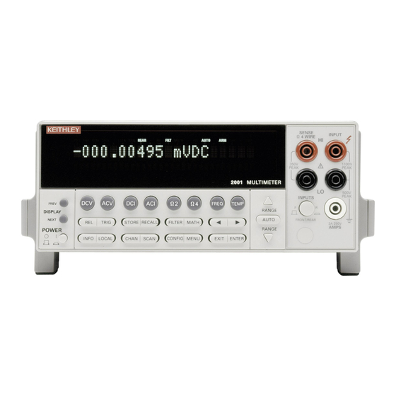
2.3 Overview of measurement process, page 6: Provides a 2.2.1 Front panel brief description of the measurement process. The front panel controls and connections of the Model 2001 2.4 Initial configuration, page 8: Reviews initial configu- are shown in Figure 2-1. - Page 16 NEXT: Moves to next multiple display of a function resistance measurements POWER INPUTS 0 = OFF Selects input connections on front or rear panels 1 = ON 10 CAL Enables calibration functions cáÖìêÉ=OJN Model 2001 front panel 2001-900-01 Rev. K / August 2010...
- Page 17 BNC CONNECTIONS LO (Chassis) SCANNER INPUT CONNECTIONS Optional Model 2001-SCAN Scanner Card installs in this slot INPUT HI and LO: Used for making DC volts, AC volts, and 2-wire resistance measurements. AMPS FUSE AMPS: Used in conjunction with INPUT LO to make DC Holds current input fuse (2A, 250V, fast blow, 520mm)
-
Page 18: Front Panel Display
Table 2-2. of multiple displays. In the multiple display mode, the Model 2001 can show the readings of up to three separate measurements. For example, in the DC voltage function, one of the multiple displays shows DC volts, AC ripple voltage, and ripple frequency: +00.00000 VDC... - Page 19 Readings of adjacent internal channels +00.00000 VDC CH02 (with Model 2001-SCAN option). CH01=+00.0000 V CH03=+00.0000 V NEXT PREV Note: Press the NEXT and PREV DISPLAY keys to scroll through the multiple displays (with wraparound). 2001-900-01 Rev. K/ August 2010...
-
Page 20: Overview Of Measurement Process
Message displays Menu summary While operating the Model 2001, the front panel display is also used for showing status and error messages. These messages are shown to inform you of parameter conflicts, CONFIG-DCV Press the CONFIG key, then the DCV trigger overruns, etc. -
Page 21: Idle
With one of the other scan sources selected (External, Manual, GPIB, Trigger Link, Timer, or When the Model 2001 is taken out of the idle state by Hold), the instrument waits until the appropriate event pressing TRIG (or sending the :INIT or :INIT:CONT ON occurs. -
Page 22: Initial Configuration
DC voltage are: •Measurement speed (integration time) Normal, 1 The Model 2001 can save from one to ten user setups in power line cycle. memory, depending on the installed memory option. You can •Digital filter ... - Page 23 (outer position for front jacks, inner position for rear). • Digital filter Advanced, 10 readings, 1% noise 2. Using the set of supplied test leads, connect the Model 2001 to a DC voltage source (e.g., a battery) as shown in tolerance, moving average, enabled. Figure 2-4.
- Page 24 ENTER. DCV DIGITAL FILTER AUTO AVERAGING ADVANCED 8. Press EXIT to return to the normal display. The reading AVERAGING-MODE should reflect the speed and resolution changes. (Changes will affect only the DCV function.) 2-10 2001-900-01 Rev. K / August 2010...
-
Page 25: Storing Dc Voltage Readings Example
Recall the readings 2.5.2 Storing DC voltage readings example To recall the stored readings, perform the following: This example assumes the Model 2001 is reset to its bench 1. Press RECALL to view the readings. The following defaults, as outlined in paragraph 2.4. - Page 26 2. A math operation slows post-processing time. 3. Select ON and press ENTER. (Certain instrument parameters are saved when burst is enabled, and are restored when burst is disabled. See paragraph 3.8.1 further details on burst mode.) 2-12 2001-900-01 Rev. K / August 2010...
-
Page 27: Ieee-488.2 And Scpi Basics
488.1) will work with the new standard. Simply connect the 5. Use the cursor and RANGE and keys to change Model 2001 to a computer that is equipped with an IEEE- the buffer size. Then press ENTER for the change to 488 interface. - Page 28 :TRIGger:SOURce? query command is used to request the computer. presently selected control source. After the query command is sent and the Model 2001 is addressed to talk, a message q~ÄäÉ=OJS Abbreviated common command summary *CLS Clear status Clears error queue, event registers, and IEEE-488 bus service request (SRQ) line.
-
Page 29: Syntax Rules
Table 2-7. Notice that they are hierarchical in nature and programming syntax for the Model 2001. For more complete begin with a root command. For example, to set autoranging information, see paragraph 4.9. on the DC voltage function, you would send the following command: 2001-900-01 Rev. - Page 30 “0” disables the function. Notice that the colon for the additional commands is not 4. Model 2001 This string parameter specifies the user included. Remember, when a colon (not preceded by a text message. Single or double quotes delimit the semicolon) is seen, the path pointer moves down to the next message.
-
Page 31: Programming Examples
The following programming examples are written in the 170 OUTPUT 716;“:trac:data?” Hewlett-Packard BASIC 4.0 programming language. The 180 ENTER 716;A$ programs assume that the Model 2001 is set to primary 190 PRINT A$ address 16. Line 100 Return Model 2001 to default configuration. - Page 32 170 WAIT 2 180 OUTPUT 716;”:trac:data?” 190 ENTER 716;A$ 200 PRINT A$ Line 100 Return Model 2001 to default configuration. Line 110 Change acquisition method to burst; put unit in idle. Line 120 Specify data elements (reading, reading number, units, and status).
-
Page 33: Front Panel Operation
2-wire and 4-wire resistance, frequency, and 1. The Model 2001 operates from a line voltage in the temperature) and typical test connections. range of 90-134V or 180-250V at a frequency of 50, 60, or 400Hz. -
Page 34: Line Fuse Replacement
“yy” is the year. If no calibration date is set, the display the cause of the trouble before replacing shows that it is due now. (See the Model 2001 Calibration the fuse. See the optional Model 2001 Manual to set the calibration due date and paragraph 3.12.3... -
Page 35: High Energy Circuit Safety Precautions
3. Error +512, Power-on state lost, may occur the first time the unit is powered-up after replacing the MEM2 memory option with MEM1. 3.2.4 High energy circuit safety precautions To optimize safety when measuring voltage in high energy distribution circuits, read and use the directions in the following warning. 2001-900-01 Rev. J / October 2009... -
Page 36: Power-On Default Conditions
3.2.6 Warm-up period The Model 2001 can be used within one minute after it is When making measurements in high energy circuits, use test turned on. However, the instrument should be turned on and leads that meet the following requirements: allowed to warm up for at least one hour before use to achieve rated accuracy. - Page 37 REN line true. • The top line can display readings up to 7H digits, along TALK: Shows that the Model 2001 is the active talker on the with units. It can also indicate the measurement type IEEE-488 bus.
-
Page 38: Multiple Displays
(except in-circuit current, which has a fixed 12A range), or resistance measurements. ARM: Turns on when the Model 2001 is taken out of the idle state (by the TRIG key or the :INIT or :INIT:CONT ON bus command). A measurement can only be performed with the Model 2001 out of the idle state. - Page 39 The “normal” bar graph, with a zero at the left end, is a graphical representation of a reading as a portion of a range. (See Figure 3-3.) The vertical lines displayed along the bar designate 0%, 25%, 50%, 75%, and 100% of full scale. Each full segment of the bar represents approximately 4% of the range limit. 2001-900-01 Rev. J / October 2009...
- Page 40 BARGRAPH:0 to 0040°C RANGE keys to enter a numeric value (0.01 - 99.99%). Press ENTER when done. The same percent- 3. Change the frequency range by highlighting one of the selections and pressing ENTER. For the temperature 2001-900-01 Rev. K/ August 2010...
-
Page 41: Information Messages
(0 - 9999°C). Press ENTER when 3.3.4 Status and error messages done. During Model 2001 operation and programming, you will Maximum and minimum encounter a number of front panel messages. Typical messages are either of status or error variety, as listed in... - Page 42 “Command Header Error” -440 “Query unterminated after indefinite -111 “Command Header Separator Error” response” -112 “Program mnemonic too long” -113 “Undefined header” SE = Status event EE = Error event -114 “Header suffix out of range” 3-10 2001-900-01 Rev. K/ August 2010...
-
Page 43: Menu Structures
3. Pressing the ENTER key selects an item and, if further definition is needed, moves down within the menu From the front panel of the Model 2001, you configure structure. Pressing the EXIT key backs up within a measurements through the use of menus. The menus are menu structure. -
Page 44: Functions
• Multiple displays Functions To access the configuration menus for the measurement The Model 2001 has much flexibility when configuring the functions, press the CONFIG key and then a function key measurement functions. This flexibility must be used (DCV, ACV, DCI, ACI, 2, 4, FREQ, TEMP). Rules for... -
Page 45: Dc And Ac Voltage
1. Connect the test leads to the INPUT HI and LO termi- procedure is as follows: nals of the Model 2001. Either the front or rear inputs can be used; place the INPUTS button in the appropriate 1. Connect the test leads to the INPUT HI and LO termi- position. - Page 46 Select 1 PLC (power line cycle, 16.67msec for 60Hz, 20msec for 50Hz and 400Hz). FAST Select 0.01 PLC. MEDIUM Select 0.1 PLC. HIACCURACY Select 10 PLC. SET-SPEED-EXACTLY Set integration time in PLC (0.01-10). SET-BY-RSLN Default to setting appropriate for resolution. 3-14 2001-900-01 Rev. K/ August 2010...
- Page 47 Program a simple average filter (1-100 readings) with a noise tolerance window (0-100% of range). AVERAGING-MODE Select moving average or repeating average mode. RESOLUTION Display resolution menu: AUTO Default to resolution appropriate for integration time. 3.5d, 4.5d, 5.5d, 6.5d, 7.5d Select a specific resolution. 2001-900-01 Rev. K/ August 2010 3-15...
- Page 48 (NPLC), where 1 PLC for 60Hz is 16.67msec and 1 PLC for 50Hz and 400Hz is 20msec. The optimum integration time setting for a given application depends on your measurement requirements. If speed is of 3-16 2001-900-01 Rev. K/ August 2010...
- Page 49 After selecting this menu item, cursor position indicates the present state (ON or OFF) of the analog filter. To change the state, place the cursor (using the keys) on the alternate selection and press ENTER. 2001-900-01 Rev. K/ August 2010 3-17...
- Page 50 2. For DCV peak spikes, low frequency RMS, and ACV peak measurements, the integration time setting is ignored. 3. For RMS and average measurements, if the resolution is AUTO and the integration time is SET-BY-RSLN, the res- olution will be 5.5 digits and the integration time 1.0 PLC. 3-18 2001-900-01 Rev. K/ August 2010...
- Page 51 With a user-programmable reference impedance, This parameter selects the displayed units for AC voltage the Model 2001 reads 0dBm when the voltage needed to measurements. You can program the ACV units parameter as dissipate 1mW through the reference impedance is applied.
- Page 52 4 digits (3.5d from SET ACV This parameter selects the measurement type for the ACV RESOLUTION menu) to 8 digits (7.5d), but the accuracy is function. The Model 2001 directly measures RMS, average, specified at 4 digits. In addition, the accuracy Specifications and peak AC voltages.
- Page 53 The displays for DC and AC voltage that show multiple functions are shown in Figures 3-9 and 3-10. The multiple display for crest factor, which is calculated from the peak and RMS values, is described here. 2001-900-01 Rev. K/ August 2010 3-21...
- Page 54 RESOLUTION = Fixed at 5 digits. AC-TYPE = Fixed on normal mode RMS. COUPLING = Fixed on AC coupling. INPUT TERMINALS = Fixed on VOLTAGE. A. DC voltage, AC voltage, and frequency functions cáÖìêÉ=PJV DC voltage multifunction multiple displays 3-22 2001-900-01 Rev. K/ August 2010...
- Page 55 UNITS = Fixed on volts. COUPLING = Fixed on AC+DC coupling. NOTE: The peak detector captures the maximum val- ue of the input signal. B. DC voltage and positive peak spikes functions cáÖìêÉ=PJV=EÅçåíáåìÉÇF DC voltage multifunction multiple displays 2001-900-01 Rev. K/ August 2010 3-23...
- Page 56 UNITS = Fixed on volts. COUPLING = Fixed on AC+DC coupling. NOTE: The peak detector captures the minimum val- ue of the input signal. C. DC voltage and negative peak spikes functions cáÖìêÉ=PJV=EÅçåíáåìÉÇF DC voltage multifunction multiple displays 3-24 2001-900-01 Rev. K/ August 2010...
- Page 57 NOTE: The peak detector captures the maximum val- NOTE: The peak detector captures the minimum val- ue of the input signal. ue of the input signal. D. DC voltage, positive and negative peak spikes functions cáÖìêÉ=PJV=EÅçåíáåìÉÇF DC voltage multifunction multiple displays 2001-900-01 Rev. K/ August 2010 3-25...
- Page 58 NOTE: Crest factor (up to 9.99) is calculated from an ACV peak mea- surement divided by the raw (without rel) ACV RMS measurement. A. AC RMS voltage, frequency, and crest factor cáÖìêÉ=PJNM AC voltage multifunction multiple displays 3-26 2001-900-01 Rev. K/ August 2010...
- Page 59 Therefore, to minimize AC interference, the circuit should be shielded with the shield connected to For the Model 2001, the additional error term for RMS the Model 2001 INPUT LO (particularly for low-level measurements caused by a high crest factor is specified up to sources).
-
Page 60: Dc And Ac Current
To minimize the drift caused by thermal emfs, use copper played reading. leads to connect the circuit to the Model 2001. A banana plug generates a few microvolts. A clean copper conductor such as #10 bus wire is ideal for this application. The leads to the 3.4.2... - Page 61 3.12.1), the basic procedure is as follows: 1. Connect the test leads to the AMPS and INPUT LO ter- minals of the Model 2001. Either the front or rear inputs can be used; place the INPUTS button in the appropriate position.
- Page 62 The following paragraphs detail how to change the Model the fuse carrier out of the holder. 2001 from its bench reset conditions for DC and AC current 3. Remove the fuse and replace it with the same type (2A, measurements. The configuration menus are summarized in 250V, fast blow, 5 ...
- Page 63 2. For DC in-circuit current, the integration time setting is ignored. 3. For AC current, if the integration time is SET-BY-RSLN and the resolution is AUTO, the integration time will be 1.0 PLC and the resolution 5.5 digits. 2001-900-01 Rev. K/ August 2010 3-31...
- Page 64 MEASUREMENT-MODE and press ENTER. The This option selects the DC current measurement mode, following menu is shown: either normal or in-circuit measurements. It is programmed DCI MEASUREMENT MODE as follows: NORMAL IN-CIRCUIT 3-32 2001-900-01 Rev. K/ August 2010...
- Page 65 The current in a low resistance conductor (e.g., a printed MEAS1 IN-CKT MEAS2 IN-CKT SOURCE circuit trace) can be measured without breaking the current path. The Model 2001 can do this with a pair of Kelvin test -V ...
- Page 66 2. Highlight the desired measurement type and press EN- 2. Connect a set of Kelvin test probes, such as Keithley TER. Model 5805 or 5806, to the Model 2001 INPUT HI and LO terminals and SENSE HI and LO terminals. With this parameter selected, the instrument performs 3.
-
Page 67: Two And Four-Wire Resistance
5. Connect the test leads to the resistance as shown in 1. Connect test leads to the INPUT HI and LO terminals of Figure 3-14. the Model 2001. Either the front or rear inputs can be used; place the INPUTS button in the appropriate position. 2. Select the 2 function. - Page 68 1. Connect test leads to the INPUT HI and LO and SENSE establish a baseline for subsequent measurements on that 4 WIRE HI and LO terminals of the Model 2001. Rec- range. The 20 and 200 resistance ranges require zero ommended Kelvin test probes include the Keithley correction to correct for thermal offsets.
- Page 69 Resistance configuration The following paragraphs detail how to change the Model Shielding 2001 from its bench reset conditions for 2-wire and 4-wire It helps to shield resistance greater than 100k to achieve a resistance measurements. The configuration menus are stable reading. Place the resistance in a shielded enclosure...
- Page 70 3.9. Only the specifics for 2- and 4-wire resistance are covered here. The AUTO parameter for a digital filter optimizes its use for the present measurement function. The defaults for automatic filtering of 2 and 4 are listed in Table 3-19. 3-38 2001-900-01 Rev. K/ August 2010...
- Page 71 The available resolution on all resistance functions and types voltages in the measurement circuit, but it also compensates is 3.5 digits to 7.5 digits. If the 2 or 4 resolution is AUTO, for thermal voltages generated within the Model 2001. In refer to Table 3-20...
-
Page 72: Frequency
3.12.1), the basic procedure is as follows: 1. Connect the test leads to the INPUT HI and LO termi- nals of the Model 2001. Either the front or rear inputs can be used; place the INPUTS button in the appropriate position. - Page 73 The following paragraphs detail how to change the Model returns the trigger level to 0V or 0mA. After pressing one of 2001 from its bench reset conditions for frequency the range keys, the present trigger level is momentarily measurements. The configuration menu is summarized in displayed.
- Page 74 This parameter selects the input coupling for the frequency function. When AC coupling is selected, a DC blocking capacitor is placed in series with the input. This removes the DC component of the input signal. 3-42 2001-900-01 Rev. K/ August 2010...
-
Page 75: Temperature
PT385 4-wire RTD (the default sensor) is as follows: 1. Connect the RTD sensor to the Model 2001 as shown in Figure 3-17. You can use banana plugs (with the front or rear inputs), or the optional Model 8680 RTD Probe 2001-900-01 Rev. - Page 76 FILTER MATH 2A 250V POWER AMPS RANGE INFO LOCAL CHAN SCAN CONFIG MENU EXIT ENTER Input LO Sense Ω4-wire LO Input HI Input LO C. Connections to Terminal Block cáÖìêÉ=PJNT 4-wire RTD temperature measurements 3-44 2001-900-01 Rev. K/ August 2010...
- Page 77 B. Connections to Terminal Block WARNING : To avoid a shock hazard and possible instrument damage, do not use the Model 8680 RTD Probe Adapter to measure voltages exceeding 30V RMS, 42.4V peak. cáÖìêÉ=PJNV 2-wire RTD temperature measurements 2001-900-01 Rev. K/ August 2010 3-45...
- Page 78 Front Panel Operation MODEL 7402 Model 7057A Thermocouple Scanner Card Note: The thermocouple card must be inserted into a Keithley Model 705 or 706 Scanner or Model 7001 Switch System. CABLE CLAMP OUTPUT HI LO CH 9 CH 8 Model 2001...
- Page 79 (Model 7057A or Model 7402). This parameter is used to select the temperature sensor. If You can select the temperature sensor as follows: using a 4- or 3-wire RTD sensor, choose 4-WIRE-RTD. If 2001-900-01 Rev. K/ August 2010 3-47...
- Page 80 RTD calibration, refer to NIST Technical Note 1265 "Guidelines For Realizing the International Temperature Scale of 1990". In each subrange, the calibration constants required for that range are listed. 3-48 2001-900-01 Rev. K/ August 2010...
- Page 81 0°C resistance value and the following coefficients: constants and the temperature range supported. In all cases • Set the Model 2001 A4 coefficient to the RTD except subranges #4 and #7, translation of the supplied certificate A2 value.
- Page 82 The defaults for UNITS automatic filtering of temperature are as follows: This parameter selects the displayed units for temperature Averaging measurements. You can program the temperature units State Type Readings Mode parameter as follows: Averaging Moving 3-50 2001-900-01 Rev. K/ August 2010...
-
Page 83: Range
3.5.1 Display resolution Temperature auto resolution The display resolution of a Model 2001 reading depends on Resolution the selected range and the resolution setting. The default and Sensor Degree Digits maximum display resolutions for every range on each function are included in the Specifications. -
Page 84: Autoranging
Autoranging increase the maximum allowable input for that range. For speeds are covered in the Specifications. example, on the 2mA range, the Model 2001 still overflows for a 2.1mA input. Note that up-ranging occurs at 105% of range, while down- q~ÄäÉ=PJOT... -
Page 85: Enabling Rel
Note that a bench or GPIB reset clears any stored rel values Model 2001 triggers are set up in the CONFIGURE and disables rel for all functions. TRIGGER menu. The menu structure is shown and... - Page 86 INFINITE Continuously re-arm meter. ENTER-ARM-COUNT User defined count value (1-99999). CONTROL Select trigger control mode: SOURCE Enable Source Bypass. ACCEPTOR Disable Source Bypass. HALT Use to halt triggers. Press TRIG key to resume triggering. 3-54 2001-900-01 Rev. K/ August 2010...
- Page 87 Source Output Detection Trigger Immediate External Manual GPIB Triglink Timer Hold Measure Delay Delay Device Action * Take bypass path the first time a layer is entered cáÖìêÉ=PJOO Trigger model (front panel operation) 2001-900-01 Rev. J / October 2009 3-55...
- Page 88 Model 2001 or a manual trigger (i.e., pressing TRIG key) occurs. The external From the front panel there are four ways to put the or manual trigger is not used (ignored).
- Page 89 “trigger ignored” message will be appropriate event occurs: displayed if an external trigger is sent to the Model 2001 or a manual trigger (i.e., • With the External source selected, the instrument waits pressing TRIG key) occurs. The external for an input trigger via EXTERNAL TRIGGER on the or manual trigger is not used (ignored).
-
Page 90: Configuring The Measure Layer
Each trigger stimulus applied paragraph 3.7.7 for details on using to the Model 2001 performs a device action, as defined by the Trigger Link. the trigger model. In addition to a measurement, this may include range changing, filtering, calculations, data storing, After the Device Action and an output trigger occurs, the in- scanning, and other operations. - Page 91 *TRG), it performs a device action, as defined by the trigger model. In addition to a measurement, this may include range 2. To select a trigger input line for the Model 2001, place changing, filtering, calculations, data storing, scanning, and the cursor on the desired line number and press ENTER.
- Page 92 Front Panel Operation 2. To select a trigger line for the Model 2001, place the cur- DELAY sor on the desired line number and press ENTER. The This delay is used to hold up operation in the measure layer. instrument returns to the SELECT MEASURE SRC After the measure event occurs, the instrument waits until menu.
-
Page 93: Configuring The Scan Layer
CONTROL and pressing ENTER. The to control the scan source. A trigger stimulus applied to the following menu is displayed: Model 2001 passes operation into the measure layer. The external trigger is applied to the rear panel “EXTERNAL TRIGGER CONTROL TRIGGER”... - Page 94 TER when done to return to the SELECT SCAN SOURCE menu. To select a trigger input line for the Model 2001, place the cursor on the desired line number and press ENTER. The HOLD: When HOLD is selected, the scan source is following message is displayed: suppressed.
-
Page 95: Configuring The Arm Layer
ARM and press ENTER to access the following menu: determines the number of times operation returns to the scan layer. You can program the Model 2001 to scan up to 99999 SETUP ARM LAYER times. Perform the following steps to enter the scan count: SOURCE COUNT CONTROL 1. - Page 96 Front Panel Operation NOTE To select a trigger input line for the Model 2001, place the cursor on the desired line number and press ENTER. The The front panel TRIG key is active when following message is displayed: EXTERNAL, GPIB, or TRIGLINK is se- lected.
-
Page 97: Halting Triggers
Press TRIG key to resume. 2µs Minimum 3.7.6 External triggering cáÖìêÉ=PJOQ The Model 2001 has BNC connections on the rear panel for External triggering and asynchronous trigger link input external triggering (see Figure 3-23). The EXTERNAL pulse specifications TRIGGER INPUT jack allows the Model 2001 to be triggered by other instruments. - Page 98 See paragraph 3.7.2 for details on programming the measure layer. The Model 2001 can also output a completion pulse while in the scan and/or arm layers of operation. Figure 3-22 shows where these triggers occur in the trigger model. If the scan...
- Page 99 Card 1 7011 MUX Card cáÖìêÉ=PJOS DUT test system Channel External Ready Trigger External Meter Trigger Complete Input Output 7001 Switch System 2001 Multimeter 7051-2 BNC to BNC Cables (2) cáÖìêÉ=PJOT External trigger connectors 2001-900-01 Rev. K/ August 2010 3-67...
-
Page 100: Trigger Link
Measure trigger control = Acceptor* * Indicates that the setting is the BENCH RESET (and The data store capability of the Model 2001 could be used to factory) default condition. store the measurements as they occur. Just press the STORE... - Page 101 Scan and arm layers as selected in the measure layer. In general, Trigger Link input triggers to the Model 2001 are Asynchronous Trigger Link example #1 used to control the measure operation. For the Model 2001 to...
- Page 102 Input LO 2001 Multimeter Card 1 7011 MUX Card cáÖìêÉ=PJOV DUT test system IN OUT Trigger Link Trigger Link 7001 Switch System 2001 Multimeter Trigger Link Cable (8501) cáÖìêÉ=PJPM Trigger Link connections (asynchronous example #1) 3-70 2001-900-01 Rev. K/ August 2010...
- Page 103 * Indicates that the setting is the BENCH RESET (and pressing the STEP key. factory) default condition. To run the test and store the readings in the Model 2001, Model 7001: press STORE on the multimeter, enter the desired number of readings (ten), and press ENTER.
- Page 104 B for a trigger. Instead, it bypasses “Wait for Trigger Link Trigger” and closes the first channel The trigger applied to the Model 7001 from the Model 2001 closes the next channel in the scan. This triggers the 3-72 2001-900-01 Rev.
- Page 105 Keithley Model 706 Scanner can until all ten channels are scanned and measured. be connected to the Trigger Link of the Model 2001 using the adapter. With this adapter, a Model 706 could be substituted External Triggering and Trigger Link for the Model 7001 in the previous example (Asynchronous Trigger Link example #1).
- Page 106 For this example, the Model 230 is programmed for External Scan layer: Triggering and is set to source the first voltage level. The Scan source = Immediate* Models 2001 and 7001 are configured as follows: Scan count = Infinite* Scan trigger control = Acceptor* Model 2001:...
- Page 107 After the voltage level is set, the Model 230 outputs a trigger pulse (point G). To run the test and store the readings in the Model 2001, press STORE on the multimeter, enter the desired number of The trigger pulse applied to the Model 7001 from the Model readings (20), and press ENTER.
- Page 108 3-36). The advantage of this single line trigger is that In the Semi-synchronous Trigger Link mode, all triggering as long as one of the instruments in the system holds the line (input and output) is controlled by a single line. When the 3-76 2001-900-01 Rev. K/ August 2010...
- Page 109 Model 2001 to make a measurement and subsequently pull the trigger line back down to close the next channels. This process continues until all channels are For example, assume that a Model 2001 is connected to two scanned and measured. Model 7001 Switch Systems for semi-synchronous...
- Page 110 Model 7001: To run the test and store the readings in the Model 2001, press STORE on the multimeter, enter the desired number of Idle state: readings (ten), and press ENTER. The Model 2001 waits...
-
Page 111: Buffer
Operation mode for semi-synchronous Trigger Link example Buffer q~ÄäÉ=PJPM Reading storage options The Model 2001 has a buffer to store reading data. It can acquire readings at two different rates (normal and burst Data group modes). The maximum possible number of stored readings... - Page 112 The burst data acquisition mode maximizes the reading rate when burst mode starts. of the Model 2001. Burst mode consists of two distinct phases: • Set the trigger event source in the measure layer to immediate, external, trigger link, or timer.
-
Page 113: Burst Mode
BURST-MODE DATA-GROUP CONTROL The acquisition phase of burst mode can be aborted by CLEAR-ALL COUNT FEED pressing the EXIT key. Then the Model 2001 starts post- processing on that portion of the reading buffer. 3. Use the cursor keys ( ) to highlight BURST- MODE and press ENTER. -
Page 114: Configuring Data Storage
• To specify the number of readings to store. 2. Use the cursor keys ( ) to highlight the appro- priate item and press ENTER to select it. • To specify the source of readings to be stored. 3-82 2001-900-01 Rev. K/ August 2010... - Page 115 The first reading after the trigger is reading zero. Pretrigger AFTER-CALC BEFORE-CALC NONE readings have reading numbers and time-stamps with a minus sign; post-trigger readings have reading numbers and time-stamps with a plus sign. 2001-900-01 Rev. K/ August 2010 3-83...
-
Page 116: Storing And Recalling Readings
(* off) RECALL Rdg#-00050 @Time=-004.999990 sec Rdg#+00000 @Time=+000.000000 sec Rdg#+00049 @Time=+004.899996 sec EXIT (normal reading display) Note: A manual trigger is used as an example. Other pretrigger events include GPIB, trigger link, and external. 3-84 2001-900-01 Rev. K/ August 2010... -
Page 117: Buffer Multiple Displays
AVG=+1.6345e+00 (e.g., when scanning different functions). The equation used to calculate the mean is: NOTE The Model 2001 uses IEEE-754 floating point format for math calculations. -------------- - where: x is a stored reading, and The last display in this series allows you to dump the buff- n is the number of stored readings. -
Page 118: Filters
3.9.7. 3.9.1 Digital filter types The Model 2001 has two types of digital filters: averaging and advanced. Both types are a simple average of one to 100 reading conversions. The difference between them is the user-programmable noise “window” of the advanced filter. - Page 119 Readings = 5 Mode = repeating Reading Reading Conversions: Type = advanced Readings = 5 Mode = repeating Noise level =1% of range Reading Reading A. Averaging and advanced filter types cáÖìêÉ=PJQM Digital filter 2001-900-01 Rev. J / October 2009 3-87...
-
Page 120: Response Time (Digital Filter)
For those measurement functions with a filter, one of the possible selections is automatic filtering. Depending on the measurement function and type, the AUTO selection may disable filtering. Auto filtering is summarized in Table 3-36. 3-88 2001-900-01 Rev. K/ August 2010... - Page 121 Default to filter appropriate for measurement function and type. Averaging Program simple average filter (1-100 readings). Advanced Program simple average filter (1-100 readings), with a noise tolerance window (0-100% of range). Averaging-mode Select moving average or repeating average mode. 2001-900-01 Rev. K/ August 2010 3-89...
-
Page 122: Enabling/Disabling The Filter
With the FILT annunciator on, the vanced filter type. filtering action depends on the selections chosen in the FILTER menu for the present function. With the FILT 3-90 2001-900-01 Rev. K/ August 2010... -
Page 123: Analog Filter
Analog filter the analog filter is enabled. The Model 2001 has an analog filter for use with the DCV function. This filter reduces the number of overflow errors caused by noise seen on the input signal. The analog filter is most effective when measuring voltages greater than 2 Vp-p frequencies ranging from 10kHz to 1MHz. -
Page 124: Math
Note that once enabled for a function, the mX+b, percentage, and percent deviation calculations are in effect across 3.10 Math function changes. Model 2001 math operations are divided into four NOTE categories: The Model 2001 uses IEEE-754 floating • Math performed on single readings (mX+b and point format for math calculations. -
Page 125: Percent
20k range will be displayed as 10.00000. If the number is CONFIGURE MATH menu. too large for the allowed number of leading zeroes (for example 10 on the 2k range), the display will switch to 7- 1/2 digit scientific notation. 2001-900-01 Rev. K/ August 2010 3-93... -
Page 126: Enabling Math
This menu item selects the percent deviation calculation and returns the display to the normal measurement state. The Model 2001 can be used with an internal scanner card (Model 2001-SCAN) or with external scanner cards installed in switching mainframes such as the Models 706 and 7001. -
Page 127: Front Panel Scanner Controls
More detailed descriptions of these menu items are presented in the In order to synchronize Model 2001 measurements with ex- following paragraphs. See paragraph 3.3... -
Page 128: Using Config-Chan To Configure Channels
ENTER. Once TMP function: Similarly, the TMP selection is valid only for 4W is selected on channels 1 to 5, changing the assignment channels 1-5 if the temperature sensor is a 4-wire RTD type. 3-96 2001-900-01 Rev. K/ August 2010... -
Page 129: Using Config-Scan To Configure Scanning
Model 2001 Multimeter. When the EXTERNAL-INPUTS menu item is selected, the instrument NOTE will prompt you to enter the number of channels being used:... - Page 130 When this selection is chosen, the RATIO MEASURE CHAN Model 2001 will change to the function specified for the first CH1 2 3 4 5 6 7 8 9 10 channel and then close the channel and take a reading. When...
-
Page 131: Using Scan To Configure Scan Parameters
To use this feature, first close a channel by using the CLOSE-CHANNEL option accessible with the CHAN key. Use to increment channels, or use to decrement channels. Hold down either key to continuously scan through channels manually. 2001-900-01 Rev. K/ August 2010 3-99... - Page 132 XXXX scans of XX channels or > < press EXIT to abort. EXIT DISABLE EXT SCANNER (For an external list only) Set CHAN SPACING to MANUAL > < Press ENTER to continue. cáÖìêÉ=PJQO SCAN key menu structure 3-100 2001-900-01 Rev. K/ August 2010...
-
Page 133: Scanner Operation Examples
CHANNEL SELECTION Internal channels are scanned by configuring scan channels CLOSE-CHANNEL OPEN-ALL-CHANNELS and programming the Model 2001 to perform a scan. The following steps demonstrate the basic procedures for 2. Select CLOSE-CHANNEL, then press ENTER. The performing basic scanning using the internal scanner card. - Page 134 Step 2: Select internal scan list INTERNAL EXTERNAL RATIO DELTA Use CONFIG-SCAN to select the internal scan list as follows: 2. Select RATIO, then press ENTER. The Model 2001 will display the following: 1. Press CONFIG-SCAN. The Model 2001 will display CONFIGURE RATIO...
- Page 135 Using the scanner with the data storage buffer Step 1: Connect RTD probes The Model 2001 internal data storage buffer can be used to Connect RTD probes to the scanner using the basic store readings taken while using the scanner. The following resistance connections outlined in the scanner card manual.
- Page 136 COMPLETE menu. functions and channels. External scanning 4. Press EXIT to return to normal display. Follow the general steps below to set Model 2001 modes for Step 2: Configure scan external scanning. 1. From normal display, press CONFIG-SCAN. The in-...
-
Page 137: Menu
MENU key. The main menu options are shown as follows: MAIN MENU SAVESETUP GPIB CALIBRATION TEST LIMITS STATUS-MSG GENERAL Some general rules to navigate the menu levels are given in paragraph 3.3. 2001-900-01 Rev. K/ August 2010 3-105... - Page 138 Setup menu: SAVE Save setup at a memory location (up to 1, 5, or 10). RESTORE Return 2001 to setup stored at a memory location (up to 1, 5, or 10). POWERON Power-on Menu: BENCH Power on to bench default setup conditions.
-
Page 139: Savesetup
Use this menu item to return the instrument to a setup that specific memory location. Depending on the memory option, was previously stored in memory. Depending on the memory you can store up to one (STD), five (MEM1), or ten (MEM2) 2001-900-01 Rev. K/ August 2010 3-107... - Page 140 To select a user setup, place the cursor on USER-SETUP-NUMBER and press ENTER. The following message is displayed for the Model 2001/MEM1: PWRON DFLT#0 (4 max) 3-108...
- Page 141 75 Autozero On (Normal) On (Normal) Buffer: Burst mode No effect No effect Control No effect No effect Count No effect No effect Data group No effect No effect Feed No effect No effect 2001-900-01 Rev. K/ August 2010 3-109...
- Page 142 No effect No effect Output sense No effect No effect Frequency: Coupling Maximum signal level: Function Voltage Voltage Voltage level Current level Relative Value Resolution Auto (5d) Auto (5d) Terminals Voltage Voltage Trigger level Function 3-110 2001-900-01 Rev. K/ August 2010...
- Page 143 Averaging Readings Advanced Readings Noise tolerance level Filter mode Moving Repeat Offset compensation Range Auto Auto Maximum autorange 1G 1G Relative Value Resolution Auto (6.5d) Auto (6.5d) Speed Normal (1 PLC) Normal (1 PLC) 2001-900-01 Rev. K/ August 2010 3-111...
- Page 144 External list No channels No channels Function DC voltage DC voltage Scan operation None None Ratio: Reference channel Measure channel Function DC voltage DC voltage Delta: Reference channel Measure channel Function DC voltage DC voltage 3-112 2001-900-01 Rev. K/ August 2010...
- Page 145 Infinite Control Acceptor Acceptor measure layer: Source Immediate Immediate Asynchronous Triglink mode Asynchronous Triglink input Line 2 Line 2 Triglink output Line 1 Line 1 Timer 0.1sec 0.1sec Delay Count Infinite Control Acceptor Acceptor 2001-900-01 Rev. K/ August 2010 3-113...
-
Page 146: Gpib
READING=y UNITS=y READING#=y TALK-ONLY CHAN#=y TIMESTAMP=y STATUS=y In the talk-only mode, the Model 2001 ignores commands where a “y” designates “yes”, which is sent, and an “n” from the bus and merely outputs data, as requested by the designates “no”, which is not sent. To retain the displayed printer. -
Page 147: Calibration
MSB=0 EAV=0 QSB=0 MAV=0 ESB=0 MSS=0 OSB=0 To perform an AC-only calibration, follow these steps: 1. The Model 2001 must be allowed to warm up for at least When finished viewing the status byte, press either ENTER one hour before calibration. -
Page 148: Test
LOW1, HIGH1, LOW2, HIGH2. If all late problems with the Model 2001. Information on using tests pass, another programmable pattern is set. (Also see these test procedures is included in the optional Model 2001 DIGITAL I/O in paragraph 3.12.7.) - Page 149 3-44. DIGOUT1=OFF 2=OFF 3=OFF 4=OFF Note that the Model 2001 does not check the validity of the With this menu, you select the action taken if low limit #1 is high and low limit values when you enter them. If low limit the first limit to be exceeded.
- Page 150 • Values less than 90 (outside -10% tolerance). • Values greater than 110 (outside +10% tolerance). • Values between 90 and 99 (meets -10% tolerance). • Values between 101 and 110 (meets +10% tolerance). 3-118 2001-900-01 Rev. K/ August 2010...
-
Page 151: Status-Msg
Then the status message enable/disable menu is shown: Overview STATUS MESSAGES The Model 2001’s Digital I/O port is a 9-pin “D” sub- OFF ON miniature connector located on the rear panel. The port’s location and pin designations are shown in Figure 3-46. - Page 152 (+5V) or low (0V) and will sink up to 100mA. A TTL high (voltage range from +5V to +30V applied through the device on the Model 2001’s digital input is read as “ON”. The four being driven). Refer to Figure 3-46...
- Page 153 (transistor switch is open). This interrupts with the device. When using the Model 2001’s collector current flow through the external device. Most applications outputs to turn on externally powered devices, set the use active-low (ON=0V) OUTPUT-SENSE.
- Page 154 To use the digital outputs as logic inputs to active TTL, Low- NOTE power TTL, or CMOS inputs: If any LIMITS control is enabled 1. Connect the Model 2001 digital outputs to the logic in- (LOLIM1 or 2, HILIM1 or 2—High, Low, puts. or Pass), the OUTPUT-STATE menu does 2.
- Page 155 1. Place the cursor on the appropriate line and press EN- Using the Model 2001 with auto zero disabled has two main TER. A message indicating the sense of the selected line advantages: is displayed.
- Page 156 SET AUTOZERO readings. DISABLE NORMAL SYNCHRONOUS The cursor position indicates the present auto zero mode. To retain the presently selected sense, press ENTER or EXIT. The display returns to the SET AUTOZERO menu. 3-124 2001-900-01 Rev. K/ August 2010...
- Page 157 Power Line Frequency 3 PLC A/D Conversion A/D Conversion A/D Conversion #1 starts #2 starts #3 starts Note: A/D conversions assume an integration time of ≤ 1 PLC (Power Line Cycle) cáÖìêÉ=PJQV Line cycle synchronization 2001-900-01 Rev. K/ August 2010 3-125...
- Page 158 Front Panel Operation This page intentionally left blank. This page left blank intentionally. 3-126 2001-900-01 Rev. J / October 2009...
-
Page 159: Ieee-488 Reference
Covers the command group that can be used to control the This section contains reference information on programming measurement process. the Model 2001 over the IEEE-488 bus and is organized as Covers the SCPI commands used by the Model 2001. follows: 4.2 IEEE-488 bus connections, page 1: Explains instrument... - Page 160 Earlier versions had different screws, which were Connect the Model 2001 to the IEEE-488 bus as follows: silver colored. Do not attempt to use these type of connectors on the instrument, which is designed for metric threads.
-
Page 161: Primary Address Selection
DIO4 Data Primary address selection EOI (24)* Management Handshake The Model 2001 must receive a listen command before re- NRFD Handshake sponding to addressed commands. Similarly, the unit must NDAC Handshake receive a talk command before transmitting data. The Model... -
Page 162: Controller Programming
This language was chosen because of its versatility in con- that are part of IEEE-488 operation, including messages, sta- trolling the IEEE-488 bus. This section covers those state- ments that are essential to Model 2001 operation. tus indicators, and the LOCAL key. 4.5.1... -
Page 163: Local Key
Each bit in the register (except bit B1 which is not This indicator is on when the Model 2001 is in the used by the Model 2001) represents a standard event. - Page 164 Reading this register using the *ESE? command does not clear the register. The following list summarizes all opera- tions that will clear the Standard Event Status Enable Regis- ter: 1. Cycling power. 2. *ESE 0 2001-900-01 Rev. K / August 2010...
- Page 165 IEEE-488 Reference cáÖìêÉ=QJR Model 2001 status register structure 2001-900-01 Rev. K/ August 2010...
-
Page 166: Operation Event Status
1 to 0. rent operating conditions of the Model 2001. For example, while a calculation is being performed, bit B9 (Calc) of this register will be set. At the completion of the calculation, bit B9 will clear. - Page 167 1. Cycling power. command. 2. Sending the :STATus:PRESet command. This register is pro- 3. Sending the :STATus:OPERation:PTR 65535 and grammed by the user and serves as a mask for the Operation :STATus:OPERation:NTR 0 commands. 2001-900-01 Rev. K/ August 2010...
-
Page 168: Arm Event Status
4.7. 3. Sending the :STATus:OPERation:ARM:PTR 65535 and :STATus:OPERation:ARM:NTR 0 commands. The various registers used for arm event status are described as follows. Note that these registers are controlled by the 4-10 2001-900-01 Rev. K / August 2010... - Page 169 Enable Register (B15) (B14 - B3) (B2) (B1) (B0) Lay1 = Layer 1 (Set bit indicates that 2001 is & = Logical AND in arm layer 1). = Logical OR Lay2 = Layer 2 (Set bit indicates that 2001 is = Positive Transition Register in arm layer 2).
-
Page 170: Sequence Event Status
Operation Event Register: structured. 1. Cycling power. Two bits of this register set are used by the Model 2001 to re- 2. Sending the *CLS common command. port sequence events. Bit B1 (In arm layer 1) is set when in- 3. -
Page 171: Trigger Event Status
2. Sending the *CLS common command. Bit B1 (Seq1) of the register set is used for the trigger event 3. Sending the :STATus:OPERation:ARM:SEQuence? (In trigger layer of Sequence 1). In general, Bit B1 sets when query command. 2001-900-01 Rev. K/ August 2010 4-13... - Page 172 Trigger Event Transition Filter The transition filter is the instrument is in (or has exited) the measure layer of op- eration. An explanation of the Model 2001 operation process made up of two 16-bit registers that are programmed by the...
-
Page 173: Measurement Event Status
Operation Condition Register. Conversely, when unmasked, current operating conditions of the Model 2001. For exam- a set bit (B1) in the Trigger Event Register will set bit B5 of ple, when the trace buffer becomes full, bit B9 (BFL) of this the Operation Condition Register. - Page 174 The following operations will set (1) all the bits of the PTR in the Measurement Condition Register changes from 0 to 1. register and clear (0) all the bits of the NTR register: Conversely, when programmed for a negative transition, the 4-16 2001-900-01 Rev. K / August 2010...
-
Page 175: Questionable Event Status
“0” output of the AND gate is applied to the input of :STATus:QUEStionable commands :STATus the OR gate and thus, will not set the MSB bit in the Status subsystem (see paragraph 4.21). Byte Register. 2001-900-01 Rev. K/ August 2010 4-17... - Page 176 1 to 0. current operating conditions of the Model 2001. For exam- ple, when a calibration summary event occurs, bit B8 (Cal) The individual bits of the transition filter registers can be set will set.
-
Page 177: Queues
4.6.8 Queues :STATus:QUEStionable:EVENt? The Model 2001 uses two queues; the Output Queue and the Reading this register using the above SCPI command clears Error Queue. The queues are first-in first-out (FIFO) the register. The following list summarizes all operations registers. -
Page 178: Status Byte And Service Request (Srq)
Status byte and service request (SRQ) read by sending either of the following SCPI query com- Service request is controlled by two 8-bit registers; the Status mands and then addressing the Model 2001 to talk: Byte Register and the Service Request Enable Register. The :SYSTem:ERRor? - Page 179 Typically, service requests (SRQs) are man- aged by the serial poll sequence of the Model 2001. If an Service Request Enable Register This register is pro- SRQ does not occur, bit B6 (RQS) of the Status Byte Regis-...
-
Page 180: Trigger Model (Ieee-488 Operation)
Trigger Model (IEEE-488 operation) The following information describes the operation process of the Model 2001 over the IEEE-488 bus. The flowchart in cáÖìêÉ=QJNQ=, which summarizes operation over the bus, is called the Trigger Model. It is called the Trigger Model be-... -
Page 181: Scan Layer
:TRIGger:SIGNal (Measure Layer) Measure Event Source Output Detection Trigger :TRIGger:SOURce IMMediate :TRIGger:SOURce MANual :TRIGger:SOURce BUS :TRIGger:SOURce TIMer :TRIGger:SOURce EXTernal :TRIGger:SOURce TLINk :TRIGger:SOURce HOLD :TRIGger:DELay <num> Delay Device Action cáÖìêÉ=QJNQ Trigger Model (IEEE-488 bus operation) 2001-900-01 Rev. K/ August 2010 4-23... - Page 182 MANual), the instrument will wait until the front panel operation will loop around the arm control source. It is TRIG key is pressed. Note that the Model 2001 must be tak- used when you do not wish to wait for a programmed...
- Page 183 Output Trigger in this layer is disabled when the Source until the front panel TRIG key is pressed. Note that the Bypass is disabled (:ARM:TCONfigure:DIRection Model 2001 must be taken out of remote (press LOCAL key ACCeptor). or send LOCAL 716 over bus) before it will respond to the 3.
-
Page 184: General Bus Commands
:SOURce MANual), the instrument will wait until the front control source is selected). panel TRIG key is pressed. Note that the Model 2001 must 3. Each time the :TRIGger:SIGNal command is sent, be taken out of remote (press LOCAL key or send LOCAL operation will loop around the measure control source. -
Page 185: Ren (Remote Enable)
The IFC command is sent by the controller to place the Mod- REMOTE el 2001 in the local, talker, and listener idle states. The unit responds to the IFC command by cancelling front panel LOCAL LOCKOUT TALK or LISTEN lights, if the instrument was previously placed in one of those states. -
Page 186: Gtl (Go To Local) And Local
4.8.8 SPE, SPD (serial polling) instrument settings and stored data. The serial polling sequence is used to obtain the Model 2001 Programming example Use the following statement to serial poll byte. The serial poll byte contains important infor- perform a DCL:... - Page 187 PRINT “SPOLL BYTE =”;S After the first statement, the controller conducts the serial polling sequence. After the second statement is executed, the decimal value of the serial poll byte is displayed on the con- troller CRT. 2001-900-01 Rev. K/ August 2010 4-29...
- Page 188 IEEE-488 Reference This page intentionally left blank. 4-30 2001-900-01 Rev. J / October 2009...
-
Page 189: Programming Syntax
Explicit: This is an example of two explicit parameters to choose from; AC or DC. Example: :CURRent:AC:COUPling Select AC coupling <name> Name parameter: Select a parameter name from a listed group. Example: <name> = NEVer = NEXt = ALWays = PRETrigger 2001-900-01 Rev. K / August 2010 4-31... - Page 190 3. Case sensitivity: Common commands and SCPI commands are not case sensitive. You can use upper or lower case, and any case combination. Examples: *RST = *rst :SCAN? = :scan? :SYSTem:PRESet = :system:preset 4-32 2001-900-01 Rev. J / October 2009...
- Page 191 The brackets ([]) indicate that :EVENt is optional. Thus, either of the following two com- mand program messages are valid: :STATus:OPERation:EVENt?= :STATus:OPERation? Notice that when using the optional word or character, the brackets ([]) are not included in the program message. 2001-900-01 Rev. K / August 2010 4-33...
-
Page 192: Program Messages
If a colon were included, the path pointer would reset to the root level and expect a root command. Since neither :ptr nor :ntr are root commands, an error would occur. Command path rules: 4-34 2001-900-01 Rev. J / October 2009... -
Page 193: Response Messages
1. Sending a response message: After sending a query command, the response message is placed in the Output Queue. When the Model 2001 is then addressed to talk, the response message is sent from the Output Queue to the computer. The following example in HP BASIC 4.0 demonstrates this process: OUTPUT 716;... -
Page 194: Message Exchange Protocol
(see Multiple command messages), the multiple response message for all the queries will be sent to the computer when the Model 2001 is addressed to talk. The responses are sent in the order that the query commands were sent and will be separated by semicolons (;). Items within the same query are separated by commas (,). -
Page 195: Common Commands
This command issues a bus trigger which has the same effect as group execute trigger (GET) command. *TST? Self-test query When this query is sent, the Model 2001 will perform a checksum test on ROM and return the results. *WAI Wait-to-continue command Wait until all previous commands are executed. -
Page 196: Cls - Clear Status
This register is used as a mask for the Standard Event Status Register. When a standard event is masked, the occurrence of that event will not set the Event Summary Bit (ESB) in the Status 4-38 2001-900-01 Rev. K / August 2010... - Page 197 0 = Event Bit Cleared URQ = User Request CME = Command Error EXE = Execution Error DDE = Device-dependent Error QYE = Query Error OPC = Operation Complete cáÖìêÉ=QJNR Standard Event Enable Register 2001-900-01 Rev. K / August 2010 4-39...
-
Page 198: Ese? - Event Enable Query
*ESE? query command is sent, the decimal value is placed in the Output Queue. When the Model 2001 is addressed to talk, the value is sent from the Output Queue to the computer. For example, for an acquired decimal value of 48, the binary equivalent is 00110000. For this binary value, bits B4 and B5 of the Standard Event Enable Register are set. - Page 199 Bit B6, User Request (URQ) Set bit indicates that the LOCAL key on the Model 2001 front panel was pressed. Bit B7, Power On (PON) Set bit indicates that the Model 2001 has been turned off and turned back on since the last time this register has been read.
-
Page 200: Idn? - Identification Query
When used with the immediate initiation command (:INITiate), the OPC bit in the Standard Event Status Register will not set until the Model 2001 goes back into the idle state. The :INIT command operation is not considered finished until the Model 2001 goes back into the idle state. -
Page 201: Opc? - Operation Complete Query
When this common command is sent, an ASCII “1” will be placed in the Output Queue after the last pending operation is completed. When the Model 2001 is then addressed to talk, the “1” in the Output Queue will be sent to the computer. -
Page 202: Opt? - Option Identification Query
The *OPT? query command places the option identification code in the Output Queue. When the Model 2001 is addressed to talk, the code is sent from the Output Queue to the computer. The code is made up of two comma separated fields. The first field indicates the presence or ab- sence of extra memory. -
Page 203: Rcl - Recall
<NRf> = 0 to 9 Description The *RCL command is used to return the Model 2001 to a setup configuration stored at a mem- ory location. The *SAV command is used to store a setup configuration at a memory location... -
Page 204: Sre - Service Request Enable
4.10.9). If the Model 2001 does not have any extended memory installed, only one setup configuration can be saved and recalled. In this situation, memory location “0” is the only valid parameter for the *SAV command. If the Model 2001 has the Model 2001-MEM1 memory element installed, up to five setup configurations can be saved and recalled. -
Page 205: Sre? - Service Request Enable Query
Register. The binary equivalent of the decimal value determines which bits in the register are set. When the *SRE? query command is sent, the decimal value is placed in the Output Queue. When the Model 2001 is addressed to talk, the value is sent from the Output Queue to the computer. -
Page 206: Stb? - Status Byte Query
Model 2001. When the *STB? query command is sent, the decimal value is placed in the Output Queue. When the Model 2001 is addressed to talk, the value is sent from the Output Queue to the com- puter. -
Page 207: Trg - Trigger
*TRG Description The *TRG command is used to issue a GPIB trigger to the Model 2001. It has the same effect as a group execute trigger (GET). The *TRG command is used as an arm, scan and/or measure event to control operation. The Model 2001 will react to this trigger if GPIB is the programmed control source. -
Page 208: Tst? - Self-Test Query
The *TST? query command is used to perform a checksum test on ROM and places the coded result (0 or 1) in the Output Queue. When the Model 2001 is addressed to talk, the coded result is sent from the Output Queue to the computer. - Page 209 Line 60 Query a reading. Line 70 Addresses the Model 2001 to talk. This sends the reading from the Output Queue to the computer. Line 80 Displays the reading on the CRT. Line 90 Returns the instrument to the default operating configuration.
- Page 210 IEEE-488 Reference 4-52 2001-900-01 Rev. K / August 2010...
-
Page 211: Signal Oriented Measurement Commands
Description This query command is used to request a post-processed reading. After sending this command and addressing the Model 2001 to talk, a reading will be sent to the computer. This command does not affect the instrument setup. The type of reading (latest or fresh) that is requested depends on which fetch format is selected; SCPI or FRESh. - Page 212 (voltage). When :VOLTage:FREQuency is sent, voltage input is selected. When CURRent:FREQuency is sent, current input is selected. When this command is sent, the Model 2001 will be configured as follows: •The function specified by this command is selected.
- Page 213 10OUTPUT 716; “:conf:volt[:dc]” 20 OUTPUT 716; “:read?” 30 ENTER 716; A$ 40 PRINT A$ 50 END Line 10 Places Model 2001 in “one-shot” DCV function. Line 20 Performs the :READ? operations. Line 30 Addresses the Model 2001 to talk. Line 40 Displays the reading on the CRT.
- Page 214 :CONFigure for details. When :READ? is executed, its operations will then be performed. In general, another :ABORt will be performed, then an :INITiate and finally a FETCh? to acquire the reading. See :READ? for details. 4-56 2001-900-01 Rev. K / August 2010...
-
Page 215: Scpi Command Subsystems
Sense subsystems Explains the commands of the two Sense subsystems. :SENSe1 is used to 4.19 configure and control the measurement functions of the Model 2001. :SENSe2 is used to read the digital input port. :SOURce subsystem Explains the commands used to control the digital output port. -
Page 216: Calculate Subsystems
Query test result (1=pass, 0=fail). :CLEAR Path to clear failed test: [:IMMediate] Clear failed test indication. :AUTO <b> Enable (1 or ON) or disable (0 or OFF) auto clear. :AUTO? Query auto clear. 4-58 2001-900-01 Rev. K / August 2010... -
Page 217: Calculate[1]
Specify CALC 1 format Parameters <name> = MXB mX+b math calculation = PERCent Percent math calculation = PDEViation Percent deviation math calculation = NONE No calculation Format :calc:form mxb <name> Defaults Power-up Saved power-on setup 2001-900-01 Rev. K / August 2010 4-59... - Page 218 Two commands in this program message; the first selects the mX+b math format, and the second queries the programmed format. Line 20 Addresses the Model 2001 to talk. Line 30 Displays the programmed math format for CALC 1 (MXB). :KMATh commands :MMFactor <NRf>...
- Page 219 Line 10 Two commands in this program message; the first sets the “m” factor to two, and the second queries the programmed “m” factor. Line 20 Addresses the Model 2001 to talk. Line 30 Displays the “m” factor (2). :MBFactor <NRf>...
- Page 220 Line 10 Two commands in this program message; the first sets the target value to 10, and the second queries the programmed target value. Line 20 Addresses the Model 2001 to talk. Line 30 Displays the target value (10). :STATe <b>...
- Page 221 This query command is used to read the result of the CALC 1 calculation. After sending this command and addressing the Model 2001 to talk, the CALC 1 reading will be sent to the computer. If CALC 1 is disabled or NONE is selected, the “raw” reading will instead be read.
-
Page 222: Calculate2
With NONE selected, no CALC 2 calculation will be performed. With one of the other formats selected and CALC 2 enabled (see :STATe), the calculation will be performed every time the :IMMediate or :IMMediate? command is executed. 4-64 2001-900-01 Rev. K / August 2010... - Page 223 Two commands in this program message; the first selects the MAX math format, and the sec- ond queries the programmed format. Line 20 Addresses the Model 2001 to talk. Line 30 Displays the programmed math format for CALC 2 (MAX).
- Page 224 An alternate way to perform the calculation and read the result is by using the query form of the command (:IMMediate?). When this command is sent, the calculation is performed and the re- sult is queried. The result of the calculation will be sent to the computer when the Model 2001 is addressed to talk.
-
Page 225: Calculate3
This query command is used to read the result of the CALC 2 operation. After sending this command and addressing the Model 2001 to talk, the CALC 2 reading will be sent to the computer. If CALC 2 is dis- abled or NONE is selected, the “raw”... - Page 226 An upper limit of 2 for DCV is 2V on all measurement ranges. Note that limit tests cannot be performed on frequency (FREQ) measurements. Programming example 10 OUTPUT 716; “:calc3:lim:upp 10; upp?” 20 ENTER 716; A$ 30 PRINT A$ 4-68 2001-900-01 Rev. K / August 2010...
- Page 227 40 END Line 10 Sets the upper limit of LIMIT 1 to 10, and then queries the programmed limit. Line 20 Addresses the Model 2001 to talk. Line 30 Displays the upper limit of LIMIT 1 (10). :SOURce <NRf> :CALCulate3:LIMit[1]:UPPer:SOURce <NRf>...
- Page 228 Line 10 Specifies output line #3 to go true if the upper limit of LIMIT 1 is exceeded, and then queries the source value. Line 20 Addresses the Model 2001 to talk. Line 30 Displays the source value (4). :STATe <b>...
- Page 229 Description These commands are used to read the results of LIMIT 1 and LIMIT 2 tests. After sending one of these commands and addressing the Model 2001 to talk, a value (0 or 1) will be sent to the computer:...
- Page 230 30 PRINT A$ 40 END Line 10 Enables auto-clear, and then queries the state of auto-clear. Line 20 Addresses the Model 2001 to talk. Line 30 Displays the state of auto-clear (1; on). 4-72 2001-900-01 Rev. K / August 2010...
- Page 231 Two commands in this program message; the first specifies output line #3 to go true if all en- abled limits pass, and the second queries the source value. Line 20 Addresses the Model 2001 to talk. Line 30 Displays the source value (4).
- Page 232 This query command is used to obtain the composite result of the LIMIT 1 and LIMIT 2 tests. The composite result is the logical OR’ed summary of LIMIT 1 and LIMIT 2. After sending this command and addressing the Model 2001 to talk, a value (1 or 0) will be sent to the computer: 1 = One or both tests have failed.
-
Page 233: Calibration Subsystem
4.14 :CALibration subsystem The commands in this subsystem are summarized in Table 4-7. Details on using these commands to cal- ibrate the Model 2001 are contained in the Model 2001 Calibration Manual. 2001-900-01 Rev. K / August 2010 4-75... - Page 234 Download cal constants from 2001. :DATE “<string>” Send cal date to 2001. :DATE? Request cal date from 2001. :NDUE “<string>” Send next due cal date to 2001. :NDUE? Request next due cal date from 2001. :LLEVel Low-level calibration subsystem. :SWITch? Request low-level CAL switch state.
-
Page 235: Display Subsystem
IEEE-488 Reference 4.15 :DISPlay subsystem The display subsystem controls the display of the Model 2001 and is summarized in Table 4-8. q~ÄäÉ=QJU DISPlay command summary Command Description :DISPlay [:WINDow[1]] Path to locate message to top display. :TEXT Path to control user text messages. - Page 236 (on the same line), it will be treated as part of the message and will be displayed instead of ex- ecuted. Programming example 10 OUTPUT 716; “:disp:text:data ‘Keithley Model 2001’; data?” 20 ENTER 716; A$ 30 PRINT A$ 40 END...
- Page 237 These query commands are used to read what is currently being displayed on the top and bottom displays. After sending one of these commands and addressing the Model 2001 to talk, the displayed data (message or reading) will be sent to the computer.
- Page 238 1 (on) or 0 (off) Description This command is used to enable/disable the status message mode for the Model 2001. The status message mode is a diagnostic tool that provides real-time messages that relate to the current op- erating state of the instrument. See Table 3-4 for a list of status messages.
-
Page 239: Format Subsystem
40 END Line 10 Disables the display, and then queries the state of the display. Line 20 Addresses the Model 2001 to talk. Line 30 Displays (on the CRT) the programmed state of the display (0; off). 4.16 :FORMat subsystem The commands for this subsystem are used to select the data format for transferring instrument readings over the bus. - Page 240 ASCII mantissa and exponent to other formats. However, some speed is compro- mised to accommodate the conversion. cáÖìêÉ=QJNV= shows the ASCII format that includes all the data elements. Remember that only the specified elements will be included in each data string. 4-82 2001-900-01 Rev. K / August 2010...
- Page 241 REAL,64 or DREal will select the binary IEEE754 double precision data format and is shown in cáÖìêÉ QJON= (normal byte order shown). This format is similar to the single precision format except that it is 64 bits long. 2001-900-01 Rev. K / August 2010 4-83...
- Page 242 Normal byte order shown. For swapped byte order, bytes sent in reverse order: Header, Byte 8, Byte 7 ..Byte 1. The Header is only sent once for each measurement conversion. cáÖìêÉ=QJON IEEE754 double precision data format (64 data bits) 4-84 2001-900-01 Rev. K / August 2010...
- Page 243 Two commands in this program message; the first selects the single precision binary data for- mat, and the second queries the data format. Line 20 Addresses the Model 2001 to talk. Line 30 Displays SRE indicating IEEE754 single precision format is selected.
- Page 244 (internal or external) to the channel number. An internal channel refers to an internally installed switching card (such as the Model 2001 SCAN) channel, while an external channel refers to the channel from an external switch system. This element is not available for the binary formats.
- Page 245 Two commands in this program message; the first reverses the binary byte order, and the sec- ond queries the byte order. Line 20 Addresses the Model 2001 to talk. Line 30 Displays the byte order (SWAP). 2001-900-01 Rev. K / August 2010...
-
Page 246: Output Subsystem
:OUTPut:TTL2:LSENse <name> Set polarity of line #2 :OUTPut:TTL3:LSENse <name> Set polarity of line #3 :OUTPut:TTL4:LSENse <name> Set polarity of line #4 Parameters <name> = AHIGh Set polarity of specified line to active high. 4-88 2001-900-01 Rev. K / August 2010... -
Page 247: Route Subsystem
30 PRINT A$ 40 END Line 10 Sets the polarity of line #1 to active low. Line 20 Addresses the Model 2001 to talk. Line 30 Displays the polarity of line #1 (ALOW). 4.18 :ROUTe subsystem The commands in this subsystem are used to configure and control switching and are summarized in 4-11. -
Page 248: Close
3. Upper case characters indicate the short-form version for each command word. :CLOSe <list> 4.18.1 :ROUTe:CLOSe <list> Close specified channel Parameter <list> = (@ chanlist) Specify channel to be closed where; chanlist is the channel (1 to 10) to be closed Format :rout:clos <list> 4-90 2001-900-01 Rev. K / August 2010... - Page 249 For example, assume channel 5 is closed and the following query command is sent: :rout:clos? (@ 1:10) After the addressing the Model 2001 to talk, the following response message will be sent to the computer: 0, 0, 0, 0, 1, 0, 0, 0, 0, 0 NOTE: Sending the :CLOSe or :CLOSe? command with the scanner card missing will result in an error.
-
Page 250: Open
:rout:clos:stat? Description This query command is used to determine which (if any) channel on the Model 2001 SCAN is currently closed. After sending this command and addressing the Model 2001 to talk, the code identifying the closed channel will be sent to the computer. For example, if channel 10 is cur-... -
Page 251: Open:all
Open closed channel Format :rout:open:all Description This action command is used to simply open any closed channel on the Model 2001 SCAN. Note that this command performs the same function as the :ROUTe:OPEN ALL command that was previously dis- cussed. Programming example OUTPUT 716;... -
Page 252: Scan Commands
(@ 1,2,3,4,5,6,7,8,9,10) Description This command is used to define the scan list for the internal Model 2001-SCAN scanner card. The scan list can contain 2 to 10 channels. The following examples demonstrate the various forms for expressing a scan list: list = (@ 2,4,6) Channels separated by commas (,). - Page 253 Model 2001. This scan list simply programs a counter. When the scan list for the Model 2001 corresponds to the scan list for the external switch system, the Model 2001 can keep track of which channel is being measured. This allows specific measurement functions to be used for specific channels (see :EXTernal:FUNCtion).
- Page 254 IEEE-488 Reference Before performing an external scan, be sure that the Model 2001 is appropriately configured for the measurements. The :SCAN[:INTernal]:FUNCtion command can be used to set each channel for a specific measurement function. Also, if you want the instrument to perform a particular number of scans, make sure to configure the Trigger Model appropriately (see Trigger sub- system).
- Page 255 Range entry and single entry separated by a comma. The function parameter specifies the measurement function for the channels listed in the chanlist. As a scan is being performed, the Model 2001 will select the specified measurement function for each channel in the scan.
- Page 256 40 END Selects the 2 measurement function for the Ratio calculation and then queries the Line 10 function. Line 20 Addresses the Model 2001 to talk. Line 30 Displays the function for Ratio (“RES”). :RCHannel <list> :ROUTe:SCAN:RATio:RCHannel <list> Specify reference channel for Ratio :ROUTe:SCAN:DELTa:RCHannel <list>...
- Page 257 These commands are used to select the reference channel for the ratio and delta calculations. Note that channel 5 (which is the default) and channel 10 are the high speed solid state switches on the Model 2001 SCAN. Also note that channels 6 through 10 cannot be selected when the 4 function is selected for the specified calculation (see :FUNCtion).
- Page 258 5 and channel 10 (which is the default) are the high speed solid state switches on the Model 2001 SCAN. Also note that channels 6 through 10 cannot be selected when the 4 function is selected for the specified calculation (see :FUNCtion).
-
Page 259: Sense Subsystems
This command is used to select and perform the desired scan operation. When INTernal is selected, the Model 2001 will scan the channels of the internal switching card according to how the scan is configured (see :ROUTe:SCAN[:INTernal]). EXTernal is used to measure channels that are controlled by an external switch system. - Page 260 Specify measurement resolution (4 to 9). 4.19.10 :AUTO <b> Enable (1 or ON) or disable (0 or OFF) auto resolution. :AUTO ONCE Enable and then disable auto resolution. :AUTO? Query auto resolution (0 or 1). :DIGits? Query resolution. 4-102 2001-900-01 Rev. K / August 2010...
- Page 261 Specify measurement resolution (4 to 9). 4.19.10 :AUTO <b> Enable (1 or ON) or disable (0 or OFF) auto resolution. :AUTO ONCE Enable and then disable auto resolution. :AUTO? Query auto resolution (0 or 1). 2001-900-01 Rev. K / August 2010 4-103...
- Page 262 Specify reference (REL) value (-1100 to +1100). 4.19.9 :STATe <b> Enable (1 or ON) or disable (0 or OFF) REL. :STATe? Query state of REL (0 or 1). :ACQuire Use input signal as reference. :REFerence? Query reference (REL) value. 4-104 2001-900-01 Rev. K / August 2010...
- Page 263 :ULIMit <n> Specify upper limit for auto range (0 to 1100). :ULIMit? Query upper limit. :LLIMit <n> Specify lower limit for auto range (0 to 1100). :LLIMit? Query lower limit. :AUTO? Query auto range. 2001-900-01 Rev. K / August 2010 4-105...
- Page 264 Enable (1 or ON) or disable (0 or OFF) auto range. :AUTO ONCE Set range based on present input signal. :ULIMit <n> Specify upper limit for auto range (0 to 1.05e9). :ULIMit? Query upper limit. 4-106 2001-900-01 Rev. K / August 2010...
- Page 265 Query line cycle integration rate. :RANGe Path to configure measurement range: 4.19.8 [:UPPer] <n> Select range (0 to 2.1e5). [:UPPer]? Query range. :AUTO <b> Enable (1 or ON) or disable (0 or OFF) auto range. 2001-900-01 Rev. K / August 2010 4-107...
- Page 266 :ACQuire Use input signal as reference. :REFerence? Query reference (REL) value. :DIGits <n> Specify measurement resolution (4 or 5). 4.19.10 :DIGits? Query resolution. :SOURce <name> Select source: CURRent, VOLTage. 4.19.16 :SOURce? Query source. 4-108 2001-900-01 Rev. K / August 2010...
- Page 267 Enable (1 or ON) or disable (0 or OFF) auto filter. :AUTO ONCE Enable and then disable auto filter. :AUTO? Query auto filter. :TRANsducer <name> Select transducer: RTD, FRTD, TCouple. 4.19.18 :TRANsducer? Query transducer. 2001-900-01 Rev. K / August 2010 4-109...
-
Page 268: Sense[1]] Subsystem
This Sense 1 Subsystem is used to configure and control the measurement functions of the Mod- el 2001. Keep in mind that a function does not have to be selected in order to program its various configurations. When the function is later selected, it will assume the programmed states. -
Page 269: Alternate[1] Commands
= ‘VOLTage:DC’Select DCV = ‘RESistance’ Select 2 = ‘FRESistance’Select 4 = ‘CURRent:AC’Select ACI = ‘CURRent:DC’Select DCI = ‘FREQuency’Select FREQ = ‘TEMPerature’Select TEMP Format :func <name> Defaults Power-up Saved power-on setup condition *RST ‘VOLTage:DC’ :SYSTem:PRESet ‘VOLTage:DC’ 2001-900-01 Rev. K / August 2010 4-111... -
Page 270: Data Commands
Line 10 Two commands in this program message, the first command selects ACV, and sec- ond command queries the function. Line 20 Addresses the Model 2001 to talk. Line 30 Displays (on CRT) the function name (VOLTS:AC). 4.19.4 DATA Commands... -
Page 271: Aperture
20msec for 50Hz and 400Hz power line :SYSTem:PRESet Same as *RST Query :APERture? Query programmed aperture value. :APERture? DEFault Query *RST default aperture value. :APERture? MINimumQuery minimum aperture value. :APERture? MAXimumQuery maximum aperture value. 2001-900-01 Rev. K / August 2010 4-113... - Page 272 The integration period starts when the positive- going sine wave crosses zero volts. See paragraph 3.12 for more details. 10OUTPUT 716; “:curr:ac:aper 16.67e-3; aper?” 20ENTER 716; A$ 30PRINT A$ 40END 4-114 2001-900-01 Rev. K / August 2010...
- Page 273 IEEE-488 Reference Line 10Sets aperture for ACI and then queries the programmed aperture. Line 20Addresses the Model 2001 to talk. Line 30Displays the programmed aperture value. :AUTO <b>|ONCE [:SENSe[1]]:CURRent:AC:APERture:AUTO <b>|ONCEControl auto aperture for ACI [:SENSe[1]]:CURRent[:DC]:APERture:AUTO <b>|ONCEControl auto aperture for DCI [:SENSe[1]]:VOLTage:AC:APERture:AUTO <b>|ONCEControl auto aperture for ACV...
- Page 274 6H digits* 166.67msec (60Hz power line cycle) 200msec (50Hz and 400Hz) 5H digits* 333.33µsec (60Hz) 400µsec (50Hz and 400Hz) 4H digits* 166.67µsec (60Hz) 200µsec (50Hz and 400Hz) Auto resolution enabled * Auto resolution disabled. 4-116 2001-900-01 Rev. K / August 2010...
- Page 275 5H digits* 333.33µsec (60Hz) 400µsec (50Hz and 400Hz) Normal 4H digits* 166.67µsec (60Hz) 200µsec (50Hz and 400Hz) Normal Auto resolution enabled 16.67msec (60Hz) 20msec (50Hz and 400Hz) In-circuit 5H digits* * Auto resolution disabled. 2001-900-01 Rev. K / August 2010 4-117...
- Page 276 20 ENTER 716; A$ 30 PRINT A 40 END Line 10 Enables auto aperture and then queries auto aperture. Line 20 Addresses the Model 2001 to talk. Line 30 Displays the state of auto aperture (1). 4-118 2001-900-01 Rev. K / August 2010...
-
Page 277: Nplcycles
In general, a short integration period (small NPLC) provides a fast reading rate, while a long integration period (large NPLC) provides better accuracy. Typically, the selected integration period is based on a compromise between speed and accuracy. 2001-900-01 Rev. K / August 2010 4-119... - Page 278 Line 10 Sets the integration rate for two cycles per measurement, and then queries the NPLC value. Line 20 Addresses the Model 2001 to talk. Line 30 Displays the programmed NPLC value (2). :AUTO <b>|ONCE [:SENSe[1]]:CURRent:AC:NPLCycles:AUTO <b>|ONCEControl auto NPLC for ACI [:SENSe[1]]:CURRent[:DC]:NPLCycles:AUTO <b>|ONCEControl auto NPLC for DCI...
- Page 279 Auto NPLC is also coupled to auto aperture. Enabling or disabling auto NPLC also enables or disables auto Aperture. Also, a valid aperture value sent using the :APERture command will disable auto NPLC. 2001-900-01 Rev. K / August 2010 4-121...
- Page 280 Positive and negative peak Any* Selection not used** Positive and negative peak Auto resolution enabled Selection not used** * Auto resolution disabled. ** The currently selected NPLC value is not used for this measurement type. 4-122 2001-900-01 Rev. K / August 2010...
-
Page 281: Coupling Ac|Dc
40 END Line 10 Enables auto NPLC and then queries the state of auto NPLC. Line 20 Addresses the Model 2001 to talk. Line 30 Displays the state of auto NPLC (1). 4.19.7 :COUPling AC|DC [:SENSe[1]]:CURRent:AC:COUPling AC|DC Specify coupling for ACI... -
Page 282: Range Commands
30 PRINT A$ 40 END Line 10 Configures ACI for AC+DC coupling, and then queries the selected input coupling. Line 20 Addresses the Model 2001 to talk. Line 30 Displays the selected input coupling (DC). 4.19.8 RANGe commands [:UPPer] <n>... - Page 283 This command is used to manually select the measurement range for the specifed measurement function. The range is selected by specifying the expected reading as an aboslute value. The Model 2001 will then go to the most sensitive range that will accommodate that expected reading. For example, if you expect a reading of approximately 100mA, simply let the parameter (<n>) = 0.1 (or 100e-3) in order to select the...
- Page 284 20 ENTER 716; A$ 30 PRINT A$ 40 END Line 10 Enables auto range and then queries auto range. Line 20 Addresses the Model 2001 to talk. Line 30 Displays autorange status (1; on). 4-126 2001-900-01 Rev. K / August 2010...
- Page 285 :curr[:dc]:rang:auto:llim <n> :volt:ac:rang:auto:ulim <n> :volt:ac:rang:auto:llim <n> :volt[:dc]:rang:auto:ulim <n> :volt[:dc]:rang:auto:llim <n> :res:rang:auto:ulim <n> :res:rang:auto:llim <n> :fres:rang:auto:ulim <n> :fres:rang:auto:llim <n> Defaults Power-up Saved power-on setup *RST Upper limit Lower limit ACI and DCI 0.0002 1100 2001-900-01 Rev. K / August 2010 4-127...
- Page 286 (<n>) = 0.1 (or 100e-3). The lowest (most sensitive) range that can measure 100mA is the 200mA range. Thus, the 200mA range will be selected as the upper range limit. With this upper limit, the instrument cannot uprange to the 2A measurement range. 4-128 2001-900-01 Rev. K / August 2010...
-
Page 287: Reference
Line 20 Selects the 2mA AC range as the lower range limit, and then queries the range limits. Line 30 Addresses the Model 2001 to talk. Line 40 Displays the upper and lower range limits (.2, .002). 4.19.9 :REFerence <n>... - Page 288 :REFerence <n> command. Conversely, when a reference is set using the :ACQuire com- mand, the :REFerence? query command will return the acquired reference value. A negative reference value will automatically be changed to zero when units are changed from volts to dB or dBm. 4-130 2001-900-01 Rev. K / August 2010...
- Page 289 Three commands in this program message; the first sets a reference value of 1A, the second enables Reference, and the third queries Reference (on or off). Line 20 Addresses the Model 2001 to talk. Line 30 Displays the status of Reference (1; on).
- Page 290 Reference. Line 20 Queries the programmed reference value. Line 30 Addresses the Model 2001 to talk. Line 40 Displays the programmed reference value. 4-132 2001-900-01 Rev. K / August 2010...
-
Page 291: Digits
:res:dig <n>:freq:dig <n> :fres:dig <n>:temp:dig <n> Defaults Power-up Saved power-on setup *RST 7H digits for TEMP 6H digits for DCI, ACI, DCV, ACV, 2, 4 5 digits for FREQ :SYSTem:PRESet Same as *RST 2001-900-01 Rev. K / August 2010 4-133... - Page 292 30 PRINT A$ 40 END Line 10 Sets ACI resolution to 4Hd, and then queries the selected resolution. Line 20 Addresses the Model 2001 to talk. Line 30 Displays the selected resolution (5). :AUTO <b>|ONCE [:SENSe[1]]:CURRent:AC:DIGits:AUTO <b>|ONCEControl auto resolution for ACI [:SENSe[1]]:CURRent[:DC]:DIGits:AUTO <b>|ONCEControl auto resolution for DCI...
- Page 293 0.02 to <10** 5H digits 0.01 to <0.02** 4H digits Auto NPLC or auto aperture enabled 5H digits * To convert NPLC to aperture, see :APERture. ** Auto NPLC and auto aperture disabled. 2001-900-01 Rev. K / August 2010 4-135...
- Page 294 0.02 to <0.2** 5H digits 0.01 to <0.02** 4H digits Auto NPLC or auto aperture enabled 6H digits * To convert NPLC values to aperture values, see :APERture. ** Auto NPLC and auto aperture disabled. 4-136 2001-900-01 Rev. K / August 2010...
-
Page 295: Average Commands
30 PRINT A$ 40 END Line 10 Enables auto resolution for ACI, and then queries the state of auto resolution. Line 20 Addresses the Model 2001 to talk. Line 30 Displays the state of auto resolution (1). 4.19.11 :AVERage commands :TCONtrol <name>... - Page 296 30 PRINT A$ 40 END Line 10 Selects the repeating filter, and then queries the filter type. Line 20 Addresses the Model 2001 to talk. Line 30 Displays the filter type (REP). :COUNt <n> [:SENSe[1]]:CURRent:AC:AVERage:COUNt <n>Specify filter count for ACI [:SENSe[1]]:CURRent[:DC]:AVERage:COUNt <n>Specify filter count for DCI...
- Page 297 30 PRINT A$ 40 END Line 10 Sets the filter count to 20, and then queries the filter count. Line 20 Addresses the Model 2001 to talk. Line 30 Displays the filter count (20). :ADVanced commands :NTOLerance <n> [:SENSe[1]]:CURRent:AC:AVERage:ADVanced:NTOLerance <n>Specify noise tolerance (ACI) [:SENSe[1]]:CURRent[:DC]:AVERage:ADVanced:NTOLerance <n>Specify noise tolerance (DCI)
- Page 298 40 END Line 10 Sets the noise tolerance to ±20%, and then queries the noise tolerance level. Line 20 Addresses the Model 2001 to talk. Line 30 Displays the noise tolerance band (20). 4-140 2001-900-01 Rev. K / August 2010...
- Page 299 40 END Line 10 Enables the advanced filter and then queries the state of the advanced filter. Line 20 Addresses the Model 2001 to talk. Line 30 Displays the state of noise tolerance (1; on). 2001-900-01 Rev. K / August 2010...
- Page 300 40 END Line 10 Enables the filter, and then queries the state of the filter. Line 20 Addresses the Model 2001 to talk. Line 30 Displays the state of the filter (1; on). 4-142 2001-900-01 Rev. K / August 2010...
- Page 301 Auto filter enabled Filter Measurement function State Type Count Moving DCI (Normal) Moving DCI (In-circuit) Moving ACV (RMS, Avg, LFRMS) Moving ACV (Peak, PPeak, NPeak) Moving DCV, 2, 4, TEMP Moving 2001-900-01 Rev. K / August 2010 4-143...
-
Page 302: Analog Filter
IEEE-488 Reference Note from the table that enabling auto filter with the Model 2001 on the ACI, or RMS, average or LFRMS ACV function will disable (off) the filter. For the other measurement functions, en- abling auto filter will enable the moving filter and set the filter count to 10. -
Page 303: Detector Commands
:PWINdow. Note that a peak spike measurement is considered a DCV measure- ment even though it is performed on the ACV function (see DCV PEAK SPIKES MEASUREMENT in the specifications). 2001-900-01 Rev. K / August 2010 4-145... -
Page 304: Pwindow
30 PRINT A$ 40 END Line 10 Selects the average detector for ACI and then queries the detector. Line 20 Addresses the Model 2001 to talk. Line 30 Displays the detector (AVER). 4.19.14 :PWINdow <n> [:SENSe[1]]:VOLTage:AC:DETector:PWINdow <n>Set peak detection window for ACV Parameters <n>... -
Page 305: Method
Two commands in this program message; the first selects the in-circuit current measurement method, and the second queries the selected method. Line 20 Addresses the Model 2001 to talk. Line 30 Displays the selected measurement method (ICIR). 4.19.16 :SOURce <name>... -
Page 306: Threshold Commands
This command is used to select the input source for the signal to be measured. If connecting a current signal to the Model 2001 (AMPS and LO INPUT terminals), select the CURRent input source. If connecting a voltage signal (HI and LO INPUT terminals), select the VOLTage input source. - Page 307 Line 10 Specifies the the expected input signal to be 150mA and then queries the current threshold range. Line 20 Addresses the Model 2001 to talk. Line 30 Displays the current threshold range (1). :LEVel <n> [:SENSe[1]]:FREQuency:THReshold:CURRent:LEVel <n>Set current threshold level [:SENSe[1]]:FREQuency:THReshold:VOLTage:LEVel <n>Set voltage threshold level...
- Page 308 40 END Line 10 Selects the 10mA current threshold range, specifies a 5mA trigger level, and then queries the trigger level. Line 20 Addresses the Model 2001 to talk. Line 30 Displays the trigger level (0.005). :TTL [:SENSe[1]]:FREQuency:THReshold:VOLTage:TTLSelect TTL trigger level...
-
Page 309: Transducer
20 ENTER 716; A$ 30 PRINT A$ 40 END Line 10 Two commands in this program message; the first programs the Model 2001 for FRTD tem- perature measurements, and the second queries the transducer type. Line 20 Addresses the Model 2001 to talk. -
Page 310: Rtd Commands
Line 10 Two commands in this program message; the first programs the RTD factors to the PT385 defaults, and the second queries the Type. Line 20 Addresses the Model 2001 to talk. Line 30 Displays Type (PT385). :ALPHa <NRf> [:SENSe[1]]:TEMPerature:RTD:ALPHa <NRf>Specify Alpha value Parameter <NRf>... - Page 311 Line 10 Two commands in this program message; the first changes the Alpha value to 0.0035, and the second queries the Alpha value. Line 20 Addresses the Model 2001 to talk. Line 30 Displays the Alpha value (0.0035). :BETA <NRf>...
- Page 312 Line 10 Two commands in this program message; the first changes the Delta value to 1.75, and the second queries the Delta value. Line 20 Addresses the Model 2001 to talk. Line 30 Displays the Delta value (1.75). :RZERo <NRf>...
-
Page 313: Sprtd Commands
Line 10 Two commands in this program message; the first changes the resistance value to 200, and the second queries the resistance value. Line 20 Addresses the Model 2001 to talk. Line 30 Displays the resistance value (200). 4.19.20 :SPRTD commands [:SENSe[1]]:TEMPerature:SPRTD:RZERo <NRf>... -
Page 314: Tcouple:type
IEEE-488 Reference must be translated into Model 2001 values as summarized in the table below. See paragraph 3.4.5 in Section 3 for more information. q~ÄäÉ=QJOS RTD coefficients to Model 2001 coefficients Coefficients RTD coefficients to Model 2001 coefficients Subrange #1: 13.8033K - 273.16K Not applicable Subrange #2: 24.5561K - 273.16K... -
Page 315: Rjunctionx
Response message: J, T, K, E, R, S, B, or N Description This command is used to configure the Model 2001 for the thermocouple type that you are using to make temperature measurements. Programming example 10 OUTPUT 716; “:temp:tc:type k; type?”... - Page 316 Two commands in this program message; the first selects a simulated reference for reference junction #1, and the second queries the reference type. Line 20 Addresses the Model 2001 to talk. Line 30 Displays the reference type for reference junction #1 (SIM).
-
Page 317: Real Commands
Two commands in this program message; the first programs reference junction #1 for a 0°C simulated reference temperature, and the second queries the simulated reference temperature. Line 30 Addresses the Model 2001 to talk. Line 40 Displays the simulated reference temperature (0) 4.19.23 :REAL commands... - Page 318 Two commands in this program message; the first specifies a TC of 0.05 for refer- ence junction #1, and the second queries the TC. Line 20 Addresses the Model 2001 to talk. Line 30 Displays the TC (0.05). :OFFSet <n>...
-
Page 319: Ocompensated
Two commands in this program message; the first enables offset compensation and, the sec- ond queries the state of offset compensation. Line 20 Addresses the Model 2001 to talk. Line 30 Displays the state of offset compensation (1; on). 4.19.25 :SENSe2 subsystem This subsystem is used read the digital I/O port. -
Page 320: Source Subsystem
This command is used to read the single line of the digital input port. After sending this com- mand and addressing the Model 2001 to talk, a value indicating the status of the port will be sent to the computer. -
Page 321: Status Subsystem
Line 30 Displays the state of output line #1 (1; on). 4.21 :STATus subsystem The STATus subsystem is used to control the status registers of the Model 2001. These registers and the overall status structure is explained in paragraph 4.6. - Page 322 :PTRansition <NRf> Program the positive transition register. 4.21.3 :PTRansition? Read the positive transition register. :NTRansition <NRf> Program the negative transition register. 4.21.4 :NTRansition? Read the negative transition register. :CONDition? Read the condition register. 4.21.5 4-164 2001-900-01 Rev. K / August 2010...
-
Page 323: Event]
Read Measurement Event Register :STATus:QUEStionable[:EVENt]? Read Questionable Event Register :STATus:OPERation[:EVENt]? Read Operation Event Register :STATus:OPERation:TRIGger[:EVENt]? Read Trigger Event Register :STATus:OPERation:ARM[:EVENt]? Read Arm Event Register :STATus:OPERation:ARM:SEQuence[:EVENt]?Read Sequence Event Register Formats :stat:meas? :stat:ques? :stat:oper? :stat:oper:trig? :stat:oper:arm? :stat:oper:arm:seq? 2001-900-01 Rev. K / August 2010 4-165... - Page 324 These query commands are used to read the event registers. After sending one of these com- mands and addressing the Model 2001 to talk, a decimal value is sent to the computer. The bi- nary equivalent of this value determines which bits in the appropriate register are set. The event registers are shown in Figures 4-22 through 4-27.
- Page 325 (PTR), or a subsequent Signal Oriented Measurement Command has executed successfully (NTR). Note: Whenever a questionable event occurs, the ERR annunciator will turn on. The annunciator will turn off when the questionable event clears. 2001-900-01 Rev. K / August 2010 4-167...
- Page 326 (PTR) or the calculation is complete (NTR). Set bit indicates that the instrument is in the idle state (PTR), or has left the idle state to perform an operation (NTR). Not used. 4-168 2001-900-01 Rev. K / August 2010...
- Page 327 (2 ) (2 ) Value Value : 1 = Operation Event Set Events : Idle = Idle state of the 2001 0 = Operation Event Cleared Calc = Calculating Arm = Waiting for Arm Trig = Waiting for Trigger cáÖìêÉ=QJOQ...
- Page 328 0 = Event Bit Cleared Event : Lay1 = Layer 1 Lay2 = Layer 2 cáÖìêÉ=QJOT Sequence Event Register Programming example 10 OUTPUT 716; “:stat:meas?” 20 ENTER 716; A$ 30 PRINT A$ 40 END 4-170 2001-900-01 Rev. K / August 2010...
-
Page 329: Enable
IEEE-488 Reference Line 10 Queries the Measure Event Register. Line 20 Addresses the Model 2001 to talk. Line 30 Displays the decimal value that defines which bits in the register are set. 4.21.2 :ENABle <NRf> :STATus:MEASurement:ENABle <NRf> Program Measurement Event Enable Register :STATus:QUEStionable:ENABle <NRf>... - Page 330 RAV = Reading Available HL2 = High Limit 2 LL2 = Low Limit 2 HL1 = High Limit 1 cáÖìêÉ=QJOU LL1 = Low Limit 1 ROF = Reading Overflow Measurement Event Enable Register 4-172 2001-900-01 Rev. K / August 2010...
- Page 331 (2 ) (2 ) (2 ) (2 ) Value Events : Idle = Idle state of the 2001 Value : 1 = Enable Operation Event Calc = Calculating 0 = Disable (Mask) Operation Event Arm = Waiting for Arm Trig = Waiting for Trigger...
- Page 332 (2 ) (2 ) Value Value : 1 = Enable Sequence Event 0 = Disable (Mask) Sequence Event Events : Lay1 = Layer 1 Lay2 = Layer 2 cáÖìêÉ=QJPP Sequence Event Enable Register 4-174 2001-900-01 Rev. K / August 2010...
-
Page 333: Ptransition
Sets Bits B1 and B9 of the Operation Event Enable Register, and then queries the register. Line 20 Addresses the Model 2001 to talk. Line 30 Displays the decimal value that defines which bits in the register are set (514). - Page 334 (<NRf>) that is sent with the command. For example, to program RAV (B5) and BFL (B9) mea- surement events for positive transitions, send the following command: :stat:meas:ptr 544 where; BFL (bit B9 = Decimal RAV (bit B5) = Decimal <NRf> = 4-176 2001-900-01 Rev. K / August 2010...
- Page 335 (2 ) (2 ) (2 ) (2 ) (2 ) (2 ) Value Value : 1 = Enable Negative Transition 0 = Disable Negative Transition B) Negative Transition (NTR) Register cáÖìêÉ=QJPQ Measurement Transition Filter 2001-900-01 Rev. K / August 2010 4-177...
- Page 336 Warn Temp Decimal Weighting 16384 (2 ) (2 ) (2 ) Value Value : 1 = Enable Negative Transition 0 = Disable Negative Transition B) Negative Transition (NTR) Register cáÖìêÉ=QJPR Questionable Transition Filter 4-178 2001-900-01 Rev. K / August 2010...
- Page 337 (2 ) (2 ) (2 ) (2 ) (2 ) (2 ) Value Value : 1 = Enable Negative Transition 0 = Disable Negative Transition B) Negative Transition (NTR) Register cáÖìêÉ=QJPS Operation Transition Filter 2001-900-01 Rev. K / August 2010 4-179...
- Page 338 Bit Position B15 - B2 Event Seq1 Decimal Weighting (2 ) Value Value : 1 = Enable Negative Transition 0 = Disable Negative Transition B) Negative Transition (NTR) Register cáÖìêÉ=QJPT Trigger Transition Filter 4-180 2001-900-01 Rev. K / August 2010...
- Page 339 Bit Position B15 - B2 Event Seq1 Decimal Weighting (2 ) Value Value : 1 = Enable Negative Transition 0 = Disable Negative Transition B) Negative Transition (NTR) Register cáÖìêÉ=QJPU Arm Transition Filter 2001-900-01 Rev. K / August 2010 4-181...
- Page 340 Sets Bits B1 and B10 of the PTR Operation Transition Filter, and then queries the register. Line 20 Addresses the Model 2001 to talk. Line 30 Displays the decimal value that defines which bits in the register are set (1026).
-
Page 341: Ntransition
These commands are used to program the negative transition (NTR) registers. A negative transition is de- fined as a 1 to 0 state change in the condition register. Thus, when an event is programmed for a negative 2001-900-01 Rev. K / August 2010 4-183... - Page 342 Sets B8 when an invalid calibration constant clears after a successful calibration. Command warning Sets B14 when a Signal Oriented Measurement Command parameter executes correctly after a previous Signal Oriented Measurement Com- mand parameter has been ignored. 4-184 2001-900-01 Rev. K / August 2010...
- Page 343 Sets Bits B1 and B10 of the NTR Operation Transition Filter, and then queries the register. Line 20 Addresses the Model 2001 to talk. Line 30 Displays the decimal value that defines which bits in the register are set (1026).
-
Page 344: Condition
Thus, only the PTR descriptions apply to the condition registers. After sending one of these commands and addressing the Model 2001 to talk, a decimal value is sent to the computer. The binary equivalent of this decimal value indicates which bits in the register are set. -
Page 345: Preset
(+) numbers are used for Keithley defined messages. The messages are listed in Table 3-4. After this command is sent and the Model 2001 is addressed to talk, the “oldest” message in the queue is sent to the computer. 2001-900-01 Rev. K / August 2010... - Page 346 Line 5 Increase string size to accommodate the length of the messages. Line 10 Requests the “oldest” message in the queue. Line 20 Addresses the Model 2001 to talk. Line 30 Displays the message on the CRT. ENABle <list> :STATus:QUEue:ENABle <list>...
- Page 347 20 ENTER 716; A$ 30 PRINT A$ 40 END Line 10 Enables all SCPI defined messages. Line 20 Addresses the Model 2001 to talk. Line 30 Displays the messages (0:-999). DISable <list> :STATus:QUEue:DISable <list> Disable messages for Error Queue Parameter <list>...
-
Page 348: System Subsystem
2. Angle brackets (< >) are used to indicate parameter type. Do not use angle brackets (< >) in the program message. 3. Upper case characters indicate the short-form version for each command word. 4.22.1 :PRESet :SYSTem:PRESet Return to :SYSTem:PRESet defaults Format :syst:pres 4-190 2001-900-01 Rev. K / August 2010... -
Page 349: Posetup
With one of the SAV parameters selected, the instrument will power-on to the setup that is saved in the specified memory location using the *SAV command. Valid SAV parameters depend on which memory option is installed in the Model 2001 and are summarized as follows: Memory option... -
Page 350: Version
This query command is used to read the position of the FRONT/REAR INPUTS switch. After sending this command and addressing the Model 2001 to talk, the code that indicates switch po- sition will be sent to the computer. Switch position code is defined as follows:... -
Page 351: Azero Commands
Table 3-4 lists the messages. After this command is sent and the Model 2001 is addressed to talk, the “oldest” message in the queue is sent to the computer. NOTE: The :SYSTem:ERRor? query command performs the same function as the :STATus:QUEue? query command (see STATus subsystem). - Page 352 Before you can enable or disable auto-zero, the Model 2001 must first be in the idle state. The Model 2001 can be placed in the idle state by first disabling continuous ini- tiation (:INITiate:CONTinuous OFF), and then sending the :ABORt command. After sending the :STATe command, readings can be re-started by sending :INITiate:CONTinuous ON or :INITiate.
-
Page 353: Amethod
NORMAL method, readings will be stored at a rate that is determined by how the instrument is config- ured (i.e. integration period, resolution and filter). When BURSt acquisition is selected, the Model 2001 is automatically configured for optimum speed (The instrument’s previous configuration is restored when normal acquisition is again selected). The burst mode configures the buffer for compact grouping (see :TRACe:EGRoup). - Page 354 With ASTReam, up to 1000 readings per second can be sent over the bus, and with SSTReam, up to 2000 readings per second can be sent. Once the Model 2001 is placed in a stream mode, one A/D reading will be sent over the bus every time the instrument is addressed to talk.
- Page 355 Reference disabled (<function>:REFerence:STATe OFF) The stream mode is cancelled when a device clear (DCL or SDC) is sent to the Model 2001. Keep in mind that the instrument will remain at the settings that it assumed for the stream mode. After cancelling the stream mode, again wait before sending any more commands.
- Page 356 Reading Rates The maximum possible reading rate for the SSTReam mode is 2000 per sec- ond and is only achievable for controllers that can pull each reading out of the Model 2001 in less than 100µsec. The maximum possible reading rate for the ASTReam mode is 1000 per sec- ond.
-
Page 357: Lsync:state
Line 120 Wait for 0.160sec. 4.22.8 :LSYNc:STATe <b> :SYSTem:LSYNc:STATe <b> Control line synchronization Parameters <b> = 0 or OFF Disable line synchronization = 1 or ON Enable line synchronization Format :syst:lsyn:stat <b> Defaults Power-up Saved power-on setup 2001-900-01 Rev. K / August 2010 4-199... -
Page 358: Key
Two commands in this program message; the first enables line sync, and the second queries the state of line sync. Line 20 Addresses the Model 2001 to talk. Line 30 Displays the state of line sync (1; on). 4.22.9 :KEY <NRf>... - Page 359 To return to the normal display, “press” the PREV key twice as follows: :syst:key 8; key 8 The order of NEXT displays for each measurement function is provided in the appendix for Menu Struc- tures. 2001-900-01 Rev. K / August 2010 4-201...
-
Page 360: Clear
The queue for the :KEY? query command can only hold one key-press. When :KEY? is sent over the bus, and the Model 2001 is addressed to talk, the key-press code number for the last key pressed (either physically or with :KEY) will be sent to the computer. -
Page 361: Trace Subsystem
:TRACe. If you prefer to use :DATA, simply replace all the :TRACe command words with :DATA. 4.23.1 :CLEar [BUFFER,] :TRACe:CLEar [BUFFER,] Clear buffer Format :trac:cle 2001-900-01 Rev. K / August 2010 4-203... -
Page 362: Free? [Buffer,]
This command is used to read the status of storage memory. After sending this command and addressing the Model 2001 to talk, two values separated by commas will be sent to the computer. The first value will indicate how many bytes of memory are available, and the second value will indicate how many bytes are currently being used to store readings. -
Page 363: Points [Buffer,]
Line 10 Two commands in this program message; the first selects the compact element group, and the second queries the element group. Line 20 Addresses the Model 2001 to talk. Line 30 Displays the element group (COMP). 4.23.4 :POINts [BUFFER,] <n>... -
Page 364: Feed [Buffer,]
Two commands in this program message; the first enables auto buffer sizing, and the second queries the state of auto buffer sizing. Auto sets the buffer size to 200 points. Line 20 Addresses the Model 2001 to talk. Line 30 Displays the state of auto buffer sizing (1; on). - Page 365 Two commands in this program message; the first selects calculated math readings for the buffer, and the second queries the buffer feed. Line 20 Addresses the Model 2001 to talk. Line 30 Displays the buffer feed (CALC1). :[PERCent] [BUFFER,] <n>...
- Page 366 Two commands in this program message; the first specifies that 25% of the buffer will be used for pre-trigger readings, and the second queries the percentage. Line 20 Addresses the Model 2001 to talk. Line 30 Displays the percentage of the buffer to used for pre-trigger readings (25).
- Page 367 Two commands in this program message; the first specifies 30 buffer points for pre-trigger readings, and the second queries the number of buffer points. Line 30 Addresses the Model 2001 to talk. Line 40 Displays the number of pre-trigger buffer points.
- Page 368 Two commands in this program message; the first selects a bus trigger as the pre- trigger source event, and the second queries the source. Line 20 Addresses the Model 2001 to talk. Line 30 Displays the source event (BUS). :CONTrol [BUFFER,] <name>...
-
Page 369: Data? [Buffer,]
Description When this command is sent and the Model 2001 is addressed to talk, all the readings stored in the buffer will be sent to the computer. The format that readings are sent over the bus is controlled by the :FORMat subsystem. - Page 370 Query direction. :DIRection? Path to configure asynchronous Trigger Link: :ASYNchornous Select input line (1 to 6). :ILINe <NRf> Query input line. :ILINe? Select output line (1 to 6). :OLINe <NRf> Query output line. :OLINe? 4-212 2001-900-01 Rev. K / August 2010...
-
Page 371: Initiate Commands
:init Description This command takes the Model 2001 out of the idle state. After all programmed operations are completed, the instrument will leave the trigger structure and return to the idle state (if continuous initiation is dis- abled; see next command). -
Page 372: Abort
:abor Description When this action command is sent, the Model 2001 will abort its current operations and return to the top of the Trigger Model. If continuous initiation is disabled, the instrument will go into the idle state. If continuous initiation is enabled, operation will continue on into arm layer 1. -
Page 373: Count
10 measurements are performed. After the 10th measurement, operation will proceed back up to the scan layer. Programming example 10 OUTPUT 716; “:trig:coun 10; coun?” 20 ENTER 716; A$ 30 PRINT A$ 40 END 2001-900-01 Rev. K / August 2010 4-215... -
Page 374: Delay
IEEE-488 Reference Line 10 Sets the measure count to 10, and then queries the programmed arm count. Line 20 Addresses the Model 2001 to talk. Line 30 Displays the programmed measure count (10). 4.24.5 :DELay <n> :ARM[:SEQuence[1]]:LAYer2:DELay <n> Set scan layer delay :TRIGger[:SEQuence[1]]:DELay <n>... -
Page 375: Source
With the Immediate trigger source seleted, a “trigger ignored” message will be dis- played if an external trigger is sent to the Model 2001 or a manual trigger (ie., pressing TRIG key) occurs. The external or manual trigger is not used (ignored). -
Page 376: Timer
40 END Line 10 Sets the measure control source to immediate, and then queries the programmed con- trol source. Line 20 Addresses the Model 2001 to talk. Line 30 Displays the programmed measure control source (IMM). 4.24.7 :TIMer <n> :ARM:[SEQuence[1]]:LAYer2:TIMer <n>... -
Page 377: Signal
Programming example 10 OUTPUT 716; “:trig:tcon:prot ssyn; prot?” 20 ENTER 716; A$ 30 PRINT A$ 40 END Line 10 Selects semi-synchronous Trigger Link protocol, and then queries the selected protocol. 2001-900-01 Rev. K / August 2010 4-219... - Page 378 IEEE-488 Reference Line 20 Addresses the Model 2001 to talk. Line 30 Displays the Trigger Link protocol (SSYN). :DIRection <name> :ARM[:SEQuence[1]][:LAYer[1]]:TCONfigure:DIRection <name>Control arm Source Bypass :ARM[:SEQuence[1]]:LAYer2:TCONfigure:DIRection <name>Control scan Source Bypass :TRIGger[:SEQuence[1]]:TCONfigure:DIRection <name>Control measure Source Bypass Parameters <name> = SOURce Enable Source Bypass...
- Page 379 Line 10 Enables the Source Bypass for the measure layer and then queries the state of the Source By- pass. Line 20 Addresses the Model 2001 to talk. Line 30 Displays the state of the Source Bypass (SOUR; enabled). :ASYNchronous commands :ILINe <NRf>...
- Page 380 Line 10 Assigns the asynchronous Trigger Link input of the measure layer to line #3, and then queries the programmed input line. Line 20 Addresses the Model 2001 to talk. Line 30 Displays the programmed input line # (3). :OLINe <NRf>...
-
Page 381: Unit Subsystem
Line 10 Assigns the asynchronous Trigger Link output of the measure layer to line #4, and then queries the programmed output line. Line 20 Addresses the Model 2001 to talk. Line 30 Displays the programmed output line # (4). :SSYNchronous:LINE <NRf>... - Page 382 Specify ACV units Parameters <name> = V AC voltage measurement units = DB dB AC voltage measurement units = DBM dBm AC voltage measurement units Format :unit:volt:ac <name> Defaults Power-up Saved power-on setup 4-224 2001-900-01 Rev. K / August 2010...
- Page 383 ) is specified using the :DBM:IMPedance <n> command. Note that any AC type (except Positive and Negative Peak) can be used for dbm measurements. Programming example 10 OUTPUT 716; “:unit:volt:ac db; ac?” 20 ENTER 716; A$ 30 PRINT A$ 40 END 2001-900-01 Rev. K / August 2010 4-225...
- Page 384 Line 10 Two commands in this program message; the first selects dB units for ACV measure- ments, and the second queries units. Line 20 Addresses the Model 2001 to talk. Line 30 Displays the selected units (DB). :DB:REFerence <n> :UNIT:VOLTage:AC:DB:REFerence <n>...
- Page 385 Two commands in this program message; the first sets the dBm reference impedance to 600, and the second queries the reference impedance. Line 20 Addresses the Model 2001 to talk. Line 30 Displays the reference impedance (600). 2001-900-01 Rev. K / August 2010...
- Page 386 IEEE-488 Reference 4-228 2001-900-01 Rev. K / August 2010...
-
Page 387: Default Conditions
Default Conditions Command *RST :SYSTem:PRESet IEEE 488.2 common commands All commands [unaffected] [unaffected] SCPI signal oriented commands :CONFigure “VOLT:DC” “VOLT:DC” Calculate 1 subsystem :CALCulate1 :STATe 0 (OFF) 0 (OFF) :FORMat PERCent PERCent :MMFactor :MBFactor :PERCent Calculate 2 subsystem :CALCulate2 :STATe 0 (OFF) 0 (OFF) :FORMat... - Page 388 :ELEMents READing Output subsystem All commands [unaffected] [unaffected] Route subsystem :ROUTe :CLOSe [unaffected] [unaffected] :OPEN [unaffected] [unaffected] :SCAN :INTernal empty empty :FUNCtion all “VOLT:DC” all “VOLT:DC” :EXTernal empty empty :FUNCtion all “VOLT:DC” all “VOLT:DC” 2001-900-01 Rev. K / August 2010...
- Page 389 0 (OFF) 0 (OFF) :AUTO 0 (OFF) 1 (ON) :COUNt :TCONtrol REPeat MOVing :ADVanced :STATe 1 (ON) 1 (ON) :NTOLerance :DETector :FUNCtion DC current commands :SENSe1 :CURRent :APERture 1/LineFreq 1/LineFreq :AUTO 0 (OFF) 0 (OFF) 2001-900-01 Rev. K / August 2010...
- Page 390 0 (OFF) 0 (OFF) :REFerence? :DIGits :AUTO 1 (ON) 1 (ON) :AVERage :STATe 0 (OFF) 0 (OFF) :AUTO 0 (OFF) 1 (ON) :COUNt :TCONtrol REPeat MOVing :ADVanced :STATe 1 (ON) 1 (ON) :NTOLerance :DETector :FUNCtion 2001-900-01 Rev. K / August 2010...
- Page 391 0 (OFF) :DIGits :THReshold :VOLTage :LEVel :RANGe :CURRent :LEVel :RANGe 1.0E-3 1.0E-3 :SOURce VOLTage VOLTage 2-wire resistance commands :SENSe1 :RESistance :APERture 1/LineFreq 1/LineFreq :AUTO 0 (OFF) 0 (OFF) :NPLCycles :AUTO 0 (OFF) 0 (OFF) 2001-900-01 Rev. K / August 2010...
- Page 392 :AVERage :STATe 0 (OFF) 1 (ON) :AUTO 0 (OFF) 1 (ON) :COUNt :TCONtrol REPeat MOVing :ADVanced :STATe 1 (ON) 1 (ON) :NTOLerance Temperature commands :SENSe1 :TEMPerature :APERture 1/LineFreq 1/LineFreq :AUTO 0 (OFF) 0 (OFF) 2001-900-01 Rev. K / August 2010...
- Page 393 :RSELect SIMulated SIMulated :SIMulated 23(°C) 23(°C) :REAL :TCOefficient 0.01 0.01 :OFFSet 0.01 0.01 :TRANsducer FRTD FRTD :RTD :TYPE PT385 PT385 :ALPHa 0.00385 0.00385 :BETA 0.111 0.111 :DELTa 1.507 1.507 :RZERo 100.0 100.0 :TCouple :TYPE 2001-900-01 Rev. K / August 2010...
- Page 394 :LAYer2 :COUNt :DELay :SOURce IMMediate IMMediate :TIMer :TCONfigure :DIRection ACCeptor ACCeptor :ASYNchronous :ILINe :OLINe :TRIGger :SEQuence1 :COUNt :DELay :SOURce IMMediate IMMediate :TIMer :TCONfigure :PROTcol ASYNchronous ASYNchronous :DIRection ACCeptor ACCeptor :ASYNchronous :ILINe :OLINe :SSYNchronous :LINE 2001-900-01 Rev. K / August 2010...
- Page 395 Default Conditions Command *RST :SYSTem:PRESet Status subsystem All commands [unaffected] [unaffected] Trace subsystem All commands [unaffected] [unaffected] Unit commands :UNIT :TEMPerature :VOLTage :REFerence :DBM :IMPedance 2001-900-01 Rev. K / August 2010...
- Page 396 Default Conditions A-10 2001-900-01 Rev. K / August 2010...
-
Page 397: Ieee-488.2 Common Commands
This command issues a bus trigger which has the same effect as group execute trigger (GET) command. *TST? Self-test query When this query is sent, the Model 2001 will perform a checksum test on ROM and return the results. *WAI Wait-to-continue command... - Page 398 IEEE-488.2 Common Commands 2001-900-01 Rev. K / August 2010...
-
Page 399: Scpi Command Subsystems
SCPI Command Subsystems Notes: 1. Brackets ([ ]) are used to denote optional character sets. These optional characters do not have to be included in the program message. Do not use brackets ([ ]) in the program message. 2. Angle brackets (< >) are used to indicate parameter type. Do not use angle brackets (< >) in the program message. 3. - Page 400 Path to control LIMIT 2 test: :UPPer Path to configure upper limit: [:DATA] <n> Specify upper limit (-9.99e35 to +9.999999e35). [:DATA]? Query upper limit. :SOURce <NRf> Specify digital output (0 to 15). :SOURce? Query source (digital output value). 2001-900-01 Rev. K / August 2010...
- Page 401 Download cal constants from 2001. :DATE “<string>” Send cal date to 2001. :DATE? Request cal date from 2001. :NDUE “<string>” Send next due cal date to 2001. :NDUE? Request next due cal date from 2001. :LLEVel Low-level calibration subsystem. :SWITch? Request low-level CAL switch state.
- Page 402 :SMESsage? Query status message mode (0 or 1). :ENABle <b> Turn on (1 or ON) or turn off (0 or OFF) the front panel display. :ENABle? Query state of the display (0 or 1). 2001-900-01 Rev. K / August 2010...
- Page 403 Select polarity; active high (AHIGH) or active low (ALOW). :LSENse? Query polarity of line 3. :TTL4 Path to set polarity of digital output line 4: :LSENse <name> Select polarity; active high (AHIGH) or active low (ALOW). :LSENse? Query polarity of line 4. 2001-900-01 Rev. K / August 2010...
- Page 404 Specify reference channel (1 to 10). :RCHannel? Query reference channel. :MCHannel <list> Specify measure channel (1 to 10). :MCHannel? Query measure channel. :LSELect <name> Select scan operation: INTernal, EXTernal, RATio, DELTa, NONE. :LSELect? Query scan operation. 2001-900-01 Rev. K / August 2010...
- Page 405 :DIGits? Query resolution. :AVERage Path to configure and control the filter. :TCONtrol <name> Select filter type: MOVing, REPeat. :TCONtrol? Query filter type. :COUNt <n> Specify filter count (1 to 100). :COUNt? Query filter count. 2001-900-01 Rev. K / August 2010...
- Page 406 Specify measurement resolution (4 to 9). :AUTO <b> Enable (1 or ON) or disable (0 or OFF) auto resolution. :AUTO ONCE Enable and then disable auto resolution. :AUTO? Query auto resolution (0 or 1). :DIGits? Query resolution. 2001-900-01 Rev. K / August 2010...
- Page 407 Specify reference (REL) value (-1100 to +1100). :STATe <b> Enable (1 or ON) or disable (0 or OFF) REL. :STATe? Query state of REL (0 or 1). :ACQuire Use input signal as reference. :REFerence? Query reference (REL) value. 2001-900-01 Rev. K / August 2010...
- Page 408 :ULIMit <n> Specify upper limit for auto range (0 to 1100). :ULIMit? Query upper limit. :LLIMit <n> Specify lower limit for auto range (0 to 1100). :LLIMit? Query lower limit. :AUTO? Query auto range. C-10 2001-900-01 Rev. K / August 2010...
- Page 409 Enable (1 or ON) or disable (0 or OFF) auto range. :AUTO ONCE Set range based on present input signal. :ULIMit <n> Specify upper limit for auto range (0 to 1.05e9). :ULIMit? Query upper limit. 2001-900-01 Rev. K / August 2010 C-11...
- Page 410 Query line cycle integration rate. :RANGe Path to configure measurement range: [:UPPer] <n> Select range (0 to 2.1e5). [:UPPer]? Query range. :AUTO <b> Enable (1 or ON) or disable (0 or OFF) auto range. C-12 2001-900-01 Rev. K / August 2010...
- Page 411 Query state of REL (0 or 1). :ACQuire Use input signal as reference. :REFerence? Query reference (REL) value. :DIGits <n> Specify measurement resolution (4 or 5). :DIGits? Query resolution. :SOURce <name> Select source: CURRent, VOLTage. :SOURce? Query source. 2001-900-01 Rev. K / August 2010 C-13...
- Page 412 Enable (1 or ON) or disable (0 or OFF) auto filter. :AUTO ONCE Enable and then disable auto filter. :AUTO? Query auto filter. :TRANsducer <name> Select transducer: RTD, FRTD, TCouple. :TRANsducer? Query transducer. C-14 2001-900-01 Rev. K / August 2010...
- Page 413 :TCOefficient? Query TC :OFFSet <n> Specify voltage offset at 0°C. :OFFSet? Query voltage offset. :ACQuire Update reference temperature. :SENSe2 :TTL[1] Path to read digital input port: :DATA? Query (read) the digital input port. 2001-900-01 Rev. K / August 2010 C-15...
- Page 414 Read the condition register. :SEQuence Path to control the sequence event registers: [:EVENt]? Read the event register. :ENABle <NRf> Program the enable register. :ENABle? Read the enable register. :PTRansition <NRf> Program the positive transition register. C-16 2001-900-01 Rev. K / August 2010...
- Page 415 :POSetup <name> Select power-on setup: RST, PRESet, SAV0-SAV9. :POSetup? Query power-on setup. :FRSWitch? Query INPUTS switch (0 = rear, 1 = front). :VERSion? Query rev level of SCPI standard. :ERRor? Query (read) Error Queue. 2001-900-01 Rev. K / August 2010 C-17...
- Page 416 Query pre-trigger source event. :CONTrol [BUFFER,] <name> Select buffer control mode:NEVer, NEXT, ALWays, PRETrigger. :CONTrol? [BUFFER,] Query buffer control mode. :FEED? [BUFFER,] Query source of readings for buffer. :DATA? [BUFFER,] Read all readings in the buffer. C-18 2001-900-01 Rev. K / August 2010...
- Page 417 Query direction. :ASYNchornous Path to configure asynchronous Trigger Link: :ILINe <NRf> Select input line (1 to 6). :ILINe? Query input line. :OLINe <NRf> Select output line (1 to 6). :OLINe? Query output line. 2001-900-01 Rev. K / August 2010 C-19...
- Page 418 Path to set DB reference voltage. :REFerence <n> Specify reference in volts. :REFerence? Query DB reference. :DBM Path to set DBM reference impedance. :IMPedance <n> Specify reference impedance. :IMPedance? Query DBM reference impedance. :AC? Query ACV units C-20 2001-900-01 Rev. K / August 2010...
-
Page 419: Interface Function Codes
The interface function codes for the Model 2001 are listed in Table D-1. The codes define Model 2001 capabilities as follows: SH (Source Handshake Function) — defines the ability of the instrument to initiate the transfer of message/data over the data bus. - Page 420 Listener (basic listener, unaddressed to listen on TAG) Service Request capability Remote/Local capability No Parallel Poll capability Device Clear capability Device Trigger capability No Controller capability Open collector bus drivers No Extended Talker capability No Extended Listener capability 2001-900-01 Rev. K / August 2010...
- Page 421 ASCII Character Codes and IEEE-488 Multiline Interface Command Messages * Message sent or received with ATN true.
- Page 422 * Message sent or received with ATN true. Numbers shown are pri- * Message sent or received with ATN true. Numbers shown repre- mary address resulting in MTA (My Talk Address). sent primary address resulting in MLA (My Listen Address). 2001-900-01 Rev. K / August 2010...
- Page 423 MSA 13, PPE MSA 29, PPD MSA 14, PPE MSA 30, PPD MSA 15, PPE * Message sent or received with ATN true. Numbers represent second- ary address resulting in MSA (My Secondary Address). 2001-900-01 Rev. K / August 2010...
-
Page 424: Ascii Character Codes And Ieee-488 Multiline Interface Command Messages
ASCII Character Codes and IEEE-488 Multiline Interface Command Messages 2001-900-01 Rev. K / August 2010... -
Page 425: Controller Programs
Programs for the following controllers are included: • A program written with the ASYST software package • A BASIC program for an IBM PC/XT/AT with a (available from Keithley Instruments) for an IBM PC/ Capital Equipment Corporation PC<>488 Interface XT/AT with a Capital Equipment Corporation PC<>488 Interface. -
Page 426: Example Program
488 address of the Model 2001 (GPIB selection) to 16. program to initialize the system. 2. With the power off, connect the Model 2001 to the IEEE-488 interface card installed in the IBM computer. Line 30 sets the address of the PC<>488 to 21, however, any 3. - Page 427 Interface basic programming statements Program 1 DEF SEG=&HC400 ‘ Memory address. INITIALIZE=0 ‘ Offset address of routine. MY.ADDRESS%=21 ‘ Set PC<>488 address. CONTROLLER%=0 ‘ Set for system control. CALL INITIALIZE (MY.ADDRESS%, CONTROLLER%) ‘ Initialize system 2001-900-01 Rev. K / August 2010...
- Page 428 ‘ If message is not a query, go to 80. RESPONSE$=SPACE$ (80) ‘ Make room for data. CALL ENTER (RESPONSE$, LENGTH%, INST.ADDRESS%, STA- ‘ TUS%) ‘ Display response message. PRINT RESPONSE$ ‘ Repeat. GOTO 80 2001-900-01 Rev. K / August 2010...
- Page 429 1. Using the front panel MENU key and the GPIB menu languages including BASIC, Pascal, Fortran, and C. item, set the primary address of the Model 2001 to 16. Driver488 software is compatible with: 2. With power off, connect the Model 2001 to the IEEE- 488 interface installed in the IBM computer.
- Page 430 IEEE-488 address of the Model 2001 to 16. Introduction 2. With the power off, connect the Model 2001 to the IEEE-488 interface card installed in the HP computer. The following program sends a command message to the 3.
- Page 431 1. Using the front panel menu, set the primary address of the Model 2001 to 16. ASYST Software 2. With the power off, connect the Model 2001 to the IEEE-488 interface card installed in the IBM computer. 3. Boot ASYST software. Enter the Main Configuration F.10...
- Page 432 \ If query, make 2001 current device COMMAND GPIB.WRITE \ Send commands to 2001 GET.OUTPUT \ Get response from 2001 ELSE 2001 \ If not query, make 2001 current device COMMAND GPIB.WRITE \ Send commands to 2001 THEN : MAIN \ Definition for main program...
- Page 433 F.13 Directions GPIB PC Interface 1. Using the front panel MENU key and the GPIB menu item, set the primary address of the Model 2001 to 16. 2. With the power off, connect the Model 2001 to the F.12 Introduction IEEE-488 interface installed in the IBM computer.
- Page 434 Controller Programs F-10 2001-900-01 Rev. K / August 2010...
-
Page 435: Ieee-488 Bus Overview
IEEE-488 Bus Overview Introduction 4. The talker, aware that the data has been accepted, stops sending data and indicates that data is not being sent. Basically, the IEEE-488 bus is simply a communication sys- 5. The listener, aware that there is no data on the bus, indi- tem between two or more electronic devices. - Page 436 The primary address may have any value between 0 and 31, REN (Remote Enable) — The REN line is used to place the and is generally set by rear panel DIP switches or pro- instrument on the bus in the remote mode. 2001-900-01 Rev. K / August 2010...
- Page 437 These bus commands and their general purpose are will go high once all devices have accepted the data. Each summarized in Table G-1. device will release NDAC at its own rate, but NDAC will not 2001-900-01 Rev. K / August 2010...
- Page 438 ATN (Attention) — The controller sends ATN while trans- and is generally the last command in the serial polling se- mitting addresses or multiline commands. quence. 2001-900-01 Rev. K / August 2010...
- Page 439 Figure G-3. Hexadecimal and the group provide additional addressing capabilities. Many de- decimal values for the various commands are listed in Table vices (including the Model 2001) do not use these com- G-2. mands. 2001-900-01 Rev. K / August 2010...
- Page 440 IEEE-488 Bus Overview cáÖìêÉ=dJP Command codes 2001-900-01 Rev. K / August 2010...
- Page 441 Data bus Step Command ATN state ASCII Decimal Set low LAG* Stays low Data Set high Data Stays high Data Stays high Data Stays high Assumes primary address = 16. q~ÄäÉ=dJQ Typical common command sequence 2001-900-01 Rev. K / August 2010...
- Page 442 IEEE-488 Bus Overview IEEE command groups Command groups supported by the Model 2001 are listed in Table G-5. Common commands and SCPI commands are not included in this list. HANDSHAKE COMMAND GROUP NDAC = NOT DATA ACCEPTED NRFD = NOT READY FOR DATA...
-
Page 443: Ieee-488 Conformance Information
IEEE-488 Conformance Information Information The IEEE-488.2 standard requires specific information about how the Model 2001 implements the standard. See paragraph 4.9 of the IEEE-488.2 standard (Std 488.2-1987) for a list of the documentation requirements. Table H-1 provides a summary of the requirements, and then provides the information or references the manual for that information. - Page 444 4.6 (22) Sequential or overlapped commands. All are sequential except :INIT and :INIT:CONT ON, which are overlapped (23) Operation complete messages *OPC; see paragraph 4.10.6 *OPC?; see paragraph 4.10.7 *WAI; see paragraph 4.10.17 2001-900-01 Rev. K / August 2010...
- Page 445 TRIG:COUN is an illegal buffer size :TRAC:POIN TRIG:COUN TRAC:POIN:AUTO is ON :TRAC:FEED:PRET:AMO:READ TRIG:COUN * TRAC:POIN:AUTO is ON TRAC:FEED:PRET:AMO: TRAC:POIN:AUTO is ON PERC / 100 :TRAC:FEED:CONT :TRIG:SOUR TRAC:FEED:CONT is PRET and TRIG:SOUR is neither IMM nor TIM 2001-900-01 Rev. K / August 2010...
- Page 446 ...AVER:AUTO is ON :RES:OCOM :RES:RANG:UPP 200k RES:OCOM is ON and RES:RANG:UPP > 200k :RES:RANG:AUTO:ULIM 200k RES:OCOM is ON and RES:RANG:AUTO:ULIM > 200k :RES:RANG:AUTO:LLIM 200k RES:OCOM is ON and RES:RANG:AUTO:LLIM > 200k 2001-900-01 Rev. K / August 2010...
- Page 447 ...AVER:AUTO is ON :FUNC :ROUT:SCAN:RAT:FUNC ROUT:SCAN:LSEL is RAT :FUNC :ROUT:SCAN:DELT:FUNC ROUT:SCAN:LSEL is DELT :ROUT:SCAN:RAT:MCH :ROUT:CLOS ROUT:SCAN:LSEL is RAT :ROUT:SCAN:DELT:MCH :ROUT:CLOS ROUT:SCAN:LSEL is DELT ... = Valid function command words (i.e. :VOLT:DC, :VOLT:AC, etc.) 2001-900-01 Rev. K / August 2010...
- Page 448 IEEE-488 Conformance Information 2001-900-01 Rev. K / August 2010...
-
Page 449: Scpi Conformance Information
SCPI Conformance Information Introduction The Model 2001 complies with SCPI version 1991.0. Table I-3 lists the SCPI confirmed commands implemented by the Model 2001, and Table I-4 lists the non-SCPI commands implemented. q~ÄäÉ=fJP=póåí~ñ=çÑ=p`mf=ÅçåÑáêãÉÇ=Åçãã~åÇë=áãéäÉãÉåíÉÇ=Äó=íÜÉ=jçÇÉä=OMMN Command Description :CALCulate[1] Subsystem to control CALC 1: :FORMat <name>... - Page 450 Query state of the display (0 or 1). :FORMat [:DATA] <type>[,<length>] Select data format: ASCii, REAL, 32, REAL, 64, SREal or DREal. [:DATA]? Query data format. :BORDer <name> Select binary byte order: NORMal, SWAPped. :BORDer? Query byte order. 2001-900-01 Rev. K / August 2010...
- Page 451 :REFerence <n> Specify reference (REL) value (-2.1 to +2.1). :STATe <b> Enable (1 or ON) or disable (0 or OFF) REL. :STATe? Query state of REL (0 or 1). :REFerence? Query reference (REL) value. 2001-900-01 Rev. K / August 2010...
- Page 452 :REFerence <n> Specify reference (REL) value (-1100 to +1100). :STATe <b> Enable (1 or ON) or disable (0 or OFF) REL. :STATe? Query state of REL (0 or 1). :REFerence? Query reference (REL) value. 2001-900-01 Rev. K / August 2010...
- Page 453 Enable (1 or ON) or disable (0 or OFF) REL. :STATe? Query state of REL (0 or 1). :REFerence? Query reference (REL) value. :OCOMpensated <b> Enable (1 or ON) or disable (0 or OFF) Offset Compensation. :OCOMpensated? Query Offset Compensation. 2001-900-01 Rev. K / August 2010...
- Page 454 Read the enable register. :PTRansition <NRf> Program the positive transition register. :PTRansition? Read the positive transition register. :NTRansition <NRf> Program the negative transition register. :NTRansition? Read the negative transition register. :CONDition? Read the condition register. 2001-900-01 Rev. K / August 2010...
- Page 455 Read all readings in the buffer. :INITiate Subsystem command path: [:IMMediate] Initiate one trigger cycle. :CONTinuous <b> Enable (1 or ON) or disable (0 or OFF) continuous initiation of trigger system. :CONTinuous? Query continuous initiation. :ABORt Reset trigger system. 2001-900-01 Rev. K / August 2010...
- Page 456 Specify “m” for mX+b (-9.99e35 to +9.99e20). :MMFactor? Query “m” factor. :MBFactor <NRf> Specify “b” for mX+b (-9.99e35 to +9.99e30). :MBFactor? Query “b” factor. :PERCent <NRf> Set Percent value (-2.0e9 to +2.0e9). :PERCent? Query PERCENT. 2001-900-01 Rev. K / August 2010...
- Page 457 Download cal constants from 2001. :DATE “<string>” Send cal date to 2001. :DATE? Request cal date from 2001. :NDUE “<string>” Send next due cal date to 2001. :NDUE? Request next due cal date from 2001. :LLEVel Low-level calibration subsystem. :SWITch? Request low-level CAL switch state.
- Page 458 Specify reference channel (1 to 10). :RCHannel? Query reference channel. :MCHannel <list> Specify measure channel (1 to 10). :MCHannel? Query measure channel. :LSELect <name> Select scan operation: INTernal, EXTernal, RATio, DELTa, NONE. :LSELect? Query scan operation. I-10 2001-900-01 Rev. K / August 2010...
- Page 459 Enable (1 or ON) or disable (0 or OFF) auto filter. :AUTO ONCE Enable and then disable auto filter. :AUTO? Query auto filter. :DETector Path to select function: [:FUNCtion] <name> Select type of AC measurement: RMS, AVERage. [:FUNCtion]? Query detector function. 2001-900-01 Rev. K / August 2010 I-11...
- Page 460 Enable (1 or ON) or disable (0 or OFF) auto filter. :AUTO ONCE Enable and then disable auto filter. :AUTO? Query auto filter. :METHod <name> Select measurement technique: NORMal, ICIRcuit. :METHod? Query method. I-12 2001-900-01 Rev. K / August 2010...
- Page 461 Path to detector function: [:FUNCtion] <name> Select type of AC measurement: RMS, AVERage, PEAK, LFRMs, NPeak, PPeak. [:FUNCtion]? Query detector function. :PWINdow <n> Specify window in seconds (0.1 to 9.9). :PWINdow? Query peak spike detection window. 2001-900-01 Rev. K / August 2010 I-13...
- Page 462 Enable (1 or ON) or disable (0 or OFF) filter. [:STATe]? Query state of digital filter. :AUTO <b> Enable (1 or ON) or disable (0 or OFF) auto filter. :AUTO ONCE Enable and then disable auto filter. :AUTO? Query auto filter. I-14 2001-900-01 Rev. K / August 2010...
- Page 463 Enable (1 or ON) or disable (0 or OFF) filter. [:STATe]? Query state of digital filter. :AUTO <b> Enable (1 or ON) or disable (0 or OFF) auto filter. :AUTO ONCE Enable and then disable auto filter. :AUTO? Query auto filter. 2001-900-01 Rev. K / August 2010 I-15...
- Page 464 Enable (1 or ON) or disable (0 or OFF) filter. [:STATe]? Query state of digital filter. :AUTO <b> Enable (1 or ON) or disable (0 or OFF) auto filter. :AUTO ONCE Enable and then disable auto filter. :AUTO? Query auto filter. I-16 2001-900-01 Rev. K / August 2010...
- Page 465 Enable (1 or ON) or disable (0 or OFF) auto NPLC. :AUTO ONCE Enable and then disable auto NPLC. :AUTO? Query auto line cycle integration (0 or 1). :NPLCycles? Query line cycle integration rate. 2001-900-01 Rev. K / August 2010 I-17...
- Page 466 Query simulated temperature. :REAL Command path to specify “real” reference junction. :TCOefficient <n> Specify TC :TCOefficient? Query TC :OFFSet <n> Specify voltage offset of 0°C. :OFFSet? Query voltage offset. :ACQuire Update reference temperature. I-18 2001-900-01 Rev. K / August 2010...
- Page 467 Path to control line synchronization of measurements. :STATe <b> Enable (1 or ON) or disable (0 or OFF) line sync. :STATe? Query line sync (0 or 1). :CLEar Clears messages from the Error Queue. 2001-900-01 Rev. K / August 2010 I-19...
- Page 468 Query input line. :OLINe <NRf> Select output line (1 to 6). :OLINe? Query output line. :SSYNchronous Path to configure semi-synchronous Trigger Link: :LINE <NRf> Select trigger line (1 to 6). :LINE? Query trigger line. I-20 2001-900-01 Rev. K / August 2010...
- Page 469 Path to set DB reference voltage. :REFerence <n> Specify reference in volts. :REFerence? Query DB reference. :DBM Path to set DBM reference impedance. :IMPedance <n> Specify reference impedance. :IMPedance? Query DBM reference impedance. :AC? Query ACV units. 2001-900-01 Rev. K / August 2010 I-21...
- Page 470 SCPI Conformance Information I-22 2001-900-01 Rev. K / August 2010...
-
Page 471: Index
Index Symbols :SYSTem:AMEThod .........4-195 :SYSTem:KEY ..........4-201 *CLS clear status ........4-38 :TEMPerature:RJUNctionX ......4-157 *ESE event enable ........4-38 :TEMPerature:TRANsducer ......4-151 *ESR? event status register query ....4-40 :TRACe:CLEar ..........4-204 *IDN? identification query ......4-42 :TRACe:DATA? ........4-212 *OPC operation complete ......4-42 :TRACe:EGRoup ........4-205... - Page 472 Bar graph ............Bench default ..........3-109 bench default conditions ......3-108 DATA ELEMENTS ........3-114 Buffer ............3-79 data elements ..........3-114 buffer ............. DATA GROUPING ........3-83 BUFFER FEED .......... 3-83 IX-2 2001-900-01 Rev. K / August 2010...
- Page 473 Input terminals ..........3-42 Filter types ..........3-86 integration time ....3-16, 3-31, 3-38, 3-50 Frequency ............ 3-40 integration times ..........3-17 Frequency configuration ......3-41 internal scanner ..........3-94 Front panel ............ internal scanner card ........3-98 2001-900-01 Rev. K / August 2010 IX-3...
- Page 474 MEM1 ............power connections ......... MEM2 ............power line cycles ......... 3-16 Menu ......... 2-6, 3-11, 3-105 Power-up ..........3-1, Message exchange protocol ......4-36 PRETRIGGER ..........3-83 messages ............. 3-10 primary address ........2-13, IX-4 2001-900-01 Rev. K / August 2010...
- Page 475 RTD ............3-48 Standard Event Status Enable Register ..4-5 RTD Probe ............ Standard Event Status Register .... 4-5, 4-41 RTD temperature ........3-103 Status and error messages ......3-9 RTDs ............3-43 Status byte ............4-20 2001-900-01 Rev. K / August 2010 IX-5...
- Page 476 4-14 Trigger Event Enable Register ..4-15, 4-174 Zero-centered bar graph ........ Trigger Event Register ..... 4-15, 4-169 Zeroing ..........3-13, 3-36 Trigger event status ......4-13, 4-14 Trigger Event Transition Filter ....4-14 IX-6 2001-900-01 Rev. K / August 2010...
Need help?
Do you have a question about the 2001 and is the answer not in the manual?
Questions and answers