Table of Contents
Advertisement
Quick Links
Download this manual
See also:
User Manual
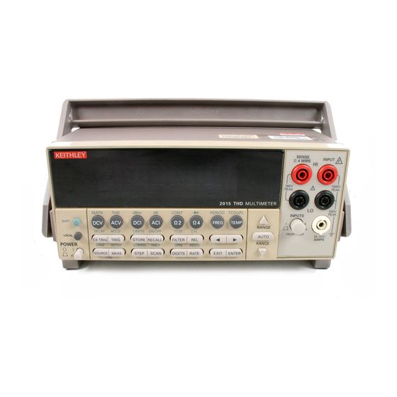
Model 2015
THD Multimeter
Service Manual
REM
STEP
SCAN
CH1
TALK
LSTN
SRQ
SHIFT
TIMER
HOLD
TRIG
FAST
dBm
MATH
T H D
SHIFT
DCV
ACV
DCI
HOLD
DELAY
LIMITS
LOCAL
EX TRIG
TRIG
STORE
POWER
SAVE
SETUP
CONFIG
SOURCE MEAS
STEP
T H D
Contains Servicing Information
CH2
CH3
CH4
CH5
CH6
CH7
CH8
CH9
CH10
MED
SLOW
REL
FILT
AUTO
ERR
BUFFER
STAT
2015 THD MULTIMETER
dB
CONT
PERIOD TCOUPL
Ω2
Ω4
ACI
FREQ
ON/OFF
TEST
CAL
RECALL
FILTER
REL
RS232
HALT
GPIB
SCAN
DIGITS RATE
EXIT
SENSE
Ω 4 WIRE
MATH
REAR
4W
350V
PEAK
INPUTS
TEMP
RANGE
F
R
AUTO
FRONT/REAR
RANGE
ENTER
INPUT
HI
1000V
!
PEAK
LO
500V
PEAK
3A 250V
AMPS
Advertisement
Table of Contents
Troubleshooting

Related Manuals for Keithley 2015


Summary of Contents for Keithley 2015
-
Page 1: Service Manual
TALK REAR LSTN SHIFT 350V 1000V TIMER HOLD TRIG FAST SLOW FILT AUTO BUFFER STAT PEAK PEAK 2015 THD MULTIMETER 500V MATH T H D CONT PERIOD TCOUPL PEAK INPUTS Ω2 Ω4 SHIFT FREQ TEMP RANGE HOLD DELAY LIMITS ON/OFF... - Page 2 WARRANTY Keithley Instruments, Inc. warrants this product to be free from defects in material and workmanship for a period of 3 years from date of shipment. Keithley Instruments, Inc. warrants the following items for 90 days from the date of shipment: probes, cables, rechargeable batteries, diskettes, and documentation.
- Page 3 Model 2015 THD Multimeter Service Manual ©1998, Keithley Instruments, Inc. All rights reserved. Cleveland, Ohio, U.S.A. Third Printing, June 1999 Document Number: 2015-902-01 Rev. C...
- Page 4 Revision B (Document Number 2015-902-01) ..............July 1998 Revision C (Document Number 2015-902-01) ..............June 1999 All Keithley product names are trademarks or registered trademarks of Keithley Instruments, Inc. Other brand names are trademarks or registered trademarks of their respective holders.
-
Page 5: Safety Precautions
As described in the International Electrotechnical Commission (IEC) Standard IEC 664, digital multimeter measuring circuits (e.g., Keithley Models 175A, 199, 2000, 2001, 2002, and 2010) are Installation Category II. All other instruments’ signal terminals are Installation Category I and must not be connected to mains. - Page 6 To maintain protection from electric shock and fire, replacement components in mains circuits, including the power transformer, test leads, and input jacks, must be purchased from Keithley Instruments. Standard fuses, with applicable national safety approvals, may be used if the rating and type are the same. Other components that are not safety related may be purchased from other suppliers as long as they are equivalent to the original component.
-
Page 7: Table Of Contents
Comprehensive calibration ..............2-6 Calibration cycle ................2-6 Recommended equipment .............. 2-6 Aborting calibration ............... 2-7 Front panel calibration ..............2-7 Preparing the Model 2015 for calibration ........2-7 Front panel short and open calibration ........... 2-8 DC volts calibration ............... 2-9... - Page 8 Function generator calibration ............. 2-15 Setting calibration dates and saving calibration ......2-16 Remote calibration ............... 2-16 Preparing the Model 2015 for calibration ........2-17 Short and open calibration ............2-17 DC volts calibration ..............2-18 Resistance calibration ..............2-19 DC current calibration ..............
- Page 9 Analog circuitry ................4-11 Distortion digital circuitry ............4-13 Distortion analog circuitry ............4-15 Sine generator circuitry ..............4-16 Troubleshooting ................4-18 Display board checks ..............4-18 Power supply checks ..............4-19 Digital circuitry checks ..............4-20 Analog signal switching states ............. 4-21 Disassembly Introduction ..................
- Page 10 Calculating generator amplitude accuracy ........A-12 Additional derating factors ............A-12 Optimizing measurement accuracy ..........A-13 DC voltage, DC current, and resistance ........A-13 AC voltage and AC current ............A-13 Temperature ................A-13 Optimizing measurement speed ............. A-14 DC voltage, DC current, and resistance ........A-14 AC voltage and AC current ............
- Page 11 Manufacturing calibration commands ..........B-17 :AC:STEP<14|15> ..............B-17 :DC:STEP0 .................. B-17 Remote error reporting ..............B-18 Error summary ................B-18 Error queue .................. B-20 Status byte EAV (Error Available) bit ......... B-20 Generating an SRQ on error ............B-20 Detecting calibration step completion ..........B-21 Using the *OPC? query ...............
- Page 12 List of Illustrations Performance Verification Connections for DC volts verification ..........1-8 Connections for AC volts verification ..........1-10 Connections for DC current verification ......... 1-12 Connections for AC current verification ......... 1-13 Connections for resistance verification (100 Ω -10M Ω range) ..1-14 Connections for resistance verification (100M Ω...
- Page 13 List of Tables Performance Verification Recommended verification equipment ........... 1-4 DCV reading limits ................ 1-9 ACV reading limits ............... 1-11 DCI limits ..................1-12 ACI limits ..................1-13 Limits for resistance verification ..........1-15 Thermocouple temperature verification reading limits ....1-16 Calibration Recommended equipment for comprehensive calibration .....
- Page 14 ACA signal switching ..............4-23 DCV signal multiplexing and gain ..........4-23 ACV and ACA signal multiplexing and gain ....... 4-23 DCA signal multiplexing and gain ..........4-24 Ω 2 signal multiplexing and gain ..........4-24 Ω 4 signal multiplexing and gain ..........4-24 Switching device locations ............
-
Page 15: Performance Verification
Performance Verification... -
Page 16: Introduction
Performance Verification Introduction Use the procedures in this section to verify that Model 2015 Multimeter accuracy is within the limits stated in the instrument’s one-year accuracy specifications. You can perform these ver- ification procedures: • When you first receive the instrument to make sure that it was not damaged during ship- ment, and that the unit meets factory specifications. -
Page 17: Verification Test Requirements
A relative humidity of less than 80% unless otherwise noted. Warm-up period Allow the Model 2015 Multimeter to warm up for at least one hour before conducting the ver- ification procedures. If the instrument has been subjected to temperature extremes (those outside the ranges stated above), allow additional time for the instrument’s internal temperature to stabilize. -
Page 18: Recommended Test Equipment
10M Ω :±37ppm 100M Ω :±120ppm Fluke 5725A Amplifier: AC Voltage, 50kHz: 700V, ±375ppm Keithley 3930A or 3940 Frequency Synthesizer: 1V RMS, 1kHz, ±5ppm Stanford Research Systems DS-360 Ultra Low Distortion Function Generator: 1kHz, .0.95V RMS sine wave, -100dB THD... -
Page 19: Verification Limits
The following is an example of how reading limits have been calculated: Assume you are testing the 10V DC range using a 10V input value. Using the Model 2015 one-year accuracy specification for 10V DC of ± (30ppm of reading + 5ppm of range), the cal- culated limits are: Reading limits = 10V ±... -
Page 20: Restoring Factory Defaults
Performance Verification Restoring factory defaults Before performing the verification procedures, restore the instrument to its factory defaults as follows: Press SHIFT and then SETUP . The instrument will display the following prompt: RESTORE: FACT. Using either range key, select FACT, then restore the factory default conditions by press- ing ENTER . -
Page 21: Performing The Verification Test Procedures
Do not use autoranging for any verification tests because autorange hysteresis may cause the Model 2015 to be on an incorrect range. For each test signal, you must manually set the correct range for the Model 2015 using the range keys. -
Page 22: Verifying Dc Voltage
Do not exceed 1100V peak between INPUT HI and INPUT LO because instrument damage may occur. Follow these steps to verify DC voltage accuracy: Connect the Model 2015 HI and LO INPUT jacks to the DC voltage calibrator as shown in Figure 1-1. NOTE Use shielded, low-thermal connections when testing the 100mV and 1V ranges to avoid errors caused by noise or thermal effects. -
Page 23: Dcv Reading Limits
Performance Verification Select the DC volts function by pressing the DCV key, and set the Model 2015 to the 100mV range. Select the SLOW integration rate with the RATE key. Set the calibrator output to 0.00000mV DC, and allow the reading to settle. -
Page 24: Verifying Ac Voltage
Verifying AC voltage Check AC voltage accuracy by applying accurate AC voltages at specific frequencies from the AC voltage calibrator to the Model 2015 inputs and verifying that the displayed readings fall within specified ranges. Do not exceed 1100 V peak between INPUT HI and INPUT LO, or 8 × 10 CAUTION V•Hz input, because instrument damage may occur. -
Page 25: Acv Reading Limits
Select the AC volts function by pressing the ACV key, then choose the SLOW integra- tion rate with the RATE key. Set the Model 2015 for the 100mV range; make sure that REL is disabled. Source 1kHz and 50kHz AC voltages for each of the ranges summarized in Table 1-3, and make sure that the respective Model 2015 readings fall within stated limits. -
Page 26: Verifying Dc Current
Verifying DC current Check DC current accuracy by applying accurate DC currents from the DC current calibrator to the AMPS input of the Model 2015 and verifying that the displayed readings fall within spec- ified limits. Follow these steps to verify DC current accuracy: Connect the Model 2015 AMPS and INPUT LO jacks to the calibrator as shown in Figure 1-3. -
Page 27: Verifying Ac Current
Check AC current accuracy by applying accurate AC voltage current at specific frequencies from the AC current calibrator to the Model 2015 input and verifying that the displayed readings fall within specified limits. Follow these steps to verify AC current: Connect the Model 2015 AMPS and INPUT LO jacks to the calibrator as shown in Figure 1-4. -
Page 28: Verifying Resistance
Select the Model 2015 4-wire resistance function by pressing the Ω 4 key, then choose the SLOW integration rate with the RATE key. Set the Model 2015 for the 100 Ω range, and make sure the FILTER is on. Recalculate reading limits based on actual calibrator resistance values. - Page 29 Source the nominal full-scale resistance values for the 100 Ω -10M Ω ranges summarized in Table 1-6, and verify that the readings are within calculated limits. Connect the Model 2015 INPUT and SENSE jacks to the calibrator as shown in Figure 1-6.
-
Page 30: Verifying Temperature
(Use 2-wire connections similar to those shown in Figure 1-1.) Configure the Model 2015 for °C units, type J temperature sensor, and 0°C simulated ref- erence junction as follows: A. Press SHIFT then SENSOR, and note the unit displays the temperature units: UNITS: C. -
Page 31: Verifying Frequency
Verifying frequency Follow the steps below to verify the Model 2015 frequency function: Connect the frequency synthesizer to the Model 2015 INPUT jacks. (See Figure 1-7.) Set the synthesizer to output a 1kHz, 1V RMS sine wave. Select the Model 2015 frequency function by pressing the FREQ key. -
Page 32: Verifying Total Harmonic Distortion
1-18 Performance Verification Verifying total harmonic distortion Follow the steps below to verify the Model 2015 total harmonic distortion function. Connect the low-distortion function generator to the Model 2015 INPUT jacks. (See Figure 1-8.) Figure 1-8 Connections for total harmonic distortion verification... -
Page 33: Verifying Function Generator Amplitude
Performance Verification 1-19 Verifying function generator amplitude Follow the steps below to verify Model 2015 function generator amplitude: Connect the rear panel SOURCE OUTPUT jack to the front panel INPUT jacks. (See Figure 1-9.) Figure 1-9 Connections for function generator amplitude verification... -
Page 34: Calibration
Calibration... -
Page 35: Introduction
Calibration Introduction Use the procedures in this section to calibrate the Model 2015. Calibration procedures include: • Comprehensive calibration: Usually the only calibration required in the field. • Manufacturing calibration: Usually only performed at the factory (unless the unit has been repaired). -
Page 36: Environmental Conditions
A relative humidity of less than 80% unless otherwise noted Warm-up period Allow the Model 2015 Multimeter to warm up for at least one hour before performing calibration. If the instrument has been subjected to temperature extremes (those outside the ranges stated in the above section) allow extra time for the instrument’s internal temperature to stabilize. -
Page 37: Calibration Considerations
• Always let the source signal settle before calibrating each point. • Do not connect test equipment to the Model 2015 through a scanner or other switching equipment. • If an error occurs during calibration, the Model 2015 will generate an appropriate error message. -
Page 38: Calibration Code
Confirm the code by pressing ENTER. The Model 2015 allows you to define a new calibration code. Use the up and down range keys to toggle between yes and no. Choose N if you do not want to change the code. -
Page 39: Comprehensive Calibration
1V RMS sine wave @ 137Hz, -100dB THD 1V RMS sine wave @ 844Hz, -100dB THD Miscellaneous equipment: Keithley 8610 low-thermal shorting plug Double banana plug to double banana plug shielded cable BNC to double banana plug shielded cable * 1kHz specifications. 10mV and 700V points require 1kHz only. -
Page 40: Aborting Calibration
Setting calibration dates Preparing the Model 2015 for calibration Turn on the Model 2015, and allow it to warm up for at least one hour before performing calibration procedure. Select the DCV function, and choose SLOW as the RATE (integration time = 10 PLC). -
Page 41: Front Panel Short And Open Calibration
*Perform AC calibration first if distortion or function generator calibration is done separately. Front panel short and open calibration At the Model 2015 prompt for a front panel short, do the following: Connect the Model 8610 low-thermal short to the instrument front panel INPUT and SENSE terminals as shown in Figure 2-1. -
Page 42: Dc Volts Calibration
After the front panel short and open procedure, the unit will prompt you for the first DC volt- age: +10V. Do the following: Connect the calibrator to the Model 2015 as shown in Figure 2-2. Wait three minutes to allow for thermal equilibrium before proceeding. -
Page 43: Dc Volts Calibration Summary
NOTE If your calibrator cannot output the values recommended in Table 2-3, use the left and right arrow keys, and the up and down range keys to set the Model 2015 display value to match the calibrator output voltage. Table 2-3... -
Page 44: Resistance Calibration
Completing the 100V DC calibration step ends the DC voltage calibration procedure. The Model 2015 will then prompt you to connect 1k Ω . Follow these steps for resistance calibration: Set the calibrator output for resistance, and turn on external sense. -
Page 45: Dc Current Calibration
After the 1M Ω resistance point has been calibrated, the unit will prompt you for 10mA. Fol- low these steps for DC current calibration: Connect the calibrator to the AMPS and INPUT LO terminals of the Model 2015 as shown in Figure 2-3. -
Page 46: Ac Voltage Calibration
Calibration 2-13 AC voltage calibration Follow these steps for AC voltage calibration: Connect the calibrator to the Model 2015 INPUT HI and LO terminals as shown in Figure 2-4. Figure 2-4 Connections for AC volts calibration AC Voltage Calibrator Input HI... -
Page 47: Ac Current Calibration
After the 700VAC at 1kHz point has been calibrated, the unit will prompt you for 100mA at 1kHz. Follow these steps for AC current calibration: Connect the calibrator to the AMPS and INPUT LO terminals of the Model 2015 as shown in Figure 2-3. -
Page 48: Function Generator Calibration
Function generator SOURCE OUTPUT to INPUT Function generator calibration Following distortion calibration, the Model 2015 will prompt you to connect the SOURCE OUTPUT jack to the INPUT jacks: INPUT FGEN Connect the rear panel SOURCE OUTPUT jack to the front panel INPUT jacks (See Figure 2-6.) -
Page 49: Setting Calibration Dates And Saving Calibration
At the end of the calibration procedure, the instrument will display the CALIBRATION COMPLETE message. Press ENTER to continue, and the Model 2015 will prompt you to enter the calibration date and the calibration due date. Set these dates as follows: At the CAL DATE: mm/dd/yy prompt, use the left and right arrow keys, and the range keys to set the calibration date, then press ENTER. -
Page 50: Preparing The Model 2015 For Calibration
Select the DCV function, and choose SLOW as the rate (integration time = 10PLC). Make sure the primary address of the Model 2015 is the same as the address specified in the program that you will be using to send commands. (Use the GPIB key.) -
Page 51: Dc Volts Calibration
Calibration DC volts calibration After front panel short and open steps, do the following: Connect the calibrator to the Model 2015 as shown in Figure 2-2. Allow three minutes for thermal equilibrium. NOTE Although 4-wire connections are shown, the sense leads are connected and discon- nected at various points in this procedure by turning calibrator external sense on or off as appropriate. -
Page 52: Resistance Calibration
• Send the indicated programming command. (Change the command parameter if you are using a different calibration resistance than that shown.) • Wait until the Model 2015 completes each step before continuing. Table 2-10 Resistance calibration programming steps Calibration Calibrator... -
Page 53: Dc Current Calibration
After the 1MΩ resistance point has been calibrated, follow these steps for DC current calibration: Connect the calibrator to the AMPS and INPUT LO terminals of the Model 2015 as shown in Figure 2-3. Perform the calibration steps listed in Table 2-11. For each step: •... -
Page 54: Ac Voltage Calibration
2-21 AC voltage calibration Follow these steps for AC voltage calibration: Connect the calibrator to the Model 2015 INPUT HI and LO terminals as shown in Figure 2-4. Perform the calibration steps summarized in Table 2-12. For each step: •... -
Page 55: Ac Current Calibration
AC current calibration Follow these steps for AC current calibration: Connect the calibrator to the AMPS and INPUT LO terminals of the Model 2015 as shown in Figure 2-3. Perform the calibration steps summarized in Table 2-13. For each step: •... -
Page 56: Function Generator Calibration
Calibration 2-23 Function generator calibration Connect the rear panel SOURCE OUTPUT jack to the front panel INPUT jacks (see Fig- ure 2-6.) Send the following command to complete function generator calibration: :CAL:PROT:FGEN:STEP1 Programming calibration dates Program the present calibration date and calibration due date by sending the following commands: :CAL:PROT:DATE <year>, <month>, <day>... -
Page 57: Manufacturing Calibration
Recommended equipment for manufacturing calibration Keithley 3930A or 3940 Frequency Synthesizer: 1V RMS, 3Hz, ±5ppm 1V RMS, 1kHz, ±5ppm Keithley Model 2001 or 2002 Digital Multimeter: 1V, 3Hz AC, ±0.13% Keithley Model 8610 Low-thermal short Unlocking manufacturing calibration To unlock manufacturing calibration, press and hold in the SOURCE key while turning on the power. -
Page 58: Front Panel Manufacturing Calibration
Perform the entire front panel comprehensive calibration procedure discussed earlier in this section. (See Comprehensive calibration.) Connect the synthesizer to the Model 2015 front panel INPUT jacks as shown in Figure 2-7. Select the front input jacks with the INPUTS switch. -
Page 59: Remote Manufacturing Calibration
Perform the entire remote comprehensive calibration procedure discussed earlier in this section. (See Comprehensive calibration.) Connect the synthesizer to the Model 2015 INPUT jacks as shown in Figure 2-7. Select the front input jacks with the INPUTS switch. Set the synthesizer to output a 1V RMS, 3Hz sine wave, then send the following command: :CAL:PROT:AC:STEP14 <Cal_voltage>... - Page 60 Routine Maintenance...
-
Page 61: Routine Maintenance
Routine Maintenance Introduction The information in this section deals with routine type maintenance that can be performed by the operator and includes procedures for replacing both the line fuse and the amps fuse. Setting the line voltage and replacing the line fuse WARNING Disconnect the line cord at the rear panel, and remove all test leads con- nected to the instrument (front and rear) before replacing the line fuse. -
Page 62: Replacing The Amps Fuse
Release pressure on the jack, and its internal spring will push the fuse carrier out of the socket. Remove the fuse, and replace it with the same type: 3A, 250V, fast blow, Keithley part number FU-99-1. -
Page 63: Routine Maintenance
Routine Maintenance CAUTION Do not use a fuse with a higher current rating than specified, or instrument damage may occur. If the instrument repeatedly blows fuses, locate and cor- rect the cause of the trouble before replacing the fuse. Install the new fuse by reversing the above procedure. -
Page 64: Troubleshooting
Troubleshooting... -
Page 65: Introduction
Troubleshooting Introduction This section of the manual will assist you in troubleshooting and repairing the Model 2015. Included are self-tests, test procedures, troubleshooting tables, and circuit descriptions. It is left to the discretion of the repair technician to select the appropriate tests and documentation needed to troubleshoot the instrument. -
Page 66: Repair Considerations
Troubleshooting Repair considerations Before making any repairs to the Model 2015, be sure to read the following considerations. CAUTION The PC-boards are built using surface mount techniques and require spe- cialized equipment and skills for repair. If you are not equipped and/or qualified, it is strongly recommended that you send the unit back to the fac-... -
Page 67: Power-On Self-Test
Troubleshooting Power-on self-test During the power-on sequence, the Model 2015 will perform a checksum test on its EPROM (U156 and U157) and test its RAM (U151 and U152). If one of these tests fails, the instrument will lock up. -
Page 68: Front Panel Tests
Troubleshooting Front panel tests There are two front panel tests: one to test the functionality of the front panel keys and one to test the display. In the event of a test failure, refer to Display board checks for details on trou- bleshooting the display board. -
Page 69: Principles Of Operation
Troubleshooting Principles of operation The following information is provided to support the troubleshooting tests and procedures covered in this section of the manual. Refer to the following block diagrams: Figure 4-1 — Power supply block diagram Figure 4-2 — Digital circuitry block diagram Figure 4-3 —... -
Page 70: Power Supply Components
Troubleshooting AC power is applied to the AC power module receptacle (J1009). Power is routed through the line fuse and line voltage selection switch of the power module to the power transformer. The power transformer has a total of four secondary windings for the various supplies. AC voltage for the display filaments is taken from a power transformer secondary at F1 and F2, and then routed to the display board. -
Page 71: Display Board
Troubleshooting Display board Display board components are shown in the digital circuitry block diagram in Figure 4-2. Figure 4-2 Digital circuitry block diagram NVRAM U136 U156, U157 U156, U157 Keypad Display Board Display Controller DS401 U401 ADTX XADTX Analog Circuitry XADCLK ADCLK XTAL... -
Page 72: Digital Circuitry
Troubleshooting Display DS401 is the display module, which can display up to 12 alpha-numeric characters and includes the various annunciators. The display uses a common multiplexing scheme with each character refreshed in sequence. U402 and U403 are the drivers for the display characters and annunciators. Note that data for the drivers are serially transmitted from the microcontroller (MOSI and PC1). - Page 73 4-10 Troubleshooting RS-232 interface Serial data transmission and reception is performed by the TXDB and RXDB lines of the MPU. U159 provides the necessary voltage level conversion for the RS-232 interface port. IEEE-488 interface U158, U160, and U161 make up the IEEE-488 interface. U158, a 9914A GPIA, takes care of routine bus overhead such as handshaking, while U160 and U161 provide the necessary buffer- ing and drive capabilities.
-
Page 74: Analog Circuitry
Troubleshooting 4-11 Analog circuitry Refer to Figure 4-3 for the following discussion on analog circuitry. Figure 4-3 Analog circuitry block diagram AMPS Current Shunts K103, R158, R205 Distortion AC Switching Analog & Circuitry Gain (See Figure 4-5) K102, U102, U103, U105, U112, U118, U111, U110 ACV, FREQ... - Page 75 4-12 Troubleshooting AMPS input The ACA or DCA input signal is applied to the Current Shunt circuit, which is made up of K103, R158, and R205. For the 10mA DC range, 10.1 Ω (R158 + R205) is shunted across the input.
-
Page 76: Distortion Digital Circuitry
Troubleshooting 4-13 Distortion digital circuitry Refer to Figure 4-4 for the following discussion on the distortion digital circuitry. Figure 4-4 Distortion digital circuitry block diagram U330 U329 DIGITAL (See Figure 4-2) FPGA EEPROM U327 U326 U312, U313, U316, U317, U318, U319 OPTO ISO OPTO ISO DISTORTION... - Page 77 4-14 Troubleshooting U329 is a ADSP21061 digital signal processor that acquires ADC data, performs all distor- tion and noise calculations, and communicates the results to the microprocessor. The DSP has a 48-bit data bus and provides a 32-bit address bus. It has serial ports for communicating with serial peripherals such as the ADC and DAC converters.
-
Page 78: Distortion Analog Circuitry
Troubleshooting 4-15 Distortion analog circuitry Refer to Figure 4-5 for the following discussion on distortion analog circuitry. Figure 4-5 Distortion analog circuitry block diagram Analog Amplifier Filter ADC Converter Circuitry U309, U310 U311 Distortion (See Figure 4-3) Digital Circuitry (See Figure 4-4) ADC Clock Generator Y301... -
Page 79: Sine Generator Circuitry
4-16 Troubleshooting Sine generator circuitry Refer to Figure 4-6 for the following discussion on the sine generator circuitry. Figure 4-6 Sine generator circuitry block diagram Inv Sine/ Pulse Inv-Sine/pulse K301 50/600 Ohm Comparator Attenuator Filter Source Sine Generator U303, U334 U307 Output U301... - Page 80 FPGA, U334, and opto-isolators U304, U320, and U321. Outputs The Model 2015 has two outputs. U305, U306, U307, and U308 form the main sine wave output stage. The secondary output may be either an inverted sine wave of the same magnitude and fre- quency as the main sine wave output, or a 5V pulse output of the same frequency as the main sine wave.
-
Page 81: Troubleshooting
4-18 Troubleshooting Troubleshooting Troubleshooting information for the various circuits is summarized below. See Principles of operation for circuit theory. Display board checks If the front panel DISP test indicates that there is a problem on the display board, use Table 4-2. -
Page 82: Power Supply Checks
Troubleshooting 4-19 Power supply checks Power supply problems can be checked out using Table 4-3. Table 4-3 Power supply checks Step Item/component Required condition Remarks Line fuse Check continuity. Remove to check. 120V/240V as required. Check power module position. Line voltage Plugged into live receptacle, Check for correct power-up Line power... -
Page 83: Digital Circuitry Checks
4-20 Troubleshooting Digital circuitry checks Digital circuit problems can be checked out using Table 4-4. Table 4-4 Digital circuitry checks Step Item/component Required condition Remarks Power-on test RAM OK, ROM OK. Verify that RAM and ROM are functional. U152 pin 14 Digital common. -
Page 84: Analog Signal Switching States
Troubleshooting 4-21 Analog signal switching states Tables 4-5 through 4-11 provide switching states of the various relays, FETs, and analog switches for the basic measurement functions and ranges. These tables can be used to assist in tracing an analog signal from the input to the A/D multiplexer. Table 4-5 DCV signal switching Range... -
Page 85: Ω 2 Signal Switching
4-22 Troubleshooting Table 4-7 Ω 2 signal switching Range Q101 Q102 Q114 Q136 Q109 K101* K102* Q113 Q105 Q104 Q108 Q121 100 Ω RESET 1k Ω RESET 10k Ω RESET 100k Ω RESET 1M Ω RESET 10MΩ RESET 100MΩ RESET * K101 set states: Pin 8 switched to Pin 7 Pin 3 switched to Pin 4... -
Page 86: Dca Signal Switching
Troubleshooting 4-23 Table 4-10 DCA signal switching Range K103 10mA 100mA Table 4-11 ACA signal switching U105 U105 U111 U105 U103 U103 Range K103 pin 16 pin 1 pin 16 pin 8 pin 16 pin 1 Tables 4-12 through 4-16 can be used to trace the analog signal through the A/D multiplexer (U163) to the final amplifier stage. -
Page 87: Dca Signal Multiplexing And Gain
4-24 Troubleshooting Table 4-14 DCA signal multiplexing and gain Signal U129 U129 U129 Gain Range (U163) pin 1 pin 8 pin 9 (U166) ×100 10mA ×100 100mA ×100 ×10 Table 4-15 Ω 2 signal multiplexing and gain Signal U129 U129 U129 Gain Range... -
Page 88: Troubleshooting
Troubleshooting 4-25 Figure 4-3 provides a block diagram of the analog circuitry. Table 4-17 shows where the var- ious switching devices are located in the block diagram. Table 4-17 Switching device locations Switching devices Analog circuit section (see Figure 4-3) Q101, Q102 SSP (Solid State Protection) Q114, Q136, Q109... -
Page 89: Disassembly
Disassembly... -
Page 90: Introduction
Disassembly Introduction This section explains how to handle, clean, and disassemble the Model 2015 Multimeter. Dis- assembly drawings are located at the end of this section. -
Page 91: Handling And Cleaning
Disassembly Handling and cleaning To avoid contaminating PC board traces with body oil or other foreign matter, avoid touching the PC board traces while you are repairing the instrument. Motherboard areas covered by the shield have high-impedance devices or sensitive circuitry where contamination could cause degraded performance. -
Page 92: Static Sensitive Devices
Use the following precautions to avoid damaging them: CAUTION Many CMOS devices are installed in the Model 2015. Handle all semicon- ductor devices as being static sensitive. •... -
Page 93: Assembly Drawings
Use the following assembly drawings to assist you as you disassemble and re-assemble the Model 2015. Also, refer to these drawings for information about the Keithley part numbers of most mechanical parts in the unit. The drawings are located at the end of this section of the manual. -
Page 94: Disassembly Procedures
Disassembly Disassembly procedures Case cover removal Follow the steps below to remove the case cover to gain access to internal parts. WARNING Before removing the case cover, disconnect the line cord and any test leads from the instrument. Remove Handle — The handle serves as an adjustable tilt-bail. Adjust its position by gently pulling it away from the sides of the instrument case and swinging it up or down. -
Page 95: Dsp Board Removal
Disassembly Disconnect the front and rear input terminals. You must disconnect these input terminal connections for both the front and rear inputs: • INPUT HI and LO • SENSE HI and LO • AMPS Remove all the connections except the front AMPS connection by pulling the wires off the pin connectors. -
Page 96: Front Panel Disassembly
Disassembly Front panel disassembly Use the following procedures to remove the display board and/or the pushbutton switch pad: NOTE You must first remove the case cover, the front/rear input switch, and the front input terminal wires as described earlier in this section. Unplug the display board ribbon cable from connector J1014. -
Page 97: Instrument Reassembly
SENSE LO Gray White/Gray AMPS White — Power module wire connections Use the information in Table 5-2 and DETAIL B of drawing 2015-050 to connect power mod- ule wires. Table 5-2 Power module wire colors Location Wire color Top wire... -
Page 98: Changing Trigger Link Lines
Disassembly Changing trigger link lines The Model 2015 uses two lines of the Trigger Link rear panel connector as External Trigger (EXT TRIG) input and Voltmeter Complete (VMC) output. At the factory, line 1 is configured as VMC and line 2 as EXT TRIG. -
Page 99: Main Cpu Firmware Replacement
Disassembly 5-11 Main CPU firmware replacement Changing the firmware may be necessary as upgrades become available. The firmware revi- sion levels for the main and front panel CPUs are displayed during the power-on sequence. (The main firmware revision level is displayed on the left; the front panel firmware revision level is displayed on the right.) For example: REV: A01 A02 indicates a main firmware revision level of A01 and a front panel firmware revision level of A02. - Page 100 5-12 Disassembly...
-
Page 101: Replaceable Parts
Replaceable Parts... -
Page 102: Introduction
Model 2015. Parts lists The electrical parts lists for the Model 2015 are shown in Tables 6-1 to 6-4. For part numbers to the various mechanical parts and assemblies, use the Miscellaneous parts list and the assem- bly drawings provided at the end of Section 5. -
Page 103: Dmm (Mother) Board Parts List
Replaceable Parts Table 6-1 DMM (mother) board parts list Keithley Circuit designation Description part no. AT101 IC, DUAL HIGH CMR/SPEED OPTO, IC-588 HCPL-2631 C102 CAP, .01UF, 10%, 1000V, CERAMIC C-64-.01 C103,128,149,161,167,169,172,178,223, CAP, .1UF, 10%, 25V, CERAMIC C-495-.1 C104 CAP, 100UF, 20%, 63V, ALUM ELEC... - Page 104 Replaceable Parts Table 6-1 DMM (mother) board parts list (continued) Keithley Circuit designation Description part no. C209 CAP, 22UF, 20%, 25V, TANTALUM C-440-22 C240,244 CAP, 1000pF, 20%, 50V, CERAMIC C-418-1000P C241 CAP, .01UF, 10%, 50V, CERAMIC C-491-.01 C242,243 CAP, .01UF, 10%, 50V, CERAMIC C-491-.01...
- Page 105 Replaceable Parts Table 6-1 DMM (mother) board parts list (continued) Keithley Circuit designation Description part no. Q111,116,Q129 TRANS, PNP, MMBT3906L TG-244 Q117,121,122 N-CHANNEL SILICON JFET TG-351 Q119 TRANS, P CHANNEL JFET, J270 TG-166 Q127,131-133 TRANS, N-MOSFET, VN0605T TG-243 Q136,137 TRANS, N CHANNEL JFET, SNJ132199...
- Page 106 Replaceable Parts Table 6-1 DMM (mother) board parts list (continued) Keithley Circuit designation Description part no. R160,167,172 RES, 1M, 1%, 100MW, THICK FILM R-418-1M R161,178,184,187,213,248,257,308, RES, 100, 1%, 100MW, THICK FILM R-418-100 331,332 R168 RES, 270, 5%, 250mW, METAL FILM...
- Page 107 Replaceable Parts Table 6-1 DMM (mother) board parts list (continued) Keithley Circuit designation Description part no. R309 RES, 1K, .1%, 1/10W, METAL FILM R-263-1K R310 RES, 9.09K, .1%, 1/10W, METAL FILM R-263-9.09K R311 RES, 392, 1%, 100MW, THICK FILM R-418-392...
- Page 108 IC, 32KX8 STAT CMOS RAM, D43256C LSI-93-100 U154 IC, QUAD D FLIP FLOP W/CLK, RESET IC-923 74HC175 U155 IC, OPTOCOUPLER, 2601 IC-239 U156 PROGRAMMED ROM 2015-804* U157 PROGRAMMED 2015-803* U158 IC, GPIB ADAPTER, 9914A LSI-123 U159 IC, +5V RS-232 TRANSCEIVER, MAX202 IC-952 U160...
-
Page 109: Display Board Parts List
Replaceable Parts Table 6-2 Display board parts list Keithley Circuit designation Description part no. C401,402,411 CAP, .1UF, 20%, 50V, CERAMIC C-418-.1 C403,404,405,407,409,410,412 CAP, .1UF, 10%, 25V, CERAMIC C-495-.1 C406,408 CAP, 33PF, 10%, 100V, CERAMIC C-451-33P C413 CAP, 22UF, 20%, 6.3, TANTALUM... -
Page 110: Distortion (Dsp) Board Parts List
6-10 Replaceable Parts Table 6-3 Distortion (DSP) board parts list Keithley Circuit designation Description part no. C301,310,352,505,508,532,538,571 CAP, .1UF, 10%, 25V, CERAMIC C-495-.1 C302,313,323,354,560,561,378-387, CAP, .01UF, 10%, 50V, CERAMIC C-491-.01 C303,325,355,399,511,550,573,344 CAP, 10U, 20%, 16V, TANTALUM C-546-10 C304,305,396,397 CAP, 2200P, 1%, 50V, CERAMIC... - Page 111 Replaceable Parts 6-11 Table 6-3 Distortion (DSP) board parts list (continued) Keithley Circuit designation Description part no. HS331 HEAT SINK HS-55 J1018,1019,1021 CONNECTOR, HEADER CS-784-6 J1020 CONN, MALE 3 PIN CS-784-3 J1028,1029 CONN, BNC RIGHT ANGLE PLASTIC CS-506 J1030 CONN, DUAL 10-PIN-BERG...
- Page 112 6-12 Replaceable Parts Table 6-3 Distortion (DSP) board parts list (continued) Keithley Circuit designation Description part no. R392-394,542,547,553-555 RES, 10K, 1%, 100MW, THICK FILM R-418-10K R396-399 RES, 274, 1%, 100MW, THICK FILM R-418-274 R502 RES, 4.75K, 1%, 100MW, THICK FILM R-418-4.75K...
- Page 113 Replaceable Parts 6-13 Table 6-3 Distortion (DSP) board parts list (continued) Keithley Circuit designation Description part no. U315 PROGRAMMED ROM 2015-806* U316-321,324 IC, OPTOCOUPLER, 2601 IC-239 U326 PROGRAMMED ROM 2015-807* U329 LARGE SCALE IC SMT LSI-217 U330 PROGRAMMED ROM 2015-805*...
-
Page 114: Mechanical Parts List
6-14 Replaceable Parts Table 6-4 Mechanical parts list Qty. Description Keithley part no. BANANA JACK, PUSH-IN BLACK BJ-14-0 BANANA JACK, PUSH-IN RED BJ-14-2 BEZEL, REAR 428-303D CHOKE CH-58-1A CONTACT, CURRENT INPUT 2001-313C COVER 2000-307C DISPLAY LENS 2015-311A FOOT 428-319A FOOT, EXTRUDED... - Page 115 Specifications...
- Page 116 Specifications DISTORTION CHARACTERISTICS VOLTAGE RANGE: 100mV, 1V, 10V, 100V, 750V (user selectable). INPUT IMPEDANCE: 1MΩ paralleled by <100pF. DISPLAY RANGE: 0–100% or 0–100.00dB. RESOLUTION: 0.0001% or 0.00001dB. FUNDAMENTAL FREQUENCY RANGE: 20Hz–20kHz. HARMONIC FREQUENCY RANGE: 40Hz–50kHz. FREQUENCY RESOLUTION: 0.008Hz. FREQUENCY ACCURACY: ±0.01% of reading. FREQUENCY TEMPERATURE COEFFICIENT: ≤100ppm over operating temperature range.
- Page 117 Specifications Frequency Sweep Reading Rate NUMBER OF FREQUENCIES TIME (seconds) Notes 1. Input signal at full scale. ≥20% of range and harmonics >–65dB. 2. V 3. Speeds are for default operating conditions (*RST), and display off, auto range off, binary data transfer, trig delay = 0. 4.
- Page 118 Specifications INV/PULSE OUTPUT (PULSE MODE): Frequency: Same as source output. Duty Cycle: 45% ±3%. Output Impedance: Same output impedance as the source output. Amplitude: 0.0V ±0.07V to 4.9V ±0.12V pulse open circuit 1, 3 1, 3 0.0V ±0.05V to 3.3V ±0.08V pulse 100Ω load Overshoot: 1.0V maximum pulse open circuit 0.2V maximum with 100Ω...
- Page 119 Specifications DC OPERATING CHARACTERISTICS FUNCTION DIGITS READINGS/s PLCs DCV (all ranges), ⁄ 2 3, 4 2 3, 7 DCI (all ranges), and ⁄ 2W Ohms (<10M range) ⁄ 2 3, 5 ⁄ 2 3, 5 ⁄ ⁄ 1000 0.04 ⁄ 2000 0.01 DC SYSTEM SPEEDS...
- Page 120 Specifications TRUE RMS AC VOLTAGE AND CURRENT CHARACTERISTICS ACCURACY : ±(% of reading + % of range), 23°C ±5 °C VOLTAGE CALIBRATION 3 Hz– 10 Hz– 20 kHz– 50 kHz– 100 kHz– RANGE RESOLUTION CYCLE 10 Hz 20 kHz 50 kHz 100 kHz 300 kHz 100.0000 mV...
-
Page 121: Math Functions
Specifications AC GENERAL INPUT IMPEDANCE: 1MΩ ±2% paralleled by <100pF. ACV INPUT PROTECTION: 1000Vp. MAXIMUM DCV: 400V on any ACV range. ACI INPUT PROTECTION: 3A, 250V fuse. BURDEN VOLTAGE: 1A Range: <0.3V rms. 3A Range: <1V rms. SHUNT RESISTOR: 0.1Ω on all ACI ranges. AC CMRR: >70dB with 1kΩ... -
Page 122: Temperature Characteristics
Specifications Frequency Notes 1. Specifications are for squarewave inputs >10% of ACV range, except 100mV range. On 100mV range frequency must be >10Hz if voltage is <20mV. 2. 20% overrange on all ranges except 750V range. TEMPERATURE CHARACTERISTICS THERMOCOUPLE 2, 3, 4 90 DAY/1 YEAR (23°C ±... -
Page 123: Accuracy Calculations
Specifications Accuracy calculations The information below discusses how to calculate accuracy for both DC and AC characteristics. Calculating DC characteristics accuracy DC characteristics accuracy is calculated as follows: Accuracy = ±(ppm of reading + ppm of range) (ppm = parts per million, and 10ppm = 0.001%) As an example of how to calculate the actual reading limits, assume that you are measuring 5V on the 10V range. -
Page 124: Calculating Dbm Characteristics Accuracy
A-10 Specifications Calculating dBm characteristics accuracy As an example of how to calculate the actual reading limits for a 13dBm measurement with a reference impedance of 50 Ω , assume an applied signal 0.998815V. The relationship between voltage and dBm is as follows: dBm = 10 log --------------------------- - From the previous example on calculating DC characteristics accuracy, it can be shown that... -
Page 125: Calculating Db Characteristics Accuracy
Specifications A-11 Calculating dB characteristics accuracy The relationship between voltage and dB is as follows: dB = 20 log -------------- - As an example of how to calculate the actual readings limits for dB, with a user-defined V of 10V, you must calculate the voltage accuracy and apply it to above equation. To calculate a -60dB measurement, assume 10mVRMS for a V of 10V. -
Page 126: Optimizing Measurement Accuracy
A-12 Specifications Optimizing measurement accuracy The configurations listed below assume that the multimeter has had factory setups restored. DC voltage, DC current, and resistance: • Select 6 digits, 10 PLC, filter ON (up to 100 readings), fixed range. • Use REL on DC voltage and 2-wire resistance measurements. •... -
Page 127: B Calibration Reference
Calibration Reference... -
Page 128: Calibration Reference
Introduction This appendix contains detailed information about the various Model 2015 remote calibration commands. Section 2 of this manual covers detailed calibration procedures. For information about additional commands to control other instrument functions, refer to the Model 2015 User's Manual. -
Page 129: Command Summary
Save cal constants to EEROM. :DATE <year>, <month>, <day> Send cal date to 2015. :DATE? Request cal date from 2015. :NDUE <year>, <month>, <day> Send next due cal date to 2015. :NDUE? Request next due cal date from 2015. DC cal steps. :STEP0... - Page 130 Calibration Reference Table B-1 Remote calibration command summary (continued) Command Description :CALibration Calibration root command. :PROTected AC cal steps. :STEP1 10mV AC at 1kHz step. :STEP2 100mV AC at 1kHz step. :STEP3 100mV AC at 50kHz step. :STEP4 1V AC at 1kHz step. :STEP5 1V AC at 50kHz step.
-
Page 131: Miscellaneous Calibration Commands
Example Send default code of KI002015. :CAL:PROT:CODE 'KI002015' :COUNt? (:CALibration:PROTected:COUNt?) Purpose To determine how many times the Model 2015 has been calibrated. Format :cal:prot:coun? Response <n> Calibration count. Description The :COUNt? command allows you to determine how many times the Model 2015 has been calibrated. -
Page 132: Init
Format :cal:prot:init Parameter None Description The :INIT command enables Model 2015 calibration when performing these procedures over the bus. This command must be sent to the unit after sending the :CODE command, but before sending any other calibration command. NOTE The :INIT command should be sent only once before performing either DC, AC, or factory calibration. -
Page 133: Lock?
Response 0 Comprehensive calibration locked. 1 Comprehensive calibration unlocked. Description The :LOCK? query requests status from the Model 2015 on calibration locked/unlocked state. Calibration must be enabled sending the :CODE com- mand before calibration can be performed. Example Request cal lock state. -
Page 134: Date
Calibration Reference :DATE (:CALibration:PROTected:DATE) Purpose To send the calibration date to the instrument. Format :cal:prot:date <year>, <month>, <day> Parameters <year> = 1998 to 2097 <month> = 1 to 12 <day> = 1 to 31 Query format :cal:prot:date? Response <year>, <month>, <day> Description The :DATE command allows you to store the calibration date in instrument memory for future reference. -
Page 135: Dc Calibration Commands
Calibration Reference DC calibration commands The :DC commands perform calibration of the DCV, DCI, and ohms functions. Table B-2 summarizes these calibration commands along with parameter limits. Table B-2 DC calibration commands Command Description Parameter limits :CALibration :PROTected :STEP1 Front terminal short circuit. :STEP2 Open circuit. -
Page 136: Step2
B-10 Calibration Reference :STEP2 (:CALibration:PROTected:DC:STEP2) Purpose To perform front terminal open-circuit calibration. Format :cal:prot:dc:step2 Parameter None Description :STEP2 performs the open-circuit calibration step in the comprehensive cal- ibration procedure. Disconnect all cables and accessories from the input jacks before sending this command. Example Perform open circuit calibration. -
Page 137: Step5
Calibration Reference B-11 :STEP5 (:CALibration:PROTected:DC:STEP5) Purpose To program the 100V DC comprehensive calibration step. Format :cal:prot:dc:step5 <Cal_voltage> Parameter <Cal_voltage> = 90 to 110 [V] Description :STEP5 programs the 100V DC comprehensive calibration step. The allow- able range of the calibration voltage parameter is from 90 to 110, but 100 is recommended for best results. -
Page 138: Step8
B-12 Calibration Reference :STEP8 (:CALibration:PROTected:DC:STEP8) Purpose To program the 100kΩ 4-wire comprehensive calibration step. Format :cal:prot:dc:step8 <Cal_resistance> Parameter <Cal_resistance> = 90E3 to 110E3 [Ω] Description :STEP8 programs the 100kΩ 4-wire resistance comprehensive calibration step. The allowable range of the calibration resistance parameter is from 90E3 to 110E3, but 100E3 is recommended for best results. -
Page 139: Step11
Calibration Reference B-13 :STEP11 (CALibration:PROTected:DC:STEP11) Purpose To program the 100mA comprehensive calibration step. Format :cal:prot:dc:step11 <Cal_current> Parameter <Cal_current> = 90E-3 to 110E-3 [A] Description :STEP11 programs the 100mA comprehensive calibration step. The allow- able range of the calibration current parameter is from 90E-3 to 110E-3. Use the 100E-3 value whenever possible for best results. -
Page 140: Ac Calibration Commands
B-14 Calibration Reference AC calibration commands The :AC commands perform comprehensive (user) calibration of the ACV and ACI functions. Table B-3 summarizes these calibration commands. Table B-3 AC calibration commands Command Description :CALibration :PROTected :STEP1 10mV AC at 1kHz calibration step. :STEP2 100mV AC at 1kHz calibration step. -
Page 141: Ac:step
Calibration Reference B-15 :AC:STEP<n> (CALibration:PROTected:AC:STEP<n>) Purpose To program individual AC calibration steps. Format :cal:prot:ac:step<n> Parameters 10mV AC at 1kHz calibration step. 100mV AC at 1kHZ calibration step. 100mV AC at 50kHz calibration step. 1V AC at 1kHz calibration step. 1V AC at 50kHz calibration step. 10V AC at 1kHz calibration step. -
Page 142: Distortion And Function Generator Calibration Commands
B-16 Calibration Reference Distortion and function generator calibration commands Table B-4 summarizes distortion and function generator calibration commands. Table B-4 Distortion and function generator calibration commands Command Description :CALibration :PROTected :DIST Distortion calibration commands. :STEP1 1V RMS at 137Hz step. :STEP2 1V RMS at 844Hz step. -
Page 143: Manufacturing Calibration Commands
Calibration Reference B-17 Manufacturing calibration commands Three calibration steps are only performed at the factory or when the unit has been repaired: 1V AC at 3Hz :CALibration:PROTected:AC:STEP14 1V AC at 1kHz :CALibration:PROTected:AC:STEP15 Rear terminal short circuit :CALibration:PROTected:DC:STEP0 :AC:STEP<14|15> (CALibration:PROTected:AC:STEP<14|15>) Purpose To program individual AC manufacturing calibration steps. -
Page 144: Remote Error Reporting
Calibration Reference Remote error reporting Methods to detect and determine the nature of calibration errors are discussed below. Error summary Table B-5 summarizes Model 2015 calibration errors. Table B-5 Calibration error summary Error number and description +400, "10 vdc zero error"... - Page 145 Calibration Reference B-19 Table B-5 Calibration error summary (continued) Error number and description +450, "100m vac dac error" +451, "1 vac dac error" +452, "10 vac dac error" +453, "100 vac dac error" +454, "100m vac zero error" +455, "100m vac full scale error" +456, "1 vac zero error"...
-
Page 146: Error Queue
Calibration Reference Error queue As with other Model 2015 errors, any calibration error will be reported in the bus error queue. You can read this queue by using the :SYST:ERR? query. The Model 2015 will respond with the appropriate error message, as summarized in Table B-5. -
Page 147: Detecting Calibration Step Completion
Calibration Reference B-21 Detecting calibration step completion When sending remote calibration commands, you must wait until the instrument completes the current operation before sending a command. You can use either *OPC? or *OPC to help determine when each calibration step is completed. Using the *OPC? query With the *OPC? (operation complete) query, the instrument will place an ASCII 1 in the out- put queue when it has completed each step. -
Page 148: Generating An Srq On Calibration Complete
An IEEE-488 bus SRQ (service request) can be used to detect operation complete instead of repeatedly polling the Model 2015. To use this method, send both *ESE 1 and *SRE 32 to the instrument, then include the *OPC command at the end of each calibration command line, as covered above. -
Page 149: C Calibration Program
Calibration Program... -
Page 150: Introduction
Calibration Program Introduction This appendix includes a calibration program written in BASIC to help you calibrate the Model 2015. Refer to Section 2 for more details on calibration procedures, equipment, and connections. Computer hardware requirements The following computer hardware is required to run the calibration program: •... -
Page 151: General Program Instructions
Turn on the computer, the Model 2015, and the calibrator. Allow the Model 2015 and the calibrator to warm up for at least one hour before performing calibration. Make sure the Model 2015 is set for a primary address of 16. (Use the front panel GPIB key to check or change the address.) Make sure the calibrator primary address is at its factory default setting of 4. - Page 152 PRINT #1, "OUTPUT 4;OPER" END SELECT IF I > 2 AND I < 26 THEN GOSUB Settle PRINT #1, "OUTPUT 16;"; C$; Cmd$; ";*OPC" ' Send cal command to 2015. GOSUB CalEnd ' Wait until cal step ends. GOSUB ErrCheck ' Check for cal error.
- Page 153 Calibration Program KeyCheck: Check for key press routine. WHILE INKEY$ <> "": WEND ' Flush keyboard buffer. PRINT : PRINT "Press any key to continue (ESC to abort program)." DO: I$ = INKEY$: LOOP WHILE I$ = "" IF I$ = CHR$(27) THEN GOTO EndProg ' Abort if ESC is pressed.
- Page 154 Calibration Program DATA "OUT 100 MV,50 KHZ","AC:STEP3" DATA "OUT 1 V,1 KHZ","AC:STEP4" DATA "OUT 1 V,50 KHZ","AC:STEP5" DATA "OUT 10 V,1 KHZ","AC:STEP6" DATA "OUT 10 V,50 KHZ","AC:STEP7" DATA "OUT 100 V,1 KHZ","AC:STEP8" DATA "OUT 100 V,50 KHZ","AC:STEP9" DATA "OUT 700 V,1 KHZ","AC:STEP10" DATA "OUT 100 MA,1 KHZ","AC:STEP11"...
-
Page 155: Distortion Characteristics
Index DISP test 4-5 Display board 4-8 Aborting calibration 2-7 Display board checks 4-18 AC calibration commands B-14 Distortion analog circuitry 4-15 AC current calibration 2-14, 2-22 Distortion and function generator calibration AC voltage and AC current A-13, A-14 commands B-16 AC voltage calibration 2-13, 2-21 Distortion calibration 2-14, 2-22 :AC:STEP<14|15>... -
Page 156: Optimizing Measurement Accuracy
Power module wire connections 5-9 Power supply 4-6 Power supply checks 4-19 Temperature A-13, A-14 Power-on self-test 4-4 Test considerations 1-7 Preparing the Model 2015 for Test summary 1-7 calibration 2-7, 2-17 Troubleshooting 4-1, 4-18 Principles of operation 4-6 Programming calibration dates 2-23... - Page 157 Service Form Model No. _____________ Serial N o. ___________________ Date________________ Name and Telephone No. _________________________________________________________ Company ______________________________________________________________________ List all control settings, describe problem and check boxes that apply to problem. _________________________ __________________________________________________________________________________________ __________________________________________________________________________________________ Intermittent Analog output follows display Particular range or function bad; specify _______________________________ IEEE failure Obvious problem on power-up...
- Page 158 Keithley Instruments, Inc. 28775 Aurora Road Cleveland, Ohio 44139 Printed in the U.S.A.
Need help?
Do you have a question about the 2015 and is the answer not in the manual?
Questions and answers