Keithley 2001 Operator's Manual
Hide thumbs
Also See for 2001:
- Operator's manual (476 pages) ,
- Repair manual (168 pages) ,
- Calibration manual (107 pages)
Table of Contents
Advertisement
Quick Links
Advertisement
Chapters
Table of Contents

Subscribe to Our Youtube Channel
Related Manuals for Keithley 2001


Summary of Contents for Keithley 2001
- Page 1 Model 2001 Multimeter Operator’s Manual Contains Operating Information...
- Page 2 Keithley Instruments, Inc. • 28775 Aurora Road • Cleveland, OH 44139 • 440-248-0400 • Fax: 440-248-6168 • http://www.keithley.com CHINA: Keithley Instruments China • Yuan Chen Xin Building, Room 705 • 12 Yumin Road, Dewai, Madian • Beijing 100029 • 8610-62022886 • Fax: 8610-62022892 FRANCE: Keithley Instruments SARL •...
- Page 3 Model 2001 Multimeter Operator’s Manual ©1992, Keithley Instruments, Inc. All rights reserved. Cleveland, Ohio, U.S.A. Seventh Printing, June 1999 Document Number: 2001-900-01 Rev. G...
- Page 4 Revision F (Document Number 2001-900-01) ..................July 1998 Revision G (Document Number 2001-900-01) ..................June 1999 All Keithley product names are trademarks or registered trademarks of Keithley Instruments, Inc. Other brand and product names are trademarks or registered trademarks of their respective holders.
-
Page 5: Safety Precautions
(IEC) Standard IEC 664, digital multimeter measuring circuits The types of product users are: (e.g., Keithley Models 175A, 199, 2000, 2001, 2002, and 2010) are Installation Category II. All other instruments’ signal terminals are Responsible body is the individual or group responsible for the use Installation Category I and must not be connected to mains. - Page 6 NOT as safety earth ground connections. leads, and input jacks, must be purchased from Keithley Instru- ments. Standard fuses, with applicable national safety approvals, If you are using a test fixture, keep the lid closed while power is ap- may be used if the rating and type are the same.
-
Page 7: Table Of Contents
Table of Contents General Information Introduction ................................. 1-1 Features ................................1-1 Warranty information............................1-2 Manual addenda ..............................1-2 Safety symbols and terms ........................... 1-2 Specifications ..............................1-2 Inspection ................................1-2 Options and accessories ............................1-2 Getting Started Introduction ................................. 2-1 Front and rear panel summary .......................... - Page 8 Front Panel Operation Introduction ................................. 3-1 Power-up procedure............................. 3-1 3.2.1 Line power connections..........................3-1 3.2.2 Line fuse replacement..........................3-2 3.2.3 Power-up sequence............................3-2 3.2.4 High energy circuit safety precautions ......................3-4 3.2.5 Power-on default conditions........................3-4 3.2.6 Warm-up period............................3-4 3.2.7 IEEE-488 primary address ..........................
- Page 9 3.10 Math .................................. 3-92 3.10.1 mX+b ................................ 3-92 3.10.2 Percent............................... 3-93 3.10.3 Percent deviation ............................3-93 3.10.4 Configuring math ............................3-93 3.10.5 Enabling math ............................3-94 3.10.6 Calculate multiple display......................... 3-94 3.11 Scanning................................3-94 3.11.1 Scanning overview ............................ 3-94 3.11.2 Front panel scanner controls ........................
- Page 10 4.8.8 SPE, SPD (serial polling) .......................... 4-27 Programming syntax............................4-29 4.10 Common commands............................4-35 *CLS clear status..........................4-36 4.10.1 *ESE event enable..........................4-36 4.10.2 *ESE? event enable query ........................4-38 4.10.3 *ESR? event status register query ......................4-38 4.10.4 *IDN? ...
- Page 11 4.19.19 :RTD commands ............................ 4-156 4.19.20 :SPRTD ..............................4-159 4.19.21 :TCouple:TYPE <name> ........................4-160 4.19.22 :RJUNctionX............................4-161 4.19.23 :REAL commands ..........................4-163 4.19.24 :OCOMpensated <b> ..........................4-165 4.19.25 :SENSe2 subsystem ..........................4-165 4.20 :SOURce subsystem............................4-167 4.21 :STATus subsystem ............................4-169 4.21.1 [:EVENt]? ...............................
- Page 12 APPENDICES Specifications ............................A-1 Default Conditions............................B-1 IEEE-488.2 Common Commands ......................C-1 SCPI Command Subsystems ........................D-1 Interface Function Codes..........................E-1 ASCII Character Codes and IEEE-488 Multiline Interface Command Messages ........F-1 Controller Programs ........................... G-1 IEEE-488 Bus Overview ..........................H-1 IEEE-488 Conformance Information ......................
- Page 13 List of Illustrations Getting Started Figure 2-1 Model 2001 front panel..........................2-2 Figure 2-2 Model 2001 rear panel ..........................2-3 Figure 2-3 Simplified model of measurement operation ....................2-6 Figure 2-4 Typical DC voltage connections ......................... 2-9 Front Panel Operation Figure 3-1 Model 2001 display formats ........................
- Page 14 IEEE-488 connections ..........................4-2 Figure 4-3 IEEE-488 connector location ........................4-2 Figure 4-4 Contact assignments ............................ 4-3 Figure 4-5 Model 2001 status register structure......................4-6 Figure 4-6 Standard event status ........................... 4-7 Figure 4-7 Operation event status ..........................4-8 Figure 4-8 Arm event status ............................
- Page 15 Figure 4-34 Measurement Transition Filter........................ 4-182 Figure 4-35 Questionable Transition Filter ........................ 4-183 Figure 4-36 Operation Transition Filter........................4-184 Figure 4-37 Trigger Transition Filter.......................... 4-185 Figure 4-38 Arm Transition Filter ..........................4-186 Figure 4-39 Sequence Transition Filter ........................4-187 Figure 4-40 Key-press codes ............................
- Page 16 List of Tables Getting Started Table 2-1 DCV multiple displays..........................2-5 Table 2-2 Menu summary ............................2-6 Table 2-3 CONFIGURE DCV menu structure ......................2-10 Table 2-4 Multiple displays for recalled readings ....................2-12 Table 2-5 Burst mode availability ..........................2-12 Table 2-6 Abbreviated common command summary ....................
- Page 17 Auto resolution; DCV, Ω 2 and Ω 4......................4-140 Table 4-24 Table 4-25 Auto resolution; TEMP ........................... 4-141 Table 4-26 RTD coefficients to Model 2001 coefficients ..................4-159 Table 4-27 SOURce command summary ........................4-167 Table 4-28 STATus command summary........................4-169 Table 4-29 SYSTem command summary........................
- Page 18 IEEE command groups ..........................H-8 Table I-1 IEEE-488 documentation requirements ....................... I-1 Table I-2 Coupled commands............................I-2 Table J-1 Syntax of SCPI confirmed commands implemented by Model 2001............J-1 Table J-2 Syntax of non-SCPI commands implemented by Model 2001..............J-7 xiii...
-
Page 19: General Information
This section contains general information about the Model the IEEE-488 bus. For example, the buffer can be pro- 2001 Multimeter. It is arranged in the following manner: grammed to store up to 850 readings at 4.5 digits, or up to 250 time-stamped readings at 6.5 digits. The Model Features 2001 can be configured with memory options that ex-... -
Page 20: Warranty Information
Always Model 1050 Padded Carrying Case — A carrying case for read the associated information very carefully before per- a Model 2001 or a Model 7001. Includes handles and shoul- forming the indicated procedure. der strap. - Page 21 Model 5806 Kelvin Clip Lead Set — Includes two Kelvin Model 4288-3 Side-by-side Rack Mount Kit — Mounts a clip test leads (0.9m) with banana plug termination. De- Model 2001 and a Model 199 side-by-side in a standard 19- signed for instruments that measure 4-terminal resistance. A inch rack.
-
Page 22: Getting Started
IEEE-488 2.2.2 Rear panel bus, including programming examples. The rear panel of the Model 2001 is shown in Figure 2-2. NOTE This figure also includes abbreviated information that should The IEEE-488 bus is also referred to as be reviewed before operating the instrument. -
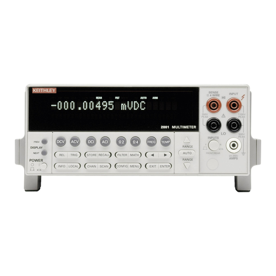
Page 23: Figure 2-1 Model 2001 Front Panel
PREV: Moves to previous multiple display of a function resistance measurements NEXT: Moves to next multiple display of a function INPUTS POWER Selects input connections on front or rear panels 0 = OFF 10 CAL 1 = ON Enables calibration functions Figure 2-1 Model 2001 front panel... -
Page 24: Figure 2-2 Model 2001 Rear Panel
BNC CONNECTIONS LO (Chassis) INPUT CONNECTIONS SCANNER Optional Model 2001-SCAN Scanner Card installs in this slot INPUT HI and LO: Used for making DC volts, AC volts, and 2-wire resistance measurements. AMPS FUSE AMPS: Used in conjunction with INPUT LO to make DC Holds current input fuse (2A, 250V, fast blow, 5×20mm) -
Page 25: Front Panel Display
In some cases, menu selections branch off to further define the options, such as the following for the SPEED option: In the multiple display mode, the Model 2001 can show the readings of up to three separate measurements. For example,... -
Page 26: Table 2-1 Dcv Multiple Displays
NEXT ↓ ↑ PREV +00.00000 VDC CH02 Readings of adjacent internal channels CH01=+00.0000 V CH03=+00.0000 V (with Model 2001-SCAN option). NEXT ↓ ↑ PREV Note: Press the NEXT and PREV DISPLAY keys to scroll through the multiple displays (with wraparound). -
Page 27: Overview Of Measurement Process
Getting Started Table 2-2 Message displays Menu summary While operating the Model 2001, the front panel display is also used for showing status and error messages. These mes- Action Description sages are shown to inform you of parameter conflicts, trigger CONFIG-DCV Press the CONFIG key, then the DCV overruns, etc. -
Page 28: Idle
With one of the other scan sources selected (External, Manual, GPIB, Trigger Link, Timer, or When the Model 2001 is taken out of the idle state by press- Hold), the instrument waits until the appropriate event oc- ing TRIG (or sending the :INIT or :INIT:CONT ON com- curs. -
Page 29: Initial Configuration
DC voltage are: • Measurement speed (integration time) Normal, 1 The Model 2001 can save from one to ten user setups in power line cycle. memory, depending on the installed memory option. You can •... -
Page 30: Figure 2-4 Typical Dc Voltage Connections
400Hz). 2. Using the set of supplied test leads, connect the Model • Digital filter Advanced, 10 readings, 1% noise toler- 2001 to a DC voltage source (e.g., a battery) as shown in Figure 2-4. ance, moving average, enabled. -
Page 31: Table 2-3 Configure Dcv Menu Structure
Getting Started Table 2-3 CONFIGURE DCV menu structure Menu item Description SPEED Measurement speed (integration time) menu: NORMAL Select 1 PLC (power line cycle, 16.67msec for 60Hz, 20msec for 50Hz and 400Hz). FAST Select 0.01 PLC. MEDIUM Select 0.1 PLC. HIACCURACY Select 10 PLC. -
Page 32: Storing Dc Voltage Readings Example
2.5.2 Storing DC voltage readings example To recall the stored readings, perform the following: This example assumes the Model 2001 is reset to its bench defaults, as outlined in paragraph 2.4. It also assumes the in- 1. Press RECALL to view the readings. The following... -
Page 33: Table 2-4 Multiple Displays For Recalled Readings
Getting Started Table 2-4 Multiple displays for recalled readings Display Description +00.00000 VDC Normal stored reading. Rdg#+00000 @Time=+000.000000 sec Reading number and time-stamp. NEXT ↓ ↑ PREV +00.00000 VDC Maximum value of stored readings. MAX=+0.000000e+00 at RDG# +00000 NEXT ↓ ↑... -
Page 34: Ieee-488.2 And Scpi Basics
488.1) will work with the new standard. Simply connect the 5. Use the cursor and RANGE keys to change the Model 2001 to a computer that is equipped with an IEEE- buffer size. Then press ENTER for the change to take ef- 488 interface. -
Page 35: Abbreviated Scpi Command Summary
After the query command mands. Table 2-7 provides an abbreviated list of the SCPI is sent and the Model 2001 is addressed to talk, a message commands necessary to perform some basic operations. identifying the selected control source will be sent to the computer. -
Page 36: Table 2-7 Abbreviated Scpi Command Summary
Getting Started Table 2-7 Abbreviated SCPI command summary Command Description :SYSTem Subsystem command path. :PRESet Set unit to a default configuration (see Appendix B). [:SENSe[1]] Subsystem command path. :VOLTage[:DC] Path to configure DC voltage. :APERture <n> Specify integration time in seconds (n = 166.67e-6 to 200e-3). :AVERage Path to control averaging filter: :COUNt <n>... -
Page 37: Syntax Rules
The following information explains some of the program- 2. 0.5 This real number parameter sets the trigger delay ming syntax for the Model 2001. For more complete infor- period in seconds. mation, see Programming Syntax, which is located just after 3. -
Page 38: Programming Examples
OUTPUT 716;“:trac:egr full” The following programming examples are written in the OUTPUT 716;“:trac:poin 100” Hewlett-Packard BASIC 4.0 programming language. The OUTPUT 716;“:trac:feed:cont next” programs assume that the Model 2001 is set to primary ad- OUTPUT 716;“:trac:data?” dress 16. ENTER 716;A$ PRINT A$ Programming example #1 ... - Page 39 Line 120 Specify data elements (reading, reading number, readings units, and status). The following code fragment configures the Model 2001 for Line 130 Clear all stored readings. burst speed DC voltage readings, stores 100 readings, and Line 140 Perform any math before storing readings.
-
Page 40: Power-Up Procedure
Functions: Describes the measurement functions of the instrument (DC and AC voltage, DC and AC cur- 1. The Model 2001 operates from a line voltage in the rent, 2-wire and 4-wire resistance, frequency, and tem- range of 90-134V or 180-250V at a frequency of 50, 60, perature) and typical test connections. -
Page 41: Line Fuse Replacement
“yy” is the year. If no calibration date is set, the display the fuse. See the optional Model 2001 shows that it is due now. (See the Model 2001 Calibration Repair Manual for troubleshooting in- Manual to set the calibration due date and paragraph 3.12.3 formation. -
Page 42: Table 3-1 Data Checked On Power-Up
Front Panel Operation Table 3-1 Data checked on power-up Data Type of storage Memory option IEEE-488 address Electrically-erasable PROM STD, MEM1, MEM2 Power-on default Electrically-erasable PROM STD, MEM1, MEM2 Calibration constants Electrically-erasable PROM STD, MEM1, MEM2 Calibration dates Electrically-erasable PROM STD, MEM1, MEM2 Instrument setups 1 in electrically-erasable PROM... -
Page 43: High Energy Circuit Safety Precautions
3.2.6 Warm-up period When making measurements in high energy circuits, use test The Model 2001 can be used within one minute after it is leads that meet the following requirements: turned on. However, the instrument should be turned on and allowed to warm up for at least one hour before use to •... -
Page 44: Figure 3-1 Model 2001 Display Formats
• The top line can display readings up to 7 digits, along TALK: Shows that the Model 2001 is the active talker on the with units. It can also indicate the measurement type IEEE-488 bus. The unit can be placed in the talker active (e.g., RMS), display “hold”, type of math operation,... -
Page 45: Multiple Displays
• Top line shows a reading; bottom line shows a zero- ARM: Turns on when the Model 2001 is taken out of the idle centered bar graph with adjustable limits. state (by the TRIG key or the :INIT or :INIT:CONT ON bus •... -
Page 46: Table 3-3 Multiple Displays By Function
Front Panel Operation Table 3-3 Multiple displays by function Function Next display Paragraph Bar graph 3.3.2 Zero-centered bar graph 3.3.2 Maximum and minimum values 3.3.2 Relative and actual values Calculated and actual values (see Note 1) 3.10 Limits bar graph (see Note 1) 3.12.5 Adjacent channel readings (see Note 2) 3.11... -
Page 47: Figure 3-3 Bar Graph (Zero-At-Left) Multiple Display
Front Panel Operation 2Hz 20Hz 200Hz 2kHz 20kHz Bar graph 200kHz 2MHz 15MHz The “normal” bar graph, with a zero at the left end, is a graphical representation of a reading as a portion of a range. For temperature: (See Figure 3-3.) The vertical lines displayed along the bar BARGRAPH:0 to 0040°C designate 0%, 25%, 50%, 75%, and 100% of full scale. -
Page 48: Information Messages
ZERO-BARGRAPH±0002°C 3.3.4 Status and error messages 3. Change the frequency limits by highlighting one of the During Model 2001 operation and programming, you will selections and pressing ENTER. For the temperature, encounter a number of front panel messages. Typical use the cursor keys and the RANGE... -
Page 49: Table 3-4 Status And Error Messages
Front Panel Operation Table 3-4 Table 3-4 (Continued) Status and error messages Status and error messages Number Description Event Number Description Event +900 “Internal System Error” -120 “Numeric data error” -121 “Invalid character in number” +611 “Questionable Temperature” -123 “Exponent too large” +610 “Questionable Calibration”... -
Page 50: Menu Structures
3. Pressing the ENTER key selects an item and, if further definition is needed, moves down within the menu struc- From the front panel of the Model 2001, you configure mea- ture. Pressing the EXIT key backs up within a menu surements through the use of menus. -
Page 51: Functions
• Display resolution Functions • Multiple displays The Model 2001 has much flexibility when configuring the To access the configuration menus for the measurement measurement functions. This flexibility must be used sensi- functions, press the CONFIG key and then a function key bly in order to balance the various settings for a particular ap- (DCV, ACV, DCI, ACI, Ω2, Ω4, FREQ, TEMP). -
Page 52: Dc And Ac Voltage
1. Connect the test leads to the INPUT HI and LO termi- nals of the Model 2001. Either the front or rear inputs AC voltage measurements can be used; place the INPUTS button in the appropriate The Model 2001 can make true RMS AC voltage measure- position. -
Page 53: Figure 3-6 Dc Voltage Measurements
Front Panel Operation Model 2001 SENSE INPUT Ω 4 WIRE +000.0001 mVDC DC Voltage 350V 1100V PEAK PEAK Source Range : 200 mVDC 2001 MULTIMETER 500V INPUTS PEAK Ω2 Ω4 PREV FREQ TEMP DISPLAY RANGE NEXT AUTO FRONT/REAR TRIG STORE RECALL... -
Page 54: Table 3-6 Configure Dcv Menu Structure
Front Panel Operation Table 3-6 CONFIGURE DCV menu structure Menu item Description SPEED Measurement speed (integration time) menu: NORMAL Select 1 PLC (power line cycle, 16.67msec for 60Hz, 20msec for 50Hz and 400Hz). FAST Select 0.01 PLC. MEDIUM Select 0.1 PLC. HIACCURACY Select 10 PLC. -
Page 55: Table 3-7 Configure Acv Menu Structure
Front Panel Operation Table 3-7 CONFIGURE ACV menu structure Menu item Description SPEED Measurement speed (integration time) menu: NORMAL Select 1 PLC (power line cycle, 16.67msec for 60Hz, 20msec for 50Hz and 400Hz). FAST Select 0.01 PLC. MEDIUM Select 0.1 PLC. HIACCURACY Select 10 PLC. -
Page 56: Table 3-8 Dcv And Acv Integration Times Set-By-Resolution
Front Panel Operation You can program the integration time parameter as follows: After selecting this menu item, cursor position indicates the present state (ON or OFF) of the analog filter. To change the 1. From the normal reading display, press the CONFIG state, place the cursor (using the keys) on the al- key and then the appropriate function key to access the... -
Page 57: Table 3-10 Dcv And Acv Auto Resolution
Front Panel Operation Table 3-9 DCV and ACV auto filter Measurement function and Noise Averaging type Units State Type Readings tolerance Mode Advanced 1.0% Moving DCV peak spikes Advanced 5.0% Moving RMS, average, low frequency Advanced 5.0% Moving ACV peak Volts Advanced 5.0%... - Page 58 With a user-programmable reference impedance, the This parameter selects the displayed units for AC voltage Model 2001 reads 0dBm when the voltage needed to dissi- measurements. You can program the ACV units parameter as pate 1mW through the reference impedance is applied. The...
- Page 59 4 digits. In addition, the accuracy specifications for AC This parameter selects the measurement type for the ACV peak measurements assume AC+DC coupling below 200Hz. function. The Model 2001 directly measures RMS, average, and peak AC voltages. For a 330V peak-to-peak sine wave, POSITIVE-PEAK and NEGATIVE-PEAK: Peak spike which is line voltage in the U.S., the measurements would...
-
Page 60: Figure 3-8 Positive And Negative Peak Spikes
Front Panel Operation Multiple displays Note that dB and dBm are not allowed as valid units for peak spikes. Positive-going spikes on a negative DC level could The displays for DC and AC voltage that show multiple func- still read as a negative value, and the log of a negative num- tions are shown in Figures 3-9 and 3-10. -
Page 61: Figure 3-9 Dc Voltage Multifunction Multiple Displays
Front Panel Operation RANGE = Set by DCV range (auto or fixed). Autoranges independently of other functions. REL = Operates normally. SPEED = Set by DCV speed. FILTER = Set by DCV filter. RESOLUTION = Set by DCV resolution. +000.0000 mVDC +000.000 mVAC +000.00 Hz FREQ... - Page 62 Front Panel Operation RANGE = Set by DCV range (auto or Þxed). Autoranges independently of other functions. REL = Operates normally. SPEED = Set by DCV speed. FILTER = Set by DCV Þlter. RESOLUTION = Set by DCV resolution. +000.0000 mVDC Pos-Pk=+000.0mV Highest=+000.0mV Pos-Pk...
- Page 63 Front Panel Operation RANGE = Set by DCV range (auto or fixed). Autoranges independently of other functions. REL = Operates normally. SPEED = Set by DCV speed. FILTER = Set by DCV filter. RESOLUTION = Set by DCV resolution. +000.0000 mVDC Neg-Pk=-000.0mV Lowest=-000.0mV Neg-Pk...
- Page 64 Front Panel Operation RANGE = Set by DCV range (auto or fixed). Autoranges independently of other functions. REL = Operates normally. SPEED = Set by DCV speed. FILTER = Set by DCV filter. RESOLUTION = Set by DCV resolution. +000.0000 mVDC Pos-Pk=+000.0mV Neg-Pk=-000.0mV Pos-Pk...
-
Page 65: Figure 3-10 Ac Voltage Multifunction Multiple Displays
Front Panel Operation RANGE = Set by ACV range (auto or fixed). Autoranges independently of other functions. REL = Operates normally. SPEED = Set by ACV speed. FILTER = Set by ACV filter. RESOLUTION = Set by ACV resolution. UNITS = Set by ACV units. COUPLING = Set by ACV coupling. - Page 66 Shielding: AC voltages that are extremely large compared with the DC signal to be measured may produce an errone- For the Model 2001, the additional error term for RMS mea- ous output. Therefore, to minimize AC interference, the cir- surements caused by a high crest factor is specified up to a cuit should be shielded with the shield connected to the value of five.
-
Page 67: Dc And Ac Current
To minimize the drift caused by thermal emfs, use copper DC current measurements leads to connect the circuit to the Model 2001. A banana plug generates a few microvolts. A clean copper conductor such The Model 2001 can make normal DC current measurements as #10 bus wire is ideal for this application. -
Page 68: Figure 3-11 Dc And Ac Current Measurements
1. Connect the test leads to the AMPS and INPUT LO ter- rier one-quarter turn counter-clockwise. Release minals of the Model 2001. Either the front or rear inputs pressure on the jack and its internal spring will push can be used; place the INPUTS button in the appropriate the jack out of the socket. -
Page 69: Table 3-11 Configure Dci Menu Structure
When the function is The following paragraphs detail how to change the Model selected, it will assume the programmed status. 2001 from its bench reset conditions for DC and AC current measurements. The configuration menus are summarized in Table 3-11... -
Page 70: Table 3-12 Configure Aci Menu Structure
Front Panel Operation Table 3-12 CONFIGURE ACI menu structure Menu item Description SPEED Measurement speed (integration time) menu: NORMAL Select 1 PLC (power line cycle, 16.67msec for 60Hz, 20msec for 50Hz and 400Hz). FAST Select 0.01 PLC. MEDIUM Select 0.1 PLC. HIACCURACY Select 10 PLC. -
Page 71: Table 3-15 Dci And Aci Auto Resolution
Front Panel Operation FILTER RESOLUTION The FILTER parameter lets you set the digital filter response The RESOLUTION parameter sets the display resolution. It and control its on/off operation. It is described in paragraph is discussed in paragraph 3.4.1, DC and AC voltage. Only the 3.9. -
Page 72: Figure 3-12 Dc In-Circuit Current Measurements
IN-CKT MEAS1 MEAS2 MEAS2 SOURCE path. The Model 2001 can do this with a pair of Kelvin test probes across the conductor. See Figure 3-12. The method MEAS2 SOURCE ---------------------------------------------- follows:... - Page 73 2. Connect a set of Kelvin test probes, such as Keithley AC-TYPE Model 5805 or 5806, to the Model 2001 INPUT HI and This parameter selects the measurement type for the ACI LO terminals and SENSE HI and LO terminals.
-
Page 74: Two And Four-Wire Resistance
1. Connect test leads to the INPUT HI and LO terminals of 5. Connect the test leads to the resistance as shown in Fig- the Model 2001. Either the front or rear inputs can be ure 3-14. used; place the INPUTS button in the appropriate posi- tion. -
Page 75: Figure 3-14 Two-Wire Resistance Measurements
1. Connect test leads to the INPUT HI and LO and SENSE 7. Take a reading from the display. Ω4 WIRE HI and LO terminals of the Model 2001. Rec- ommended Kelvin test probes include the Keithley Zeroing Models 5805 and 5806. -
Page 76: Figure 3-15 Four-Wire Resistance Measurements
The following paragraphs detail how to change the Model It helps to shield resistance greater than 100kΩ to achieve a 2001 from its bench reset conditions for 2-wire and 4-wire stable reading. Place the resistance in a shielded enclosure resistance measurements. The configuration menus are sum- and electrically connect the shield to the INPUT LO terminal marized in Tables 3-16 and 3-17. -
Page 77: Table 3-17 Configure Ohms-4W Menu Structure
Front Panel Operation Table 3-17 CONFIGURE OHMS-4W menu structure Menu item Description SPEED Measurement speed (integration time) menu: NORMAL Select 1 PLC (power line cycle, 16.67msec for 60Hz, 20msec for 50Hz and 400Hz). Select 0.01 PLC. FAST Select 0.1 PLC. MEDIUM Select 10 PLC. -
Page 78: Table 3-20 Ω 2 And Ω 4 Auto Resolution
1. From the CONFIGURE OHMS-2W or CONFIGURE During offset compensated resistance measurements, the OHMS-4W menu, select MAXAUTORANGE and Model 2001 performs the following steps for each A/D con- press ENTER. One of the following menus is displayed: version: SET Ω2 MAX AUTORANGE 1. -
Page 79: Frequency
1. Connect the test leads to the INPUT HI and LO termi- Multiple displays nals of the Model 2001. Either the front or rear inputs There are three multiple displays available just for the resis- can be used; place the INPUTS button in the appropriate tance functions: position. -
Page 80: Figure 3-16 Frequency Measurements
The following paragraphs detail how to change the Model maximum of 60% of the range. The AUTO RANGE key re- 2001 from its bench reset conditions for frequency measure- turns the trigger level to 0V or 0mA. After pressing one of ments. -
Page 81: Table 3-22 Configure Frequency Menu Structure
Front Panel Operation Table 3-22 CONFIGURE FREQUENCY menu structure Menu item Description MAX-SIGNAL-LEVEL Display maximum signal level menu: 1V, 10V, 100V, 1000V, TTL Select maximum voltage level for voltage inputs. 1mA, 10mA, 100mA, 1A Select maximum current level for current inputs. RESOLUTION Display resolution menu: 4-DIGITS, 5-DIGITS... -
Page 82: Temperature
PT385 4-wire RTD (the default sensor) is as follows: You can set the frequency coupling as follows: 1. Connect the RTD sensor to the Model 2001 as shown in 1. From the CONFIGURE FREQUENCY menu, select Figure 3-17. You can use banana plugs (with the front or COUPLING and press ENTER. -
Page 83: Figure 3-17 4-Wire Rtd Temperature Measurements
Front Panel Operation Sense Ω4-wire HI Model 2001 SENSE Ω 4 WIRE INPUT Input HI +000.00 °C Platinum 350V 1100V Input LO PEAK PEAK 4W-RTD type : PT385 2001 MULTIMETER 500V INPUTS PEAK Ω2 Ω4 PREV FREQ TEMP RANGE DISPLAY... -
Page 84: Figure 3-18 3-Wire Rtd Temperature Measurements
Front Panel Operation Short Model 2001 SENSE INPUT Input HI Ω 4 WIRE +000.00 °C Platinum 350V 1100V Input LO PEAK PEAK 4W-RTD type : PT385 2001 MULTIMETER 500V INPUTS PEAK Ω2 Ω4 PREV FREQ TEMP RANGE DISPLAY NEXT AUTO... - Page 85 Front Panel Operation MODEL 7402 Model 7057A Thermocouple Scanner Card Note: The thermocouple card must be inserted into a Keithley Model 705 or 706 Scanner or Model 7001 Switch System. CABLE CLAMP OUTPUT HI LO CH 9 CH 8 Model 2001...
-
Page 86: Table 3-23 Config Temperature Menu Structure
3-23. Note that a function does not have to be selected in or- The following paragraphs detail how to change the Model der to be configured. When the function is selected, it will as- 2001 from its bench reset conditions for temperature mea- sume the programmed status. Table 3-23... -
Page 87: Figure 3-21 Temperature Equations
Front Panel Operation SENSOR For T < 0°C: This parameter is used to select the temperature sensor. If us- ing a 4- or 3-wire RTD sensor, choose 4-WIRE-RTD. If us- T-100 ing a 2-wire RTD, choose RTD. Select THERMOCOUPLE when using an external thermocouple scanner card (Model For 0°C <... - Page 88 A2, B2, C1, C2, and C3 as the calibration co- An SPRTD as supplied from the manufacturer will come efficients. You can set up the Model 2001 for this measure- with a certificate of calibration that lists the calibration ment as follows: constants and the temperature range supported.
-
Page 89: Table 3-25 Temperature Integration Time Set-By-Resolution
Front Panel Operation THERMOCOUPLE TYPE: This option of the THERMO- 1. From the CONFIG TEMPERATURE menu, select COUPLE SETUP menu brings up a menu of thermocouple UNITS and press ENTER. The following menu is dis- types: played: THERMOCOUPLE TYPE SET TEMP UNITS J K T E R S B N DEG-C DEG-F K To select a type, highlight it and press ENTER. -
Page 90: Table 3-26 Temperature Auto Resolution
Front Panel Operation RESLN Multiple displays The RESLN parameter sets the display resolution. It is dis- The available multiple displays for temperature depend on cussed in paragraph 3.4.1, DC and AC voltage. Only the dif- the presently selected sensor type, except for the multiple ferences for temperature are noted here. -
Page 91: Range
3.5.1 Display resolution display of a momentary informational message, for example: The display resolution of a Model 2001 reading depends on Range at maximum: 1000 VDC the selected range and the resolution setting. The default and If the instrument displays the “Overflow”... -
Page 92: Autoranging
For ex- Appendix A. ample, on the 2mA range, the Model 2001 still overflows for a 2.1mA input. Note that up-ranging occurs at 105% of range, while down- Table 3-27 ranging occurs at 10% of range. -
Page 93: Enabling Rel
The following information describes triggering of the Model rel'd reading = actual value - relative value 2001 from the front panel. The flowchart of Figure 3-22 sum- marizes front panel triggering. It is called the Trigger Model because it is patterned after the SCPI commands sent over With percent or mX+b math enabled, the rel’d reading is act-... -
Page 94: Table 3-28 Configure Trigger Menu Structure
Front Panel Operation Table 3-28 CONFIGURE TRIGGER menu structure Menu item Description MEASURE Measure layer menu: SOURCE Select measure source: IMMEDIATE Use to make measurements immediately. EXTERNAL Use external triggers to control measuring. MANUAL Use TRIG key to control measuring. GPIB Use bus triggers to control measuring. -
Page 95: Figure 3-22 Trigger Model (Front Panel Operation)
Front Panel Operation Halt triggers, enable scanning or Idle burst mode TRIG (or SCAN) Idle Arm Trigger Control = Source Arm Layer Another Arm Count (Source Bypass Enabled)* (Arm Layer 1) Output Arm Event Trigger Source Detection Immediate External Source Manual Bypass GPIB... - Page 96 Model. The front panel ARM indicator is off when the instru- the Model 2001 or a manual trigger (i.e., ment is in the idle state. While in the idle state, the instrument pressing TRIG key) occurs.
- Page 97 “trigger ignored” message will be propriate event occurs: displayed if an external trigger is sent to the Model 2001 or a manual trigger (i.e., • With the External source selected, the instrument waits pressing TRIG key) occurs. The external for an input trigger via EXTERNAL TRIGGER on the or manual trigger is not used (ignored).
-
Page 98: Configuring The Measure Layer
Trigger Link. to control the measure source. Each trigger stimulus applied to the Model 2001 performs a device action, as defined by After the Device Action and an output trigger occurs, the in- the trigger model. In addition to a measurement, this may in- strument returns (if programmed to do so) to the beginning clude range changing, filtering, calculations, data storing,... - Page 99 The position of the cursor indicates the presently select- ed trigger line. See paragraph 3.7.7 for details on using the Trigger Link. 2. To select a trigger line for the Model 2001, place the cur- NOTE sor on the desired line number and press ENTER. The...
- Page 100 (in sec- termines the number of readings per scan. You can program onds) is displayed: the Model 2001 to measure up to 99999 times. Perform the INTRVL = 000001.000 following steps to enter the measure count: 1.
-
Page 101: Configuring The Scan Layer
SCAN LAYER menu. TRIGLINK: With this selection, the scan source is con- trolled by the Trigger Link of the Model 2001. Trigger Link EXTERNAL: With this selection, external triggers are used is an enhanced trigger system that uses up to six lines to di- to control the scan source. - Page 102 HOLD: When HOLD is selected, the scan source is sup- pressed. As a result, operation does not pass into the measure To select a trigger input line for the Model 2001, place the layer until HOLD is cancelled by selecting one of the other cursor on the desired line number and press ENTER.
-
Page 103: Configuring The Arm Layer
EXTERNAL: With this selection, external triggers are used ing menu is displayed: to control the arm source. A trigger stimulus applied to the Model 2001 passes operation into the scan layer. The exter- TRIGGER CONTROL nal trigger is applied to the rear panel “EXTERNAL TRIG- SOURCE ACCEPTOR GER”... - Page 104 Pressing the TRIG key passes operation You can program the Model 2001 to arm up to 99999 times. into the scan layer. Perform the following steps to enter the arm count: 1.
-
Page 105: Halting Triggers
The METER COMPLETE OUTPUT jack provides a TTL- compatible output pulse that can be used to trigger other in- The Model 2001 has BNC connections on the rear panel for struments. The specifications for this trigger pulse are shown external triggering (see Figure 3-23). The EXTERNAL in Figure 3-25. - Page 106 Figure 3-27. Channel Ready (output) of the Model 7001 is Minimum connected to External Trigger Input of the Model 2001. Meter Complete Output of the Model 2001 is connected to Figure 3-25 External Trigger (input) of the Model 7001. Meter complete and asynchronous trigger link output pulse specifications...
-
Page 107: Figure 3-27 External Trigger Connectors
Arm count = 1* * Indicates that the setting is the RESET (and factory) default condition. Arm trigger control = Acceptor* Notice that the Model 2001 is reset to BENCH defaults. With Scan layer: this selection, the multimeter stays armed. Since the arm... -
Page 108: Trigger Link
Front Panel Operation The data store capability of the Model 2001 could be used to In general, Trigger Link input triggers to the Model 2001 are store the measurements as they occur. Just press the STORE used to control the measure operation. For the Model 2001 to... -
Page 109: Trigger Link
Asynchronous Trigger Link example #1 The Trigger Link connections for this test system are shown in Figure 3-30. Trigger Link of the Model 2001 is connected In a typical test system, you may want to close a channel and to Trigger Link of the Model 7001 Switch System. Notice then measure the DUT connected to the channel with a mul- that only one Trigger Link cable is needed. - Page 110 STEP key. * Indicates that the setting is the BENCH RESET (and factory) default con- dition. To run the test and store the readings in the Model 2001, press STORE on the multimeter, enter the desired number of Model 7001: readings (ten), and press ENTER.
-
Page 111: Figure 3-31 Operation Model For Asynchronous Trigger Link Example #1
Since Channel Trigger Source is set to Source, the The trigger applied to the Model 7001 from the Model 2001 scan does not wait at point B for a trigger. Instead, it by- closes the next channel in the scan. This triggers the multim- passes “Wait for Trigger Link Trigger”... -
Page 112: Figure 3-32 Connections Using Trigger Link Adapter
In this example, the test system (Figure 3-33) includes a This connection problem can be solved by using the Model Model 2001 to measure each DUT at two different bias lev- 8502 Trigger Link Adapter. The adapter has two 8-pin micro- els that are provided by a Model 230 voltage source. -
Page 113: Figure 3-34 Trigger Link Connections (Asynchronous Example #2)
For this example, the Model 230 is programmed for External Model 7001: Triggering and is set to source the first voltage level. The Idle state: Models 2001 and 7001 are configured as follows: Reset = :INIT:CONT OFF* Model 2001: Scan list = 1!1-1!10,... - Page 114 Trigger Link trigger pulse (point E). To run the test and store the readings in the Model 2001, The trigger applied to the Model 7001 from the Model 2001 press STORE on the multimeter, enter the desired number of closes the next channel in the scan, which in turn triggers the readings (20), and press ENTER.
-
Page 115: Figure 3-35 Operation Model For Asynchronous Trigger Link Example #2
7001 Press STEP Idle Bypass Wait for Trigger Link Trigger Bypass Wait for Trigger Link Trigger Scan Channel Trigger Trigger Trigger 2001 Output to make Trigger Measurement 7001 2001 and Output Trigger 2001 Scanned Channels Trigger 230 Trigger Trigger Output... -
Page 116: Figure 3-37 Typical Semi-Synchronous Mode Connections
Front Panel Operation Semi-synchronous operation For example, assume that a Model 2001 is connected to two Model 7001 Switch Systems for semi-synchronous opera- In the Semi-synchronous Trigger Link mode, all triggering tion, as shown in Figure 3-37. All three instruments are pro- (input and output) is controlled by a single line. -
Page 117: Figure 3-38 Trigger Link Connections (Semi-Synchronous Example)
* Indicates that the setting is the RESET (and factory) default condition. Measure layer: Measure source = TrigLink To run the test and store the readings in the Model 2001, Trigger link mode = Semi-synchronous press STORE on the multimeter, enter the desired number of Semi-sync line = #1* readings (ten), and press ENTER. -
Page 118: Figure 3-39 Operation Mode For Semi-Synchronous Trigger Link Example
first pass through the model. channel in the scan. This pulls the trigger line low, triggering the Model 2001 to measure the next DUT. The process con- tinues until all ten channels are scanned and measured. 7001... -
Page 119: Buffer
The following paragraphs discuss configuration of the buffer acquisition speed, data grouping, and buffer control, as well The Model 2001 has a buffer to store reading data. It can as recalling buffered data. The CONFIG DATA STORE acquire readings at two different rates (normal and burst menu structure is shown and summarized in Table 3-30. -
Page 120: Burst Mode
MODE and press ENTER. After a message about the enabling of burst mode clearing the buffer, the display When burst mode is selected, the Model 2001 is automatical- reads: ly configured for taking fast measurements. (The instru- BURST MODE ment’s previous settings are restored when burst mode is... -
Page 121: Table 3-32 Burst Mode Sequence
The acquisition phase of burst mode can be aborted by Meter Complete output pulses are sent at the rate of 2kHz pressing the EXIT key. Then the Model 2001 starts post- during the acquisition phase. (Note: The last one is not sent processing on that portion of the reading buffer. -
Page 122: Configuring Data Storage
Front Panel Operation 3.8.2 Configuring data storage “Compact” is only accurate and displayed to 5.5 digits. It does not allow changes of function, range, or channel while The data storage configuration menu is used for the follow- storing. ing operations: CONTROL •... -
Page 123: Storing And Recalling Readings
Front Panel Operation CLEAR-ALL AFTER-CALC: With this item, readings are stored in the buffer after any enabled math operations are performed This action can be used at any time to clear the data buffer of (mX+b or percent). all stored readings and buffer statistics. Since the MEM1 and MEM2 memory options are non-volatile, clear-all is the only BEFORE-CALC: With this item selected, readings are way for the operator to clear the reading buffer. -
Page 124: Buffer Multiple Displays
Front Panel Operation Table 3-34 Pretrigger sequence Action Result Annunciator STORE STORE 00100 READINGS ENTER Waiting for pretrigger event (* on) TRIG Storing reading #xx of 50 Storage complete; press RECALL (* off) RECALL Rdg#-00050 @Time=-004.999990 sec Rdg#+00000 @Time=+000.000000 sec Rdg#+00049 @Time=+004.899996 sec EXIT (normal reading display) -
Page 125: Filters
3.9.1 Digital filter types of the stored readings, for example: SDEV=1.4944e-03 The Model 2001 has two types of digital filters: averaging and advanced. Both types are a simple average of one to 100 reading conversions. The difference between them is the The equation used to calculate the standard deviation is: user-programmable noise “window”... - Page 126 Front Panel Operation Voltage +1% of range Window Violation -1% of range +1% of range -1% of range Integration Time Conversions: Type = averaging Readings = 5 Mode = moving Reading Reading Reading Reading Reading Reading Reading Reading Reading Reading Reading Type = advanced Conversions:...
-
Page 127: Response Time (Digital Filter)
Front Panel Operation Conversion #10 Conversion #11 Conversion #12 Reading Reading Reading Conversion #1 Conversion Conversion #3 B. Moving filter mode; Type - Average, Readings = 10 B. Moving Filter Mode; Type - Average, Readings = 10 Conversion #10 Conversion #20 Conversion #30 Reading Reading... -
Page 128: Config-Filter Menu Structure
Front Panel Operation Table 3-36 Auto filters Measurement Filter Noise Averaging Tolerance Function Type State Type Readings Mode Level DC voltage Advanced Moving AC voltage RMS, average, low fre- Advanced for volts; Moving quency RMS Average for dB, dBm Peak, pos. peak spikes, Advanced for volts;... -
Page 129: Enabling/Disabling The Filter
Front Panel Operation Choosing the filter parameters for each function follows the ADVANCED same procedure. You can program a digital filter as follows: This selection is for an averaging filter with a noise window. (It is not available with dB or dBm units, ratio or delta, tem- 1. -
Page 130: Analog Filter
filter function. The Model 2001 has an analog filter for use with the DCV function. This filter reduces the number of overflow errors The analog filter is a single stage, single-pole, low-pass RC caused by noise seen on the input signal. -
Page 131: Math
Figure 3-41 Analog filter 3.10 Math NOTE The Model 2001 uses IEEE-754 floating Model 2001 math operations are divided into four catego- point format for math calculations. ries: • Math performed on single readings (mX+b and per- 3.10.1 mX+b cent). -
Page 132: Percent
Front Panel Operation 3.10.2 Percent 3.10.4 Configuring math This operation lets you specify a target reading value. The The mX+b, percent, and percent deviation math operations displayed reading will be expressed as a percentage of the are programmed from the CONFIGURE MATH menu. The target value, often in scientific notation. -
Page 133: Enabling Math
This menu item selects the percent deviation calculation and returns the display to the normal measurement state. The Model 2001 can be used with an internal scanner card (Model 2001-SCAN) or with external scanner cards installed in switching mainframes such as the Models 706 and 7001. -
Page 134: Front Panel Scanner Controls
Front Panel Operation Channel selection menu however, that you cannot close or open external channels us- ing Model 2001 controls. Use the switching mainframe con- Table 3-39 summarizes the channel selection menu structure trols to open and close individual channels. -
Page 135: Using Config-Chan To Configure Channels
• Select measurement functions and the number of chan- With this menu displayed, use the cursor keys to select the nels in an external scanner used with the Model 2001. channel, and use the range keys to select the desired measur- •... - Page 136 Model 2001 Multimeter. When the EXTERNAL- are the same. INPUTS menu item is selected, the instrument will prompt...
-
Page 137: Using Config-Scan To Configure Scanning
When this selection is chosen, the Model Use the cursor keys to select the measure channel, then press 2001 will change to the function specified for the first chan- ENTER. nel and then close the channel and take a reading. When the... -
Page 138: Using Scan To Configure Scan Parameters
Front Panel Operation The FUNCTION menu appears as follows: Ratio/delta measurements After ratio or delta measurements are selected from the SET RATIO FUNCTION DCV Ω2 Ω4 CONFIG-SCAN menu, the SCAN, TRIG, and EXIT keys control scanning. Press the SCAN key to start the operation, as shown in Figure 3-43. -
Page 139: Figure 3-42 Scan Key Menu Structure
Front Panel Operation Entry for external list -> SCAN CONFIG EXT SCANNER Reset scanner; press ENTER to > < continue. ENTER CONFIG EXT SCANNER Set CHAN COUNT to infinite; > < Press ENTER to continue. ENTER SELECT TRIG SOURCE TRIGLINK EXTERNAL TIMER > <... -
Page 140: Scanner Operation Examples
CHANNEL SELECTION Internal channels are scanned by configuring scan channels CLOSE-CHANNEL OPEN-ALL-CHANNELS and programming the Model 2001 to perform a scan. The following steps demonstrate the basic procedures for per- 2. Select CLOSE-CHANNEL, then press ENTER. The forming basic scanning using the internal scanner card. - Page 141 Step 2: Select internal scan list INTERNAL EXTERNAL RATIO DELTA Use CONFIG-SCAN to select the internal scan list as fol- lows: 2. Select RATIO, then press ENTER. The Model 2001 will display the following: 1. Press CONFIG-SCAN. The Model 2001 will display CONFIGURE RATIO...
- Page 142 Using the scanner with the data storage buffer surements in general, refer to paragraph 3.4.5. The Model 2001 internal data storage buffer can be used to Step 1: Connect RTD probes store readings taken while using the scanner. The following...
- Page 143 Front Panel Operation 4. Press EXIT to return to normal display. External scanning Follow the general steps below to set Model 2001 modes for Step 2: Configure scan external scanning. 1. From normal display, press CONFIG-SCAN. The in- strument will display the following:...
-
Page 144: Menu
Front Panel Operation 3.12 Menu Step 4: Enable external scanning 8. From normal display, press CONFIG-SCAN. The in- The main menu accesses the various instrument operations strument will display the following: for which there are no dedicated keys, such as setup storage, SCAN OPERATION IEEE-488 setup, calibration, self-test, and limits. -
Page 145: Table 3-42 Main Menu Structure
Setup menu: SAVE Save setup at a memory location (up to 1, 5, or 10). RESTORE Return 2001 to setup stored at a memory location (up to 1, 5, or 10). POWERON Power-on Menu: BENCH Power on to bench default setup conditions. -
Page 146: Savesetup
1. To select SAVE, place the cursor on it and press EN- volatile memory. TER. The following message is displayed for a Model 2001/MEM1: • To restore the instrument to a previously saved instru- ment configuration. SAVE SETUP #0 (4 max) •... - Page 147 ENTER. The following message is displayed for a Mod- SETUP-NUMBER and press ENTER. The following mes- el 2001/MEM1: sage is displayed for the Model 2001/MEM1: RESTORE #0 (4 max) PWRON DFLT#0 (4 max) Note that the numbering of the setup locations starts with SETUP#0.
-
Page 148: Factory Default Conditions
Front Panel Operation Table 3-43 Factory default conditions Function or operation Bench default GPIB default AC current: AC-type Coupling Filter Auto Averaging Readings Advanced Readings Noise tolerance level Filter mode Moving Repeat Range Auto Auto Relative Value Resolution Auto (5.5d) Auto (5.5d) Speed Normal (1 PLC) - Page 149 Front Panel Operation Table 3-43 (cont.) Factory default conditions Function or operation Bench default GPIB default DC current: Filter Auto Averaging Readings Advanced Readings Noise tolerance level Filter mode Moving Repeat Measurement mode Normal Normal Range Auto Auto Relative Value Resolution Auto (6.5d) Auto (6.5d)
- Page 150 Front Panel Operation Table 3-43 (cont.) Factory default conditions Function or operation Bench default GPIB default Limits: Limit set #1 Low limit #1 -1.0 -1.0 Low limit #1 action High limit #1 High limit #1 action Limit set #2 Low limit #2 -1.0 -1.0 Low limit #2 action...
- Page 151 Front Panel Operation Table 3-43 (cont.) Factory default conditions Function or operation Bench default GPIB default Resistance (4-wire): Filter Auto Averaging Readings Advanced Readings Noise tolerance level Filter mode Moving Repeat Offset compensation Range Auto Auto Maximum autorange 200kΩ 200kΩ Relative Value Resolution...
- Page 152 Front Panel Operation Table 3-43 (cont.) Factory default conditions Function or operation Bench default GPIB default Temperature: Filter Auto Averaging Readings Filter mode Moving Repeat Relative Value Resolution Auto (0.01°C) Auto (0.01°C) RTDs: Type PT385 PT385 Resistance at 0°C 100Ω 100Ω...
-
Page 153: Gpib
READING=y UNITS=y READING#=y TALK-ONLY CHAN#=y TIMESTAMP=y STATUS=y In the talk-only mode, the Model 2001 ignores commands where a “y” designates “yes”, which is sent, and an “n” des- from the bus and merely outputs data, as requested by the ignates “no”, which is not sent. To retain the displayed selec- printer. -
Page 154: Calibration
MSB=0 EAV=0 QSB=0 MAV=0 ESB=0 MSS=0 OSB=0 To perform an AC-only calibration, follow these steps: 1. The Model 2001 must be allowed to warm up for at least When finished viewing the status byte, press either ENTER one hour before calibration. -
Page 155: Test
Model 2001. Information on using LOW1, HIGH1, LOW2, HIGH2. If all tests pass, another these test procedures is included in the optional Model 2001 programmable pattern is set. (Also see DIGITAL I/O in para- Repair Manual. -
Page 156: Figure 3-44 Limits Bar Graph Example
Figure 3-44. With this menu, you select the action taken if low limit #1 is Note that the Model 2001 does not check the validity of the the first limit to be exceeded. The desired states of the digital high and low limit values when you enter them. -
Page 157: Limit Values And Actions
Front Panel Operation STROBE-CONTROL Limits example This menu item enables or disables the use of digital output This example sorts a quantity of 100Ω resistors into five bins, #4 as a binning strobe signal. according to the following tolerances: • Values less than 90Ω (outside -10% tolerance). If enabled, the strobe signal is set TRUE for greater than 10 microseconds after all limit tests have been performed on a •... -
Page 158: Status-Msg
(:DISPlay:SMESsage OFF) DIGITAL I/O to get out of this mode. Overview The Model 2001’s Digital I/O port is a 9-pin “D” sub-miniature connector located on the rear panel. The port’s location and pin designations are shown in Figure 3-46. 3-119... -
Page 159: Figure 3-46 Digital I/O Port
(R734, R737, R739, and R741), or use an external voltage supply. The Model 2001’s Digital I/O port can be used to control ex- ternal circuitry. The port provides four output lines and one External voltage supply input line. - Page 160 (transistor switch is open). This interrupts with the device. When using the Model 2001’s collector current flow through the external device. Most applications outputs to turn on externally powered devices, set the use active-low (ON=0V) OUTPUT-SENSE.
-
Page 161: Figure 3-48 Sample Externally Powered Relay
To use the digital outputs as logic inputs to active TTL, Low- CMOS inputs used (ACTIVE-HIGH or ACTIVE- power TTL, or CMOS inputs: LOW). 1. Connect the Model 2001 digital outputs to the logic in- NOTE puts. 2. Connect the digital grounds. - Page 162 Front Panel Operation Input 1. Place the cursor on the appropriate line and press EN- TER. A message indicating the sense of the selected line The single digital input is located on the digital I/O port (con- is displayed. For example: nector J1031, pin 1).
- Page 163 2. Use the cursor keys ( ) to highlight Using the Model 2001 with auto zero disabled has two main AUTOZERO and press ENTER to access the following advantages: menu: SET AUTOZERO •...
-
Page 164: Figure 3-49 Line Cycle Synchronization
Front Panel Operation DECIMAL Selection of one or the other returns you to the GENERAL MENU. Exit completely from the main menu to view either This menu item lets you select between periods and commas a period or comma in the normal display of triggered to signify decimal points on the front panel display. -
Page 165: Ieee-488 Reference
IEEE This section contains reference information on programming (Institute of Electrical and Electronic Engineers) in 1975 and the Model 2001 over the IEEE-488 bus and is organized as given the IEEE-488 designation. In 1978 and 1987, the stan- follows: dards were upgraded to IEEE-488-1978 and IEEE-488.1-... -
Page 166: Figure 4-1 Ieee-488 Connector
IEEE-488 Reference Connect the Model 2001 to the IEEE-488 bus as follows: 1. Line up the cable connector with the connector located on the rear panel. The connector is designed so that it will fit only one way. Figure 4-3 shows the location of the IEEE-488 connector on the instrument. -
Page 167: Primary Address Selection
IEEE-488 Reference Primary address selection Table 4-1 IEEE contact designations The Model 2001 must receive a listen command before re- Contact IEEE-488 sponding to addressed commands. Similarly, the unit must number designation Type receive a talk command before transmitting data. The Model... -
Page 168: Controller Programming
HP BASIC 4.0 IEEE-488 statements the IFC (Interface Clear) command. Action BASIC statement LSTN — This indicator is on when the Model 2001 is in the listener active state, which is activated by addressing the in- Transmit string to device 16. OUTPUT 716;A$ strument to listen with the correct MLA (My Listen Address) Obtain string from device 16. -
Page 169: Local Key
Status structure unmasked, the occurrence of that event will set the ESB bit. The status register structure of the Model 2001 is shown in A bit in the Standard Event Status Register is masked when Figure 4-5. The following information will explain the vari- the corresponding bit in the Standard Event Status Enable ous registers and queues that make up this structure. -
Page 170: Figure 4-5 Model 2001 Status Register Structure
IEEE-488 Reference Figure 4-5 Model 2001 status register structure... -
Page 171: Operation Event Status
1 to 0. rent operating conditions of the Model 2001. For example, while a calculation is being performed, bit B9 (Calc) of this register will be set. At the completion of the calculation, bit... -
Page 172: Figure 4-7 Operation Event Status
IEEE-488 Reference From OR'ed summary From OR'ed summary of of Trigger Event Status Arm Event Status (see (see Figure 4-10) Figure 4-8). Operation Condition Idle Calc Trig Register (B15 - B11) (B4) (B3) (B0) (B10) (B9) (B8) (B7) (B6) (B5) (B2) (B1) Idle... -
Page 173: Arm Event Status
IEEE-488 Reference Operation Event Enable Register This register is pro- The various registers used for arm event status are described grammed by the user and serves as a mask for the Operation as follows. Note that these registers are controlled by the Event Register. -
Page 174: Figure 4-8 Arm Event Status
(B1) (B0) Seq 1 = Sequence 1 (Set bit indicates that the & = Logical AND 2001 is in the arm layer of Sequence 1) = Logical OR = Positive Transition Register = Negative Transition Register Figure 4-8 Arm event status Arm Event Register ... -
Page 175: Sequence Event Status
:STATus:OPERation:ARM:ENABle <NRf> Two bits of this register set are used by the Model 2001 to re- The following SCPI query command can be used to read the port sequence events. Bit B1 (In arm layer 1) is set when in-... - Page 176 For example, if the ter and Transition Filter. Once a bit in this register is set, it Model 2001 is currently in the scan layer of operation, bit B2 will remain set (latched) until the register is cleared by a spe- (In arm layer 2) of this register will be set.
-
Page 177: Trigger Event Status
Reading this register using the above SCPI command will not clear the register. The following list summarizes opera- eration. An explanation of the Model 2001 operation process tions that will clear the Sequence Event Enable Register: is provided in paragraph 4.7. The various registers used for trigger event status are described as follows. - Page 178 IEEE-488 Reference Trigger Event Transition Filter The transition filter is Reading this register using the above SCPI command clears made up of two 16-bit registers that are programmed by the the register. The following list summarizes all operations that user.
-
Page 179: Measurement Event Status
Mea- current operating conditions of the Model 2001. For exam- surement Event Register will set when the corresponding bit ple, when the trace buffer becomes full, bit B9 (BFL) of this in the Measurement Condition Register changes from 0 to 1. -
Page 180: Questionable Event Status
IEEE-488 Reference bit in the status register will set when the corresponding bit A bit in the Measurement Event Register is masked when the in the condition register changes from 1 to 0. corresponding bit in the Measurement Event Enable Register is cleared (0). -
Page 181: Figure 4-12 Questionable Event Status
Conversely, when programmed for a negative transition, the current operating conditions of the Model 2001. For exam- bit in the status register will set when the corresponding bit ple, when a calibration summary event occurs, bit B8 (Cal) in the condition register changes from 1 to 0. -
Page 182: Queues
Reading this register using the above SCPI command clears the register. The following list summarizes all operations that The Model 2001 uses two queues; the Output Queue and the will clear the Questionable Event Register: Error Queue. The queues are first-in first-out (FIFO) regis- 1. -
Page 183: Status Byte And Service Request (Srq)
SCPI query com- register will clear. As a result, its summary message will mands and then addressing the Model 2001 to talk: reset to 0, which in turn will clear the ESB bit in the Status Byte Register. - Page 184 The MAV bit may or may not be cleared. vice the request. Typically, service requests (SRQs) are man- aged by the serial poll sequence of the Model 2001. If an SRQ does not occur, bit B6 (RQS) of the Status Byte Regis- Service Request Enable Register ...
-
Page 185: Trigger Model (Ieee-488 Operation)
(B5) in Service Re- The following information describes the operation process of quest Enable Register. the Model 2001 over the IEEE-488 bus. The flowchart in 50 OUTPUT 716; “*ESE” ! Program command error Figure 4-14, which summarizes operation over the bus, is (missing parameter) to called the Trigger Model. -
Page 186: Figure 4-14 Trigger Model (Ieee-488 Bus Operation)
IEEE-488 Reference :ABOrt *RCL :SYST:PRES Idle :INIT [:IMM] :INIT:CONT ON Initiate :INIT [:IMM] :INIT:CONT ON :ARM:TCONfigure:DIRection SOURce (Source Bypass Enabled) Another Arm Layer 1 :ARM:COUNt <n> | INFinite :ARM:IMMediate :ARM:SIGNal (Arm Layer) Output Arm Event Trigger Source Detection :ARM:SOURce IMMediate :ARM:SOURce MANual Source :ARM:SOURce BUS... - Page 187 MANual), the instrument will wait until the front panel when you do not wish to wait for a programmed arm TRIG key is pressed. Note that the Model 2001 must be tak- event to occur (or when the Hold control source is se- en out of remote (press LOCAL key or send LOCAL 716 lected).
- Page 188 TRIG key is pressed. Note that the disabled (:ARM:TCONfigure:DIRection ACCeptor). Model 2001 must be taken out of remote (press LOCAL key 2. Each time the :ARM:LAYer2:IMMediate command is or send LOCAL 716 over bus) before it will respond to the sent, operation will loop around the scan control source TRIG key.
-
Page 189: General Bus Commands
2. Each time the :TRIGger:IMMediate command is sent, ment. Commands supported by the Model 2001 are listed in operation will loop around the control source and the Table 4-3 which also lists BASIC statements necessary to Delay. -
Page 190: Ren (Remote Enable)
The IFC command is sent by the controller to place the Mod- REMOTE 716 el 2001 in the local, talker, and listener idle states. The unit LOCAL LOCKOUT 7 responds to the IFC command by cancelling front panel TALK or LISTEN lights, if the instrument was previously placed in one of those states. -
Page 191: Gtl (Go To Local) And Local
A DCL will not affect 4.8.8 SPE, SPD (serial polling) instrument settings and stored data. The serial polling sequence is used to obtain the Model 2001 Programming example Use the following statement to serial poll byte. The serial poll byte contains important infor-... - Page 192 IEEE-488 Reference Programming example The SPOLL statement automat- After the first statement, the controller conducts the serial ically performs the serial poll sequence. To demonstrate se- polling sequence. After the second statement is executed, the rial polling, enter in the following statements into the decimal value of the serial poll byte is displayed on the con- computer: troller CRT.
-
Page 193: Programming Syntax
IEEE-488 Reference Programming syntax The following programming syntax information covers both common commands and SCPI commands. For information not covered here, refer to the documentation for the IEEE-488.2 standard and SCPI. Command words One or more command words make up the program message that is sent to the computer to per- form one or more operations. -
Page 194: Table
IEEE-488 Reference <NRf> Numeric representation format: This parameter is a number that can be ex- pressed as an integer (e.g., 8), a real number (e.g., 23.6) or an exponent (2.3E6). Example: :SYSTem:KEY 16 “Press” NEXT key from over the bus. <n>... - Page 195 IEEE-488 Reference :SYSTem:PRESet Long-form :SYST:PRES Short-form :SYSTem:PRES Long and short-form combination Note that each command word must be in long-form or short-form, and not something in between. For example, :SYSTe:PRESe is illegal and will generate an error. The command will not be executed. There are no short-form versions for common commands.
- Page 196 IEEE-488 Reference Program messages A program message is made up of one or more command words sent by the computer to the in- strument. Each common command is simply a three letter acronym preceded by an asterisk (*). SCPI commands are categorized into subsystems and are structured as command paths. The fol- lowing command paths are contained in the :STATus subsystem and are used to help explain how command words are structured to formulate program messages.
- Page 197 IEEE-488 Reference 3. Command path rules: A. Each new program message must begin with the root command, unless it is optional (e.g., [:SENSe]). If the root is optional, simply treat a command word on the next level as the root. B.
- Page 198 (see Multiple command messages), the multiple response message for all the queries will be sent to the computer when the Model 2001 is addressed to talk. The respons- es are sent in the order that the query commands were sent and will be separated by semi- colons (;).
-
Page 199: Common Commands
Common commands are device commands that are common to all devices on the bus. These commands are designated and defined by the IEEE-488.2 standard. Table 4-4 summarizes the common commands used by the Model 2001. Commands are present- ed in alphabetical order. The following detailed descriptions include programming examples us- ing HP BASIC 4.0. -
Page 200: Operation Event Status
To clear status registers and error queue. Format *CLS Description The *CLS command is used to clear (reset to 0) the bits of the following registers in the Model 2001: Standard Event Status Register Operation Event Status Register Error Queue Trigger Event Status Register... -
Page 201: Standard Event Enable Register
IEEE-488 Reference Byte Register. Conversely, when a standard event is unmasked (enabled), the occurrence of that event will set the ESB bit. For information on the Standard Event Status Register and descrip- tions of the standard event bits, see paragraph 4.10.4. The Status Byte Register is described in paragraph 4.6.9. -
Page 202: Ese? Event Enable Query
*ESE? query command is sent, the decimal value is placed in the Output Queue. When the Model 2001 is addressed to talk, the value is sent from the Output Queue to the computer. For example, for an acquired decimal value of 48, the binary equivalent is 00110000. For this binary value, bits B4 and B5 of the Standard Event Enable Register are set. -
Page 203: Standard Event Status Register
IEEE-488.2 command that is not implemented. 3. The instrument received a Group Execute Trigger (GET) inside a program message. Bit B6, User Request (URQ) Set bit indicates that the LOCAL key on the Model 2001 front panel was pressed. -
Page 204: Opc Operation Complete
When used with the immediate initiation command (:INITiate), the OPC bit in the Standard Event Status Register will not set until the Model 2001 goes back into the idle state. The :INIT command operation is not considered finished until the Model 2001 goes back into the idle state. -
Page 205: Opc? Operation Complete Query
When this common command is sent, an ASCII “1” will be placed in the Output Queue after the last pending operation is completed. When the Model 2001 is then addressed to talk, the “1” in the Output Queue will be sent to the computer. - Page 206 The *OPT? query command places the option identification code in the Output Queue. When the Model 2001 is addressed to talk, the code is sent from the Output Queue to the computer. The code is made up of two comma separated fields. The first field indicates the presence or ab- sence of extra memory.
-
Page 207: Rcl Recall
<NRf> = 0 to 9 Description The *RCL command is used to return the Model 2001 to a setup configuration stored at a mem- ory location. The *SAV command is used to store a setup configuration at a memory location (see paragraph 4.10.11). -
Page 208: Sre Service Request Enable
The *RCL command is used to restore the instrument to a saved setup configuration (see paragraph 4.10.9). If the Model 2001 does not have any extended memory installed, only one setup configuration can be saved and recalled. In this situation, memory location “0” is the only valid parameter for the *SAV command. -
Page 209: Service Request Enable Register
Register. The binary equivalent of the decimal value determines which bits in the register are set. When the *SRE? query command is sent, the decimal value is placed in the Output Queue. When the Model 2001 is addressed to talk, the value is sent from the Output Queue to the computer. -
Page 210: Stb? Status Byte Query
Model 2001. When the *STB? query command is sent, the decimal value is placed in the Output Queue. When the Model 2001 is addressed to talk, the value is sent from the Output Queue to the com- puter. -
Page 211: Status Byte Register
*TRG Description The *TRG command is used to issue a GPIB trigger to the Model 2001. It has the same effect as a group execute trigger (GET). The *TRG command is used as an arm, scan and/or measure event to control operation. The Model 2001 will react to this trigger if GPIB is the programmed control source. -
Page 212: Tst? Self-Test Query
The *TST? query command is used to perform a checksum test on ROM and places the coded result (0 or 1) in the Output Queue. When the Model 2001 is addressed to talk, the coded result is sent from the Output Queue to the computer. - Page 213 Line 60 Query a reading. Line 70 Addresses the Model 2001 to talk. This sends the reading from the Output Queue to the computer. Line 80 Displays the reading on the CRT. Line 90 Returns the instrument to the default operating configuration.
- Page 214 IEEE-488 Reference 4-50...
-
Page 215: Signal Oriented Measurement Commands
Description This query command is used to request a post-processed reading. After sending this command and addressing the Model 2001 to talk, a reading will be sent to the computer. This command does not affect the instrument setup. The type of reading (latest or fresh) that is requested depends on which fetch format is selected;... - Page 216 (voltage). When :VOLTage:FREQuency is sent, voltage input is selected. When CURRent:FREQuency is sent, current input is selected. When this command is sent, the Model 2001 will be configured as follows: • The function specified by this command is selected.
- Page 217 10 OUTPUT 716; “:conf:volt[:dc]” 20 OUTPUT 716; “:read?” 30 ENTER 716; A$ 40 PRINT A$ 50 END Line 10 Places Model 2001 in “one-shot” DCV function. Line 20 Performs the :READ? operations. Line 30 Addresses the Model 2001 to talk. Line 40 Displays the reading on the CRT.
- Page 218 IEEE-488 Reference :MEASure[:<function>]? The brackets enclosing :<function> indicate that a measurement function does not need to be specified. When not used, the currently selected function will be used for the :MEASure? oper- ations. where; <function> = VOLTage[:DC] DCV function = CURRent[:DC] DCI function = VOLTage:AC ACV function...
- Page 219 IEEE-488 Reference Programming example 10 OUTPUT 716; “:meas?” 20 ENTER 716; A$ 30 PRINT A$ 40 END Line 10 Performs :MEASure? operations. Line 20 Addresses the Model 2001 to talk. Line 30 Displays the reading on the CRT. 4-55...
- Page 220 IEEE-488 Reference 4-56...
-
Page 221: Scpi Command Subsystems
:CALibrate subsystem Provides a table that summarizes the commands used to cal- 4.14 ibrate the Model 2001. Actual calibration procedures are contained in the Model 2001 Calibration Manual. :DISPlay subsystem Explains the commands that are used to control display read- 4.15... - Page 222 IEEE-488 Reference 4-58...
-
Page 223: Calculate Subsystems
IEEE-488 Reference Calculate subsystems 4.13 The commands in this subsystem are used to configure and control the three Calculate sub- systems and are summarized in Table 4-6. Table 4-6 Calculate command summary Command Description Reference :CALCulate[1] Subsystem to control CALC 1: 4.13.1 :FORMat <name>... -
Page 224: Calculate[1]
IEEE-488 Reference Table 4-6 (cont.) Calculate command summary Command Description Reference :CALCulate3 4.13.3 :LIMit2 Path to control LIMIT 2 test: :UPPer Path to configure upper limit: [:DATA] <n> Specify upper limit (-9.99e35 to +9.999999e35). [:DATA]? Query upper limit. :SOURce <NRf> Specify digital output (0 to 15). - Page 225 Two commands in this program message; the first selects the mX+b math format, and the second queries the programmed format. Line 20 Addresses the Model 2001 to talk. Line 30 Displays the programmed math format for CALC 1 (MXB). :KMATh commands :MMFactor <NRf>...
- Page 226 Line 10 Two commands in this program message; the first sets the “m” factor to two, and the second queries the programmed “m” factor. Line 20 Addresses the Model 2001 to talk. Line 30 Displays the “m” factor (2). :MBFactor <NRf>...
- Page 227 Line 10 Two commands in this program message; the first sets the target value to 10, and the second queries the programmed target value. Line 20 Addresses the Model 2001 to talk. Line 30 Displays the target value (10). :STATe <b>...
- Page 228 This query command is used to read the result of the CALC 1 calculation. After sending this command and addressing the Model 2001 to talk, the CALC 1 reading will be sent to the com- puter. If CALC 1 is disabled or NONE is selected, the “raw” reading will instead be read.
-
Page 229: Calculate2
IEEE-488 Reference Programming example OUTPUT 716; “:trig:sour bus” OUTPUT 716; “:calc:form mxb; stat on; kmat:mmf 1; mbf 50” OUTPUT 716; “calc:imm” First Program Message: Sets the measure control source for bus triggers. This places the instru- ment in a non-continuous measurement mode. The last reading will remain displayed. Second Program Message: Four commands in this message;... - Page 230 Two commands in this program message; the first selects the MAX math format, and the second queries the programmed format. Line 20 Addresses the Model 2001 to talk. Line 30 Displays the programmed math format for CALC 2 (MAX). :STATe <b>...
- Page 231 An alternate way to perform the calculation and read the result is by using the query form of the command (:IMMediate?). When this command is sent, the calculation is performed and the re- sult is queried. The result of the calculation will be sent to the computer when the Model 2001 is addressed to talk.
-
Page 232: Calculate3
This query command is used to read the result of the CALC 2 operation. After sending this com- mand and addressing the Model 2001 to talk, the CALC 2 reading will be sent to the computer. If CALC 2 is disabled or NONE is selected, the “raw” reading will instead be read. - Page 233 IEEE-488 Reference [:DATA] <n> :CALCulate3:LIMit[1]:UPPer[:DATA] <n> Specify upper LIMIT 1 :CALCulate3:LIMit[1]:LOWer[:DATA] <n> Specify lower LIMIT 1 :CALCulate3:LIMit2:UPPer[:DATA] <n> Specify upper LIMIT 2 :CALCulate3:LIMit2:LOWer[:DATA] <n> Specify lower LIMIT 2 Parameters <n> = -9.999999e35 to +9.999999e35 Specify limit value = DEFault Set specified upper limit to 1 Set specified lower limit to -1 = MINimum Set specified limit to -9.999999e35...
- Page 234 IEEE-488 Reference Line 10 Sets the upper limit of LIMIT 1 to 10, and then queries the programmed limit. Line 20 Addresses the Model 2001 to talk. Line 30 Displays the upper limit of LIMIT 1 (10). :SOURce <NRf> :CALCulate3:LIMit[1]:UPPer:SOURce <NRf>...
- Page 235 Line 10 Specifies output line #3 to go true if the upper limit of LIMIT 1 is exceeded, and then queries the source value. Line 20 Addresses the Model 2001 to talk. Line 30 Displays the source value (4). :STATe <b>...
- Page 236 Description These commands are used to read the results of LIMIT 1 and LIMIT 2 tests. After sending one of these commands and addressing the Model 2001 to talk, a value (0 or 1) will be sent to the computer:...
- Page 237 10 OUTPUT 716; “:calc3:lim:cle:auto on; auto?” 20 ENTER 716; A$ 30 PRINT A$ 40 END Line 10 Enables auto-clear, and then queries the state of auto-clear. Line 20 Addresses the Model 2001 to talk. Line 30 Displays the state of auto-clear (1; on). 4-73...
- Page 238 Two commands in this program message; the first specifies output line #3 to go true if all enabled limits pass, and the second queries the source value. Line 20 Addresses the Model 2001 to talk. Line 30 Displays the source value (4).
- Page 239 This query command is used to obtain the composite result of the LIMIT 1 and LIMIT 2 tests. The composite result is the logical OR’ed summary of LIMIT 1 and LIMIT 2. After sending this command and addressing the Model 2001 to talk, a value (1 or 0) will be sent to the computer: 1 = One or both tests have failed.
- Page 240 Two commands in this program message; the first enables the binner strobe, and the second queries the state of the strobe. Line 20 Addresses the Model 2001 to talk. Line 30 Displays the state of the binner strobe (1; on).
-
Page 241: Calibration Subsystem
IEEE-488 Reference :CALibration subsystem 4.14 The commands in this subsystem are summarized in Table 4-7. Details on using these com- mands to calibrate the Model 2001 are contained in the Model 2001 Calibration Manual. Table 4-7 CALibrate command summary Command... - Page 242 IEEE-488 Reference 4-78...
-
Page 243: Display Subsystem
IEEE-488 Reference :DISPlay subsystem 4.15 The display subsystem controls the display of the Model 2001 and is summarized in Table 4-8. Table 4-8 DISPlay command summary Command Description :DISPlay [:WINDow[1]] Path to locate message to top display. :TEXT Path to control user text messages. - Page 244 If you include a command after an indefinite block message (on the same line), it will be treated as part of the message and will be displayed instead of executed. Programming example 10 OUTPUT 716; “:disp:text:data ‘Keithley Model 2001’; data?” 20 ENTER 716; A$ 30 PRINT A$...
- Page 245 These commands enable and disable the text message modes. When enabled, a defined message (see previous command) will be shown on the top or bottom portion of the display. When dis- abled, the message will be removed from the display, and the Model 2001 will resume normal operation.
-
Page 246: Table
1 (on) or 0 (off) Description This command is used to enable/disable the status message mode for the Model 2001. The status message mode is a diagnostic tool that provides real-time messages that relate to the current op- erating state of the instrument. See Table 3-4 for a list of status messages. - Page 247 30 PRINT A$ 40 END Line 10 Disables the display, and then queries the state of the display. Line 20 Addresses the Model 2001 to talk. Line 30 Displays (on the CRT) the programmed state of the display (0; off). 4-83...
- Page 248 IEEE-488 Reference 4-84...
-
Page 249: Format Subsystem
IEEE-488 Reference :FORMat subsystem 4.16 The commands for this subsystem are used to select the data format for transferring instrument readings over the bus. The BORDer command and DATA command affect readings transferred from the buffer ONLY. (i.e. SENSE:DATA? or CALC:DATA? will always be sent in ASCII.) These commands are summarized in Table 4-9. -
Page 250: Ascii Data Format
IEEE-488 Reference Defaults Power-up Saved power-on setup *RST ASCII :SYSTem:PRESet ASCII Query :DATA]? Query data format Short-form format: :form? Response message: ASC, REAL,32, REAL,64, SRE or DRE Description This command is used to select the data format for transferring readings over the bus. For every reading conversion, the data string sent over the bus will contain the elements specified by the :ELEMents command. -
Page 251: Ieee754 Single Precision Data Format (32 Data Bits)
IEEE-488 Reference Header Byte 1 Byte 2 Byte 3 Byte 4 s = sign bit (0 = positive, 1 = negative) e = exponent bits (8) f = fraction bits (23) Normal byte order shown. For swapped byte order, bytes sent in reverse order: Header, Byte 4, Byte 3, Byte 2, Byte 1. - Page 252 Two commands in this program message; the first selects the single precision binary data format, and the second queries the data format. Line 20 Addresses the Model 2001 to talk. Line 30 Displays SRE indicating IEEE754 single precision format is selected.
- Page 253 (internal or external) to the channel number. An internal channel refers to an internally installed switching card (such as the Model 2001 SCAN) channel, while an external channel refers to the channel from an external switch system. This element is not available for the binary formats.
- Page 254 40 END Line 10 Two commands in this program message; the first reverses the binary byte order, and the second queries the byte order. Line 20 Addresses the Model 2001 to talk. Line 30 Displays the byte order (SWAP). 4-90...
- Page 255 IEEE-488 Reference :EXPonent <name> :FORMat:EXPonent <name> Set exponent format. Parameters <name> = NORMal Normal format = HPRecision High-precision format Query :EXPonent? Query exponent format Description This command defines the exponent format. The default setting is NORMal, in which case the returned value is formatted according to the engineering units of the present range (for example, 0.0012341E+03 on the 2k, 20k, or 200k range).
-
Page 256: Output Subsystem
IEEE-488 Reference :OUTPut subsystem 4.17 The OUTPut subsystem is used to set polarities for the digital output port. Commands in this subsystem are summarized in Table 4-10. Table 4-10 OUTPut command summary Command Description :OUTPut :TTL[1] Path to set polarity of digital output line 1: :LSENse <name>... - Page 257 10 OUTPUT 716; “:outp:ttl:lsen alow; lsen?” 20 ENTER 716; A$ 30 PRINT A$ 40 END Line 10 Sets the polarity of line #1 to active low. Line 20 Addresses the Model 2001 to talk. Line 30 Displays the polarity of line #1 (ALOW). 4-93...
-
Page 258: Table 4-11 Route Command Summary
IEEE-488 Reference :ROUTe subsystem 4.18 The commands in this subsystem are used to configure and control switching and are summa- rized in Table 4-11. Table 4-11 ROUTe command summary Command Description Paragraph :ROUTe :CLOSe <list> Path and command to close specified channel: 4.18.1 :STATe? Query closed channel. -
Page 259: Close
For example, assume channel 5 is closed and the following query command is sent: :rout:clos? (@ 1:10) After the addressing the Model 2001 to talk, the following response message will be sent to the computer: 0, 0, 0, 0, 1, 0, 0, 0, 0, 0 NOTE: Sending the :CLOSe or :CLOSe? command with the scanner card missing will result in an error. -
Page 260: Open
:rout:clos:stat? Description This query command is used to determine which (if any) channel on the Model 2001 SCAN is currently closed. After sending this command and addressing the Model 2001 to talk, the code identifying the closed channel will be sent to the computer. For example, if channel 10 is cur-... -
Page 261: Open:all
For example, assume channel 5 is closed and the following query command is sent: :rout:open? (@ 1:10) After the addressing the Model 2001 to talk, the following response message will be sent to the computer: 1, 1, 1, 1, 0, 1, 1, 1, 1, 1 NOTE: Sending the :OPEN or :OPEN? command with the scanner card missing will result in an error. -
Page 262: Scan Commands
IEEE-488 Reference Description This action command is used to simply open any closed channel on the Model 2001 SCAN. Note that this command performs the same function as the :ROUTe:OPEN ALL command that was previously discussed. Programming example OUTPUT 716; “:rout:open:all”... - Page 263 (@ 1,2,3,4,5,6,7,8,9,10) Description The Model 2001 can be set up to operate with an external switch system, such as the Keithley Model 7001. With both instruments properly configured, the Model 2001 can measure up to 80 channels that are switched by the external switching system. This command is used to define the external scan list for the Model 2001.
- Page 264 = (@ 1:5,7) Range entry and single entry separated by a comma. Before performing an external scan, be sure that the Model 2001 is appropriately configured for the measurements. The :SCAN[:INTernal]:FUNCtion command can be used to set each channel for a specific measurement function. Also, if you want the instrument to perform a particular number of scans, make sure to configure the Trigger Model appropriately (see Trigger sub-...
- Page 265 Range entry and single entry separated by a comma. The function parameter specifies the measurement function for the channels listed in the chan- list. As a scan is being performed, the Model 2001 will select the specified measurement func- tion for each channel in the scan.
- Page 266 40 END Selects the Ω2 measurement function for the Ratio calculation and then queries the Line 10 function. Line 20 Addresses the Model 2001 to talk. Line 30 Displays the function for Ratio (“RES”). :RCHannel <list> :ROUTe:SCAN:RATio:RCHannel <list> Specify reference channel for Ratio :ROUTe:SCAN:DELTa:RCHannel <list>...
- Page 267 Note that channel 5 (which is the default) and channel 10 are the high speed solid state switches on the Model 2001 SCAN. Also note that channels 6 through 10 cannot be selected when the Ω4 function is selected for the specified calculation (see :FUNCtion).
- Page 268 5 and channel 10 (which is the default) are the high speed solid state switches on the Model 2001 SCAN. Also note that channels 6 through 10 cannot be selected when the Ω 4 function is selected for the specified calculation (see :FUNCtion).
- Page 269 This command is used to select and perform the desired scan operation. When INTernal is se- lected, the Model 2001 will scan the channels of the internal switching card according to how the scan is configured (see :ROUTe:SCAN[:INTernal]). EXTernal is used to measure channels that are controlled by an external switch system.
- Page 270 IEEE-488 Reference 4-106...
-
Page 271: Table 4-12 Sense Command Summary
IEEE-488 Reference Sense subsystems 4.19 The Sense subsystems are used to configure and control the measurement functions (Sense 1) and to read the digital input port (Sense 2). The commands for the Sense subsystems are sum- marized in Table 4-12. Table 4-12 SENSe command summary Command... -
Page 272: Table
IEEE-488 Reference Table 4-12 (cont.) SENSe command summary Command Description Paragraph [:SENSe[1]] :CURRent AC :AVERage Path to configure and control the filter. 4.19.11 :TCONtrol <name> Select filter type: MOVing, REPeat. :TCONtrol? Query filter type. :COUNt <n> Specify filter count (1 to 100). :COUNt? Query filter count. - Page 273 IEEE-488 Reference Table 4-12 (cont.) SENSe command summary Command Description Paragraph [:SENSe[1]] :CURRent[:DC] :DIGits? Query resolution. :AVERage Path to configure and control the filter. 4.19.11 :TCONtrol <name> Select filter type: MOVing, REPeat. :TCONtrol? Query filter type. :COUNt <n> Specify filter count (1 to 100). :COUNt? Query filter count.
- Page 274 IEEE-488 Reference Table 4-12 (cont.) SENSe command summary Command Description Paragraph [:SENSe[1]] :VOLTage:AC :DIGits <n> Specify measurement resolution (4 to 9). 4.19.10 :AUTO <b> Enable (1 or ON) or disable (0 or OFF) auto resolution. :AUTO ONCE Enable and then disable auto resolution. :AUTO? Query auto resolution (0 or 1).
- Page 275 IEEE-488 Reference Table 4-12 (cont.) SENSe command summary Command Description Paragraph [:SENSe[1]] :VOLTage[:DC] :REFerence <n> Specify reference (REL) value (-1100 to +1100). 4.19.9 :STATe <b> Enable (1 or ON) or disable (0 or OFF) REL. :STATe? Query state of REL (0 or 1). :ACQuire Use input signal as reference.
- Page 276 IEEE-488 Reference Table 4-12 (cont.) SENSe command summary Command Description Paragraph [:SENSe[1]] :RESistance :RANGe :AUTO ONCE :LLIMit <n> Specify lower limit for auto range (0 to 1.05e9). :LLIMit? Query lower limit. :AUTO? Query auto range. :REFerence <n> Specify reference (REL) value (0 to 1.05e9). 4.19.9 :STATe <b>...
- Page 277 IEEE-488 Reference Table 4-12 (cont.) SENSe command summary Command Description Paragraph [:SENSe[1]] :FRESistance :RANGe :AUTO ONCE Set range based on present input signal. :ULIMit <n> Specify upper limit for auto range (0 to 2.1e5). :ULIMit? Query upper limit. :LLIMit <n> Specify lower limit for auto range (0 to 2.1e5).
- Page 278 IEEE-488 Reference Table 4-12 (cont.) SENSe command summary Command Description Paragraph [:SENSe[1]] :FREQuency :THReshold Path to configure threshold: 4.19.17 :CURRent Path to set current threshold: :RANGe <n> Specify range (0 to 1). :RANGe? Query range. :LEVel <n> Specify threshold level. :LEVel? Query threshold level.
-
Page 279: Sense[1]] Subsystem
This Sense 1 Subsystem is used to configure and control the measurement functions of the Model 2001. Keep in mind that a function does not have to be selected in order to program its various configurations. When the function is later selected, it will assume the programmed states. -
Page 280: Alternate[1] Commands
IEEE-488 Reference :ALTernate[1] commands 4.19.2 :SAVE [:SENSe[1]]:ALTernate[1]:SAVE Save Alternate setup. Format :alt:save Defaults Power-up Saved Alternate setup lost *RST Saved Alternate setup lost :SYSTem:PRESet Saved Alternate setup lost Description This command is used to save the current instrument setup as the Alternate setup. The instrument can be returned to the Alternate setup by using the :ALTernate[1]:RECall command. -
Page 281: Data Commands
40 END Line 10 Two commands in this program message, the first command selects ACV, and second command queries the function. Line 20 Addresses the Model 2001 to talk. Line 30 Displays (on CRT) the function name (VOLTS:AC). DATA Commands 4.19.4... -
Page 282: Aperture
10 OUTPUT 716; “:data:fresh?” 20 ENTER 716; A$ 30 PRINT A$ 40 END Line 10 Requests fresh reading. Line 20 Addresses 2001 to talk. Line 30 Displays the reading. :APERture <n> 4.19.5 [:SENSe[1]]:CURRent:AC:APERture <n> Set aperture for ACI [:SENSe[1]]:CURRent{:DC]:APERture <n> Set aperture for DCI [:SENSe[1]]:VOLTage:AC:APERture <n>... - Page 283 10 OUTPUT 716; “:curr:ac:aper 16.67e-3; aper?” 20 ENTER 716; A$ 30 PRINT A$ 40 END Line 10 Sets aperture for ACI and then queries the programmed aperture. Line 20 Addresses the Model 2001 to talk. Line 30 Displays the programmed aperture value. 4-119...
- Page 284 IEEE-488 Reference :AUTO <b>|ONCE [:SENSe[1]]:CURRent:AC:APERture:AUTO <b>|ONCE Control auto aperture for ACI [:SENSe[1]]:CURRent[:DC]:APERture:AUTO <b>|ONCE Control auto aperture for DCI [:SENSe[1]]:VOLTage:AC:APERture:AUTO <b>|ONCE Control auto aperture for ACV [:SENSe[1]]:VOLTage[:DC]:APERture:AUTO <b>|ONCE Control auto aperture for DCV Control auto aperture for Ω 2 [:SENSe[1]]:RESistance:APERture:AUTO <b>|ONCE Control auto aperture for Ω...
-
Page 285: Table 4-13 Auto Aperture; Aci
IEEE-488 Reference :APERture:AUTO is coupled to the command that manually sets the aperture value (:APERture <n>). When auto aperture is enabled, the parameter value for :APERture <n> changes to the automatically selected aperture value. Thus, when auto aperture is disabled, the aperture will re- main at the automatically selected value. -
Page 286: Table 4-15 Auto Aperture; Acv
10 OUTPUT 716; “:curr:ac:aper:auto on; auto?” 20 ENTER 716; A$ 30 PRINT A 40 END Line 10 Enables auto aperture and then queries auto aperture. Line 20 Addresses the Model 2001 to talk. Line 30 Displays the state of auto aperture (1). 4-122... -
Page 287: Nplcycles
IEEE-488 Reference :NPLCycles <n> 4.19.6 [:SENSe[1]:CURRent:AC:NPLCycles <n> Set NPLC for ACI [:SENSe[1]]:CURRent[:DC]:NPLCycles <n> Set NPLC for DCI [:SENSe[1]]:VOLTage:AC:NPLCycles <n> Set NPLC for ACV [:SENSe[1]]:VOLTage[:DC]:NPLCycles <n> Set NPLC for DCV Set NPLC for Ω2 [:SENSe[1]]:RESistance:NPLCycles <n> Set NPLC for Ω4 [:SENSe[1]]:FRESistance:NPLCycles <n> [:SENSe[1]]:TEMPerature:NPLCycles <n>... - Page 288 40 END Line 10 Sets the integration rate for two cycles per measurement, and then queries the NPLC value. Line 20 Addresses the Model 2001 to talk. Line 30 Displays the programmed NPLC value (2). :AUTO <b>|ONCE [:SENSe[1]]:CURRent:AC:NPLCycles:AUTO <b>|ONCE Control auto NPLC for ACI [:SENSe[1]]:CURRent[:DC]:NPLCycles:AUTO <b>|ONCE...
- Page 289 IEEE-488 Reference Formats :curr:ac:nplc:auto <b> :curr[:dc]:nplc:auto <b> :curr:ac:nplc:auto ONCE :curr[:dc]:nplc:auto ONCE :volt:ac:nplc:auto <b> :volt[:dc]:nplc:auto <b> :volt:ac:nplc:auto ONCE :volt[:dc]:nplc:auto ONCE :res:nplc:auto <b> :fres:nplc:auto <b> :res:nplc:auto ONCE :fres:nplc:auto ONCE :temp:nplc:auto <b> :temp:nplc:auto ONCE Defaults Power-up Saved power-on setup *RST :SYSTem:PRESet Query :AUTO? Query state of auto NPLC Short-form formats: :curr:ac:nplc:auto?
-
Page 290: Table 4-18 Auto Nplc; Dci
IEEE-488 Reference Table 4-17 Auto NPLC; ACI NPLC value Resolution (Auto NPLC enabled) digits* digits* 0.02 digits* 0.01 Auto resolution enabled * Auto resolution disabled. Table 4-18 Auto NPLC; DCI NPLC Measurement type Resolution (Auto NPLC Enabled) Normal digits* Normal digits* Normal digits*... -
Page 291: Coupling Ac|Dc
30 PRINT A 40 END Line 10 Enables auto NPLC and then queries the state of auto NPLC. Line 20 Addresses the Model 2001 to talk. Line 30 Displays the state of auto NPLC (1). :COUPling AC|DC 4.19.7 [:SENSe[1]]:CURRent:AC:COUPling AC|DC... -
Page 292: Range Commands
30 PRINT A$ 40 END Line 10 Configures ACI for AC+DC coupling, and then queries the selected input coupling. Line 20 Addresses the Model 2001 to talk. Line 30 Displays the selected input coupling (DC). RANGe commands 4.19.8 [:UPPer] <n>... - Page 293 The range is selected by specifying the expected reading as an aboslute value. The Model 2001 will then go to the most sensitive range that will accommodate that expected read- ing. For example, if you expect a reading of approximately 100mA, simply let the parameter (<n>) = 0.1 (or 100e-3) in order to select the 200mA range.
- Page 294 10 OUTPUT 716; “:curr:ac:rang:auto on; auto?” 20 ENTER 716; A$ 30 PRINT A$ 40 END Line 10 Enables auto range and then queries auto range. Line 20 Addresses the Model 2001 to talk. Line 30 Displays autorange status (1; on). 4-130...
- Page 295 IEEE-488 Reference :ULIMit <n> [:SENSe[1]]:CURRent:AC:RANGe:AUTO:ULIMit <n> Set upper limit for ACI [:SENSe[1]]:CURRent[:DC]:RANGe:AUTO:ULIMit <n> Set upper limit for DCI [:SENSe[1]]:VOLTage:AC:RANGe:AUTO:ULIMit <n> Set upper limit for ACV [:SENSe[1]]:VOLTage[:DC]:RANGe:AUTO:ULIMit <n> Set upper limit for DCV Set upper limit for Ω2 [:SENSe[1]]:RESistance:RANGe:AUTO:ULIMit <n> Set upper limit for Ω4 [:SENSe[1]]:FRESistance:RANGe:AUTO:ULIMit <n>...
- Page 296 IEEE-488 Reference Query :ULIMit? Query upper range limit :ULIMit? DEFault Query *RST default upper limit :ULIMit? MINimum Query lowest allowable upper limit :ULIMit? MAXimum Query largest allowable upper limit :LLIMit? Query lower range limit :LLIMit? DEFault Query *RST default lower limit :LLIMit? MINimum Query lowest allowable lower limit :LLIMit? MAXimum Query largest allowable lower limit Short-form formats:...
-
Page 297: Reference
Selects the 200mA AC range as the upper range limit. Line 20 Selects the 2mA AC range as the lower range limit, and then queries the range limits. Line 30 Addresses the Model 2001 to talk. Line 40 Displays the upper and lower range limits (.2, .002). :REFerence <n>... - Page 298 IEEE-488 Reference Query :REFerence? Query programmed reference value :REFerence? DEFault Query *RST default reference value :REFerence? MINimum Query lowest allowable reference value :REFerence? MAXimum Query largest allowable reference value Short-form formats: :curr:ac:ref? :curr[:dc]:ref? :curr:ac:ref? xxx :curr[:dc]:ref? xxx :volt:ac:ref? :volt[:dc]:ref? :volt:ac:ref? xxx :volt[:dc]:ref? xxx :res:ref? :fres:ref?
- Page 299 Three commands in this program message; the first sets a reference value of 1A, the second enables Reference, and the third queries Reference (on or off). Line 20 Addresses the Model 2001 to talk. Line 30 Displays the status of Reference (1; on).
- Page 300 Three commands on this line; the first selects the ACI function, the second acquires the displayed reading as the reference, and the third enables Reference. Line 20 Queries the programmed reference value. Line 30 Addresses the Model 2001 to talk. Line 40 Displays the programmed reference value. 4-136...
-
Page 301: Digits
IEEE-488 Reference :DIGits <n> 4.19.10 [:SENSe[1]]:CURRent:AC:DIGits <n> Specify resolution for ACI [:SENSe[1]]:CURRent[:DC]:DIGits <n> Specify resolution for DCI [:SENSe[1]]:VOLTage:AC:DIGits <n> Specify resolution for ACV [:SENSe[1]]:VOLTage[:DC]:DIGits <n> Specify resolution for DCV Specify resolution for Ω2 [:SENSe[1]]:RESistance:DIGits <n> Specify resolution for Ω4 [:SENSe[1]]:FRESistance:DIGits <n> [:SENSe[1]]:FREQuency:DIGits <n>... - Page 302 30 PRINT A$ 40 END Line 10 Sets ACI resolution to 4 d, and then queries the selected resolution. Line 20 Addresses the Model 2001 to talk. Line 30 Displays the selected resolution (5). :AUTO <b>|ONCE [:SENSe[1]]:CURRent:AC:DIGits:AUTO <b>|ONCE Control auto resolution for ACI [:SENSe[1]]:CURRent[:DC]:DIGits:AUTO <b>|ONCE...
-
Page 303: Table 4-21 Auto Resolution; Aci
IEEE-488 Reference Formats :curr:ac:dig:auto <b> :curr[:dc]:dig:auto <b> :curr:ac:dig:auto once :curr[:dc]:dig:auto once :volt:ac:dig:auto <b> :volt[:dc]:dig:auto <b> :volt:ac:dig:auto once :volt[:dc]:dig:auto once :res:dig:auto <b> :fres:dig:auto <b> :res:dig:auto once :fres:dig:auto once :temp:dig:auto <b> :temp:dig:auto once Defaults Power-up Saved power-on setup *RST ON (all functions) :SYSTem:PRESet ON (all functions) Query... -
Page 304: Table 4-22 Auto Resolution; Dci
IEEE-488 Reference Table 4-22 Auto resolution; DCI Resolution Measurement type NPLC* selection (Auto resolution enabled) Normal 2 to 10** digits Normal 0.2 to <2** digits Normal 0.02 to <0.2** digits Normal 0.01 to <0.02** digits Normal Auto NPLC or auto aperture enabled digits In-circuit digits... -
Page 305: Table 4-25 Auto Resolution; Temp
30 PRINT A$ 40 END Line 10 Enables auto resolution for ACI, and then queries the state of auto resolution. Line 20 Addresses the Model 2001 to talk. Line 30 Displays the state of auto resolution (1). :AVERage commands 4.19.11 :TCONtrol <name>... - Page 306 30 PRINT A$ 40 END Line 10 Selects the repeating filter, and then queries the filter type. Line 20 Addresses the Model 2001 to talk. Line 30 Displays the filter type (REP). :COUNt <n> [:SENSe[1]]:CURRent:AC:AVERage:COUNt <n> Specify filter count for ACI [:SENSe[1]]:CURRent[:DC]:AVERage:COUNt <n>...
- Page 307 30 PRINT A$ 40 END Line 10 Sets the filter count to 20, and then queries the filter count. Line 20 Addresses the Model 2001 to talk. Line 30 Displays the filter count (20). :ADVanced commands :NTOLerance <n> [:SENSe[1]]:CURRent:AC:AVERage:ADVanced:NTOLerance <n>...
- Page 308 20 ENTER 716; A$ 30 PRINT A$ 40 END Line 10 Sets the noise tolerance to ±20%, and then queries the noise tolerance level. Line 20 Addresses the Model 2001 to talk. Line 30 Displays the noise tolerance band (20). 4-144...
- Page 309 20 ENTER 716; A$ 30 PRINT A$ 40 END Line 10 Enables the advanced filter and then queries the state of the advanced filter. Line 20 Addresses the Model 2001 to talk. Line 30 Displays the state of noise tolerance (1; on). 4-145...
- Page 310 20 ENTER 716; A$ 30 PRINT A$ 40 END Line 10 Enables the filter, and then queries the state of the filter. Line 20 Addresses the Model 2001 to talk. Line 30 Displays the state of the filter (1; on). 4-146...
- Page 311 IEEE-488 Reference :AUTO <b>|ONCE [:SENSe[1]]:CURRent:AC:AVERage:AUTO <b>|ONCE Control auto filter for ACI [:SENSe[1]]:CURRent[:DC]:AVERage:AUTO <b>|ONCE Control auto filter for DCI [:SENSe[1]]:VOLTage:AC:AVERage:AUTO <b>|ONCE Control auto filter for ACV [:SENSe[1]]:VOLTage[:DC:]AVERage:AUTO <b>|ONCE Control auto filter for DCV Control auto filter for Ω2 [:SENSe[1]]:RESistance:AVERage:AUTO <b>|ONCE Control auto filter for Ω4 [:SENSe[1]]:FRESistance:AVERage:AUTO <b>|ONCE [:SENSe[1]]:TEMPerature:AVERage:AUTO <b>|ONCE Control auto filter for TEMP...
-
Page 312: Filter
IEEE-488 Reference Note from the table that enabling auto filter with the Model 2001 on the ACI, or RMS, average or LFRMS ACV function will disable (off) the filter. For the other measurement functions, en- abling auto filter will enable the moving filter and set the filter count to 10. -
Page 313: Detector Commands
IEEE-488 Reference :DETector commands 4.19.13 :FUNCTION] <name> [:SENSe[1]]:CURRent:AC:DETector[:FUNCTION] <name> Specify detector for ACI [:SENSe[1]]:VOLTage:AC:DETector[:FUNCTION] <name> Specify detector for ACV Parameters ACI: <name> = RMS AC RMS amps measurements = AVERage AC average amps measurements ACV: <name> = RMS AC RMS volts measurements = AVERage AC average volts measurements = LFRMs... -
Page 314: Pwindow
20 ENTER 716; A$ 30 PRINT A$ 40 END Line 10 Selects the average detector for ACI and then queries the detector. Line 20 Addresses the Model 2001 to talk. Line 30 Displays the detector (AVER). :PWINdow <n> 4.19.14 [:SENSe[1]]:VOLTage:AC:DETector:PWINdow <n>... -
Page 315: Method
Two commands in this program message; the first selects the in-circuit current mea- surement method, and the second queries the selected method. Line 20 Addresses the Model 2001 to talk. Line 30 Displays the selected measurement method (ICIR). :SOURce <name>... -
Page 316: Threshold Commands
This command is used to select the input source for the signal to be measured. If connecting a current signal to the Model 2001 (AMPS and LO INPUT terminals), select the CURRent input source. If connecting a voltage signal (HI and LO INPUT terminals), select the VOLTage input source. - Page 317 40 END Line 10 Specifies the the expected input signal to be 150mA and then queries the current threshold range. Line 20 Addresses the Model 2001 to talk. Line 30 Displays the current threshold range (1). :LEVel <n> [:SENSe[1]]:FREQuency:THReshold:CURRent:LEVel <n>...
- Page 318 40 END Line 10 Selects the 10mA current threshold range, specifies a 5mA trigger level, and then queries the trigger level. Line 20 Addresses the Model 2001 to talk. Line 30 Displays the trigger level (0.005). :TTL [:SENSe[1]]:FREQuency:THReshold:VOLTage:TTL Select TTL trigger level...
-
Page 319: Transducer
20 ENTER 716; A$ 30 PRINT A$ 40 END Line 10 Two commands in this program message; the first programs the Model 2001 for FRTD temperature measurements, and the second queries the transducer type. Line 20 Addresses the Model 2001 to talk. -
Page 320: Rtd Commands
Line 10 Two commands in this program message; the first programs the RTD factors to the PT385 defaults, and the second queries the Type. Line 20 Addresses the Model 2001 to talk. Line 30 Displays Type (PT385). :ALPHa <NRf> [:SENSe[1]]:TEMPerature:RTD:ALPHa <NRf>... - Page 321 Line 10 Two commands in this program message; the first changes the Alpha value to 0.0035, and the second queries the Alpha value. Line 20 Addresses the Model 2001 to talk. Line 30 Displays the Alpha value (0.0035). :BETA <NRf>...
- Page 322 Line 10 Two commands in this program message; the first changes the Delta value to 1.75, and the second queries the Delta value. Line 20 Addresses the Model 2001 to talk. Line 30 Displays the Delta value (1.75). :RZERo <NRf>...
-
Page 323: Sprtd
In most cases, the supplied coefficients must be translated into Model 2001 values as summarized in the table below. See paragraph 3.4.5 in Section 3 for more information. -
Page 324: Tcouple:type
SPRTD temperatures down to 83.805K, so temperatures below this value will be reported as an overflow even though the SPRTD is capable of measuring lower. The calibration certificate lists A2, B2, C1, C2, and C3 as the calibration coefficients. You can set up Model 2001 for this mea- surement as follows: 1. -
Page 325: Rjunctionx
Line 10 Two commands in this program message; the first configures operation for Type K thermocouples, and the second queries the thermocouple type. Line 20 Addresses the Model 2001 to talk. Line 30 Displays the thermocouple type (K). :RJUNctionX 4.19.22... - Page 326 Two commands in this program message; the first programs reference junction #1 for a 0°C simulated reference temperature, and the second queries the simulated refer- ence temperature. Line 30 Addresses the Model 2001 to talk. Line 40 Displays the simulated reference temperature (0) 4-162...
-
Page 327: Real Commands
Line 10 Two commands in this program message; the first specifies a TC of 0.05 for reference junction #1, and the second queries the TC. Line 20 Addresses the Model 2001 to talk. Line 30 Displays the TC (0.05). 4-163... - Page 328 40 END Line 10 Two commands in this program message; the first specifies an offset of 50mV, and the second queries the offset. Line 20 Addresses the Model 2001 to talk. Line 30 Displays the offset (0.05). :ACQuire [:SENSe[1]]:TEMPerature:RJUNctionX:ACQuire Update reference temperature...
-
Page 329: Ocompensated
Two commands in this program message; the first enables offset compensation and, the second queries the state of offset compensation. Line 20 Addresses the Model 2001 to talk. Line 30 Displays the state of offset compensation (1; on). :SENSe2 subsystem 4.19.25... - Page 330 This command is used to read the single line of the digital input port. After sending this com- mand and addressing the Model 2001 to talk, a value indicating the status of the port will be sent to the computer.
-
Page 331: Source Subsystem
IEEE-488 Reference :SOURce subsystem 4.20 This subsystem is used to set the logic level (true or false) of each digital output line. The com- mands for this subsystem are summarized in Table 4-27. Table 4-27 SOURce command summary Command Description :SOURce :TTL[1][:LEVel] <b>... - Page 332 30 PRINT A$ 40 END Line 10 Sets output line #1 to true, and then queries the state of the output line. Line 20 Addresses the Model 2001 to talk. Line 30 Displays the state of output line #1 (1; on). 4-168...
-
Page 333: Status Subsystem
IEEE-488 Reference :STATus subsystem 4.21 The STATus subsystem is used to control the status registers of the Model 2001. These registers and the overall status structure is explained in paragraph 4.6. The commands in this subsystem are summarized in Table 4-28. -
Page 334: Event]?
IEEE-488 Reference Table 4-28 (cont.) STATus command summary Command Description Reference :STATus :OPERation :TRIGger Path to control trigger event registers: [:EVENt]? Read the event register. 4.21.1 :ENABle <NRf> Program the enable register. 4.21.2 :ENABle? Read the enable register. :PTRansition <NRf> Program the positive transition register. -
Page 335: Measurement Event Register
These query commands are used to read the event registers. After sending one of these com- mands and addressing the Model 2001 to talk, a decimal value is sent to the computer. The bi- nary equivalent of this value determines which bits in the appropriate register are set. The event registers are shown in Figures 4-22 through 4-27. -
Page 336: Questionable Event Register
IEEE-488 Reference Bit B11, Buffer Pretriggered (BPT) Set bit indicates that the trace buffer pretrigger event has occurred (PTR), or the operations associated with the pretrigger have been completed (NTR). Bits B12 through B15 Not used. Bit Position B15 - B12 Event BHF BAV... -
Page 337: Operation Event Register
IEEE-488 Reference Bit Position B13 - B9 B7 - B5 B3 - B0 Event Warn Temp Decimal Weighting 16384 (2 ) (2 ) (2 ) Value Value : 1 = Event Bit Set Events : Warn = Command Warning Cal = Calibration Summary 0 = Event Bit Cleared Temp = Temperature Summary Figure 4-23... -
Page 338: Trigger Event Register
(2 ) (2 ) Value Value : 1 = Operation Event Set Events : Idle = Idle state of the 2001 0 = Operation Event Cleared Calc = Calculating Arm = Waiting for Arm Trig = Waiting for Trigger Figure 4-24... -
Page 339: Sequence Event Register
20 ENTER 716; A$ 30 PRINT A$ 40 END Line 10 Queries the Measure Event Register. Line 20 Addresses the Model 2001 to talk. Line 30 Displays the decimal value that defines which bits in the register are set. 4-175... -
Page 340: Enable
IEEE-488 Reference :ENABle <NRf> 4.21.2 :STATus:MEASurement:ENABle <NRf> Program Measurement Event Enable Register :STATus:QUEStionable:ENABle <NRf> Program Questionable Event Enable Register :STATus:OPERation:ENABle <NRf> Program Operation Event Enable Register :STATus:OPERation:TRIGger:ENABle <NRf> Program Trigger Event Enable Register :STATus:OPERation:ARM:ENABle <NRf> Program Arm Event Enable Register :STATus:OPERation:ARM:SEQuence:ENABle <NRf>... -
Page 341: Measurement Event Enable Register
IEEE-488 Reference Description These commands are used to set the contents of the event enable registers (see Figures 4-28 through 4-33). An :ENABle command is sent with the decimal equivalent of the binary value that determines the desired state (0 or 1) of each bit in the appropriate register. Each event enable register is used as a mask for events (see [:EVENt] for descriptions of events). -
Page 342: Questionable Event Enable Register
(2 ) (2 ) (2 ) (2 ) Value Events : Idle = Idle state of the 2001 Value : 1 = Enable Operation Event Calc = Calculating 0 = Disable (Mask) Operation Event Arm = Waiting for Arm Trig = Waiting for Trigger... -
Page 343: Trigger Event Enable Register
IEEE-488 Reference Bit Position B15 - B2 Event Seq1 Decimal Weighting (2 ) Value Value : 1 = Enable Trigger Event 0 = Disable (Mask) Trigger Event Event : Seq1 = Sequence 1 Figure 4-31 Trigger Event Enable Register Bit Position B15 - B2 Event Seq1... -
Page 344: Ptransition
Sets Bits B1 and B9 of the Operation Event Enable Register, and then queries the reg- ister. Line 20 Addresses the Model 2001 to talk. Line 30 Displays the decimal value that defines which bits in the register are set (514). -
Page 345: Figure
IEEE-488 Reference Query :PTRansition? Query PTR register Short-form formats: :stat:meas:ptr? :stat:ques:ptr? :stat:oper:ptr? :stat:oper:trig:ptr? :stat:oper:arm:ptr? :stat:oper:arm:seq:ptr? Response message: Decimal value (see Note) Note: The binary equivalent of this decimal value indicates which bits in the register are set. For example, for an acquired decimal value of 516, the binary equivalent is 0000001000000100. For this binary value, bits B9 and B2 are set. -
Page 346: Figure
IEEE-488 Reference Effects of positive transitions on the Measurement Event Register: Positive transition effect on Measurement event Measurement Event Register Reading overflow Sets B0 when reading exceeds range limits. Low limit 1 Sets B1 when reading is less than the low limit 1 setting. High limit 1 Sets B2 when reading is greater than the low limit 1 setting. -
Page 347: Questionable Transition Filter
IEEE-488 Reference Effects of positive transitions on the Questionable Event Register: Positive transition effect on Questionable event Questionable Event Register Temperature summary Sets B4 when an invalid reference junction measurement has oc- curred. Calibration summary Sets B8 when an invalid calibration constant is detected on power-up. Command warning Sets B14 when a Signal Oriented Measurement Command parameter is ignored. -
Page 348: Operation Transition Filter
IEEE-488 Reference Effects of positive transitions on the Operation Event Register: Positive transition effect on Operation event Operation Event Register Calibrating Sets B0 at the start of calibration. Settling Sets B1 at the start of the settling period. trigger layer Sets B5 when waiting in the trigger layer. -
Page 349: Trigger Transition Filter
IEEE-488 Reference Effects of positive transitions on the Trigger Event Register: Positive transition effect on Trigger event Trigger Event Register Sequence 1 Sets B1 when waiting in trigger layer. Bit Position B15 - B2 Event Seq1 Decimal Weighting (2 ) Value Value : 1 = Enable Positive Transition 0 = Disable Positive Transition... -
Page 350: Figure
IEEE-488 Reference Effects of positive transitions on the Arm Event Register: Positive transition effect on Arm event Arm Event Register Sequence 1 Sets B1 when in an arm layer. Bit Position B15 - B2 Event Seq1 Decimal Weighting (2 ) Value Value : 1 = Enable Positive Transition 0 = Disable Positive Transition... -
Page 351: Sequence Transition Filter
Sets Bits B1 and B10 of the PTR Operation Transition Filter, and then queries the register. Line 20 Addresses the Model 2001 to talk. Line 30 Displays the decimal value that defines which bits in the register are set (1026). -
Page 352: Ntransition
IEEE-488 Reference :NTRansition <NRf> 4.21.4 :STATus:MEASurement:NTRansition <NRf> Program Measurement Transition Filter (NTR). :STATus:QUEStionable:NTRansition <NRf> Program Questionable Transition Filter (NTR). :STATus:OPERation:NTRansition <NRf> Program Operation Transition Filter (NTR). :STATus:OPERation:TRIGger:NTRansition <NRf> Program Trigger Transition Filter (NTR). :STATus:OPERation:ARM:NTRansition <NRf> Program Arm Transition Filter (NTR). :STATus:OPERation:ARM:SEQuence:NTRansition <NRf>... - Page 353 IEEE-488 Reference Description These commands are used to program the negative transition (NTR) registers. A negative tran- sition is defined as a 1 to 0 state change in the condition register. Thus, when an event is pro- grammed for a negative transition, the appropriate bit in the corresponding event register will set when the corresponding bit in the condition register changes from 1 to 0.
- Page 354 Sets Bits B1 and B10 of the NTR Operation Transition Filter, and then queries the register. Line 20 Addresses the Model 2001 to talk. Line 30 Displays the decimal value that defines which bits in the register are set (1026).
-
Page 355: Condition?
filters. Thus, only the PTR descriptions apply to the condition registers. After sending one of these commands and addressing the Model 2001 to talk, a decimal value is sent to the computer. The binary equivalent of this decimal value indicates which bits in the register are set. -
Page 356: Preset
Queue is empty, the message “0, ‘No error’” is placed in the Error Queue. The messages in the queue are preceded by a number. Negative (-) numbers are used for SCPI defined messages, and positive (+) numbers are used for Keithley defined messages. The mes- sages are listed in Table 3-4. - Page 357 IEEE-488 Reference After this command is sent and the Model 2001 is addressed to talk, the “oldest” message in the queue is sent to the computer. Note: The :STATus:QUEue[:NEXT]? query command performs the same function as the :SYSTem:ERRor? query command (see System subsystem).
- Page 358 20 ENTER 716; A$ 30 PRINT A$ 40 END Line 10 Enables all SCPI defined messages. Line 20 Addresses the Model 2001 to talk. Line 30 Displays the messages (0:-999). DISable <list> :STATus:QUEue:DISable <list> Disable messages for Error Queue Parameter <list>...
- Page 359 IEEE-488 Reference :CLEar :STATus:QUEue:CLEar Clear Error Queue Format :stat:que:cle Description This action command is used to clear the Error Queue of messages. Programming example OUTPUT 716; “:stat:que:cle” ! Clear Error Queue. 4-195...
- Page 360 IEEE-488 Reference 4-196...
-
Page 361: System Subsystem
Return to :SYSTem:PRESet defaults Format :syst:pres Description This command returns the instrument to states optimized for front panel operation. Appendix B lists the default conditions for this command. Programming example OUTPUT 716; “:syst:pres” ! Return 2001 to default states 4-197... -
Page 362: Posetup
This query command is used to read the position of the FRONT/REAR INPUTS switch. After sending this command and addressing the Model 2001 to talk, the code that indicates switch po- sition will be sent to the computer. Switch position code is defined as follows:... -
Page 363: Version?
This query command is used to read the version of the SCPI standard being used by the Model 2001. After sending this command and addressing the Model 2001 to talk, the version code will be sent to the computer. Example code: 1991.0... -
Page 364: Azero Commands
(+) numbers are used for Keithley defined messages. Table 3-4 lists the messages. After this command is sent and the Model 2001 is addressed to talk, the “oldest” message in the queue is sent to the computer. - Page 365 Important Note: Before you can enable or disable auto-zero, the Model 2001 must first be in the idle state. The Model 2001 can be placed in the idle state by first disabling continuous initi- ation (:INITiate:CONTinuous OFF), and then sending the :ABORt command. After sending the :STATe command, readings can be re-started by sending :INITiate:CONTinuous ON or :INITiate.
-
Page 366: Amethod
Burst acquisition can be performed for normal DCV, RMS and average ACV, normal DCI, RMS and average ACI, and normal Ω2 measurements. Before selecting the burst acquisition mode, configure the Model 2001 for the desired measure- ments (such as a valid function, a manual measurement range, and a math calculation (:CALCulate1) if desired). - Page 367 With ASTReam, up to 1000 readings per second can be sent over the bus, and with SSTReam, up to 2000 readings per second can be sent. Once the Model 2001 is placed in a stream mode, one A/D reading will be sent over the bus every time the instrument is addressed to talk.
- Page 368 Reference disabled (<function>:REFerence:STATe OFF) The stream mode is cancelled when a device clear (DCL or SDC) is sent to the Model 2001. Keep in mind that the instrument will remain at the settings that it assumed for the stream mode.
- Page 369 Reading Rates The maximum possible reading rate for the SSTReam mode is 2000 per sec- ond and is only achievable for controllers that can pull each reading out of the Model 2001 in less than 100µsec. The maximum possible reading rate for the ASTReam mode is 1000 per sec- ond.
-
Page 370: Lsync:state
IEEE-488 Reference Line 10 Returns Model 2001 to defaults. Line 20 Selects burst acquisition mode. Line 30 Starts the acquisition process. Programming example ASTReam mode 10 REMOTE 716 20 OUTPUT 716; “:syst:pres” 30 OUTPUT 716; “:sens:func ‘volt:dc’ ” 40 OUTPUT 716; “:sens:volt:dc:rang 2.0; *opc?”... -
Page 371: Key
Two commands in this program message; the first enables line sync, and the second queries the state of line sync. Line 20 Addresses the Model 2001 to talk. Line 30 Displays the state of line sync (1; on). :KEY <NRf>... -
Page 372: Key-Press Codes
The queue for the :KEY? query command can only hold one key-press. When :KEY? is sent over the bus, and the Model 2001 is addressed to talk, the key-press code number for the last key pressed (either physically or with :KEY) will be sent to the computer. -
Page 373: Clear
IEEE-488 Reference First Program Message Selects the DCI function. Second Program Message Selects the Zero Center Bar Graph. Third Program Message Returns the Model 2001 to the normal display. :CLEar 4.22.10 :SYSTem:CLEar Clear Error Queue Format :syst:cle Description This action command is used to clear the Error Queue of messages. - Page 374 IEEE-488 Reference 4-210...
-
Page 375: Table 4-31 Trace Command Summary
IEEE-488 Reference :TRACe subsystem 4.23 The commands in this subsystem are used to configure and control data storage into the buffer. The commands are summarized in Table 4-31. Table 4-31 TRACe command summary Command Description Reference :TRACe|:DATA Use :TRACe or :DATA as root command. :CLEar [BUFFER,] Clear readings from buffer. -
Page 376: Free? [Buffer,]
This command is used to read the status of storage memory. After sending this command and addressing the Model 2001 to talk, two values separated by commas will be sent to the computer. The first value will indicate how many bytes of memory are available, and the second value will indicate how many bytes are currently being used to store readings. -
Page 377: Points [Buffer,]
Line 10 Two commands in this program message; the first selects the compact element group, and the second queries the element group. Line 20 Addresses the Model 2001 to talk. Line 30 Displays the element group (COMP). :POINts [BUFFER,] <n>... -
Page 378: Feed [Buffer,]
Two commands in this program message; the first enables auto buffer sizing, and the second queries the state of auto buffer sizing. Auto sets the buffer size to 200 points. Line 20 Addresses the Model 2001 to talk. Line 30 Displays the state of auto buffer sizing (1; on). - Page 379 Two commands in this program message; the first selects calculated math readings for the buffer, and the second queries the buffer feed. Line 20 Addresses the Model 2001 to talk. Line 30 Displays the buffer feed (CALC1). :[PERCent] [BUFFER,] <n>...
- Page 380 Two commands in this program message; the first specifies that 25% of the buffer will be used for pre-trigger readings, and the second queries the percentage. Line 20 Addresses the Model 2001 to talk. Line 30 Displays the percentage of the buffer to used for pre-trigger readings (25).
- Page 381 Two commands in this program message; the first specifies 30 buffer points for pre-trigger readings, and the second queries the number of buffer points. Line 30 Addresses the Model 2001 to talk. Line 40 Displays the number of pre-trigger buffer points.
- Page 382 Two commands in this program message; the first selects a bus trigger as the pre- trigger source event, and the second queries the source. Line 20 Addresses the Model 2001 to talk. Line 30 Displays the source event (BUS). :CONTrol [BUFFER,] <name>...
-
Page 383: Data? [Buffer,]
:trac:data? Description When this command is sent and the Model 2001 is addressed to talk, all the readings stored in the buffer will be sent to the computer. The format that readings are sent over the bus is con- trolled by the :FORMat subsystem. - Page 384 IEEE-488 Reference 4-220...
-
Page 385: Trigger Subsystem
IEEE-488 Reference Trigger subsystem 4.24 The Trigger subsystem is made up of a series of commands and subsystems to configure the three layers of the Trigger Model (see Figure 4-13). These commands and subsystems are sum- marized in Table 4-32. Table 4-32 Trigger command summary Command... -
Page 386: Initiate Commands
:init Description This command takes the Model 2001 out of the idle state. After all programmed operations are completed, the instrument will leave the trigger structure and return to the idle state (if continu- ous initiation is disabled; see next command). -
Page 387: Abort
:abor Description When this action command is sent, the Model 2001 will abort its current operations and return to the top of the Trigger Model. If continuous initiation is disabled, the instrument will go into the idle state. If continuous initiation is enabled, operation will continue on into arm layer 1. -
Page 388: Count
IEEE-488 Reference The instrument must be waiting for the appropriate event when the command is sent. Otherwise, an error will occur and the command will be ignored. When the command is sent, the bypass will occur and operation will continue on. Note that :IMMediate is not an instrument setup command. -
Page 389: Delay
IEEE-488 Reference Line 10 Sets the measure count to 10, and then queries the programmed arm count. Line 20 Addresses the Model 2001 to talk. Line 30 Displays the programmed measure count (10). :DELay <n> 4.24.5 :ARM[:SEQuence[1]]:LAYer2:DELay <n> Set scan layer delay :TRIGger[:SEQuence[1]]:DELay <n>... -
Page 390: Source
With the Immediate trigger source seleted, a “trigger ignored” message will be displayed if an external trigger is sent to the Model 2001 or a manual trig- ger (ie., pressing TRIG key) occurs. The external or manual trigger is not used (ignored). -
Page 391: Timer
40 END Line 10 Sets the measure control source to immediate, and then queries the programmed con- trol source. Line 20 Addresses the Model 2001 to talk. Line 30 Displays the programmed measure control source (IMM). :TIMer <n> 4.24.7 :ARM:[SEQuence[1]]:LAYer2:TIMer <n>... -
Page 392: Signal
IEEE-488 Reference :SIGNal 4.24.8 :ARM[:SEQuence[1]][:LAYer[1]]:SIGNal Bypass arm control source :ARM[:SEQuence[1]]:LAYer2:SIGNal Bypass scan control source :TRIGger[:SEQuence[1]]:SIGNal Bypass measure control source Format :arm:sign Description These action commands are used to bypass the specified control source and also when you do not wish to wait for the programmed event. Keep in mind that the instrument must be waiting for the appropriate event when the command is sent. - Page 393 IEEE-488 Reference Line 10 Selects semi-synchronous Trigger Link protocol, and then queries the selected pro- tocol. Line 20 Addresses the Model 2001 to talk. Line 30 Displays the Trigger Link protocol (SSYN). :DIRection <name> :ARM[:SEQuence[1]][:LAYer[1]]:TCONfigure:DIRection <name> Control arm Source Bypass :ARM[:SEQuence[1]]:LAYer2:TCONfigure:DIRection <name>...
- Page 394 Line 10 Enables the Source Bypass for the measure layer and then queries the state of the Source Bypass. Line 20 Addresses the Model 2001 to talk. Line 30 Displays the state of the Source Bypass (SOUR; enabled). :ASYNchronous commands :ILINe <NRf>...
- Page 395 Line 10 Assigns the asynchronous Trigger Link input of the measure layer to line #3, and then queries the programmed input line. Line 20 Addresses the Model 2001 to talk. Line 30 Displays the programmed input line # (3). :OLINe <NRf>...
- Page 396 Line 10 Assigns the asynchronous Trigger Link output of the measure layer to line #4, and then queries the programmed output line. Line 20 Addresses the Model 2001 to talk. Line 30 Displays the programmed output line # (4). :SSYNchronous:LINE <NRf>...
-
Page 397: Table 4-33 Unit Command Summary
IEEE-488 Reference :UNIT subsystem 4.25 The UNIT subsystem is used to configure and control the measurement units for TEMP and ACV, and is summarized in Table 4-33. Table 4-33 UNIT command summary Command Description :UNIT :TEMPerature <name> Select temperature measurement units: C, CEL, F, FAR, K. :TEMPerature? Query temperature units. - Page 398 IEEE-488 Reference :AC <name> :UNIT:VOLTage:AC <name> Specify ACV units Parameters <name> = V AC voltage measurement units = DB dB AC voltage measurement units = DBM dBm AC voltage measurement units Format :unit:volt:ac <name> Defaults Power-up Saved power-on setup *RST :SYSTem:PRESet Query :AC?
- Page 399 Line 10 Two commands in this program message; the first selects dB units for ACV measure- ments, and the second queries units. Line 20 Addresses the Model 2001 to talk. Line 30 Displays the selected units (DB). :DB:REFerence <n> :UNIT:VOLTage:AC:DB:REFerence <n>...
- Page 400 Two commands in this program message; the first sets the dBm reference impedance to 600 Ω , and the second queries the reference impedance. Line 20 Addresses the Model 2001 to talk. Line 30 Displays the reference impedance (600). 4-236...
- Page 401 Specifications...
- Page 402 20V calibrator will reduce For ±2°C of last AC self cal. calibration uncertainty, and can thereby improve total 2001 accuracy for measurements up to 50% of range. Refer to the 2001 calibration procedure for details. TYPICAL ACCURACIES Accuracy can be specified as typical or warranted.
- Page 403 DC VOLTS DCV INPUT CHARACTERISTICS AND ACCURACY DEFAULT ACCURACY TEMPERATURE COEFFICIENT ± (ppm of reading + ppm of range) ± (ppm of reading + ppm of range)/°C FULL RESO- RESO- INPUT ± 5°C RANGE SCALE LUTION LUTION RESISTANCE 5 Minutes 24 Hours 90 Days 1 Year...
- Page 404 DCV PEAK SPIKES MEASUREMENT 90 Days, ± 2°C from last AC self-cal ± (% of reading+% of range) REPETITIVE SPIKES ACCURACY TEMPERATURE COEFFICIENT 750kHz– ± (% of reading+% of range)/°C 1kHz– 10kHz– 30kHz– 50kHz– 100kHz– 300kHz– 500kHz– ± 2°C RANGE 0–1kHz 10kHz 30kHz...
- Page 405 AC VOLTS (cont’d) NORMAL MODE RMS 90 Days, ± 2°C from last AC self-cal for 1% to 100% of range ± (% of reading + % of range) RANGE 20–50Hz 50–100Hz 0.1–2kHz 2–10kHz 10–30kHz 30–50kHz 50–100kHz 100–200kHz 0.2–1MHz 1–2MHz 200 mV 0.25+0.015 0.07+0.015 0.03+0.015...
- Page 406 AC VOLTS (cont’d) SETTLING CHARACTERISTICS: COMMON MODE REJECTION: For 1kΩ imbalance in either lead: >60dB for line frequency ±0.1%. Normal Mode (rms, avg.) <300ms to 1% of step change MAXIMUM VOLT•Hz PRODUCT: 2 × 10 <450ms to 0.1% of step change V•Hz (for inputs above 20V).
- Page 407 OHMS (cont’d) 2-WIRE RESISTANCE READING RATES 10,12 20Ω, 200Ω, 2kΩ, and 20kΩ Ranges READINGS/SECOND WITH MEASUREMENT DEFAULT READINGS/SECOND TO MEMORY READINGS/SECOND TO IEEE-488 TIME STAMP TO IEEE-488 NPLC APERTURE BITS DIGITS Auto Zero Off Auto Zero On Auto Zero Off Auto Zero On Auto Zero Off Auto Zero On 167 ms (200 ms)
- Page 408 The DC in-circuit current measurement function allows a user to measure the current through a wire or a circuit board trace without breaking the circuit. When the In-Circuit Current Measurement function is selected, the 2001 will first perform a 4-wire resistance measurement, then a voltage measurement, 10Ω...
-
Page 409: Frequency Counter
AC AMPS (cont’d) ACI READING RATES READINGS/SECOND WITH MEASUREMENT DEFAULT READINGS/SECOND TO MEMORY READINGS/SECOND TO IEEE-488 TIME STAMP TO IEEE-488 NPLC APERTURE BITS DIGITS Auto Zero Off Auto Zero On Auto Zero Off Auto Zero On Auto Zero Off Auto Zero On 167 ms (200 ms) ⁄... - Page 410 OPERATING SPEED The following diagram illustrates the factors that determine a DMM’s reading rate. COMMAND RECEIVE AND INTERPRET SPEED GPIB FASTEST TYPICAL SLOWEST Command Time per character 0.16 ms 0.28 ms 0.66 ms Characters per second 6250 3751 1515 Command Command Receive and Receive and Stored...
- Page 411 OPERATING SPEED (cont’d) RANGE CHANGE SPEED AUTO ZERO OFF AUTO ZERO ON RATE RATE FUNCTION From TIME (per second) TIME (per second) 200mV, 2V 4.5 ms 3.1 ms 200V, 1000V 8.0 ms 8.6 ms 200mV, 2V, 20V 200mV, 2V, 20V 4.5 ms 200V, 1000V 200mV, 2V...
- Page 412 EXTENDED MEMORY / NON-VOLATILE MEMORY OPTIONS DATA STORAGE SIZE ⁄ -Digit SETUP STORAGE MODEL (Bytes) ⁄ -Digit w/Time Stamp Type Number Type 2001 volatile non-volatile 2001/MEM1 7,000 1,400 non-volatile non-volatile 2001/MEM2 128k 30,000 6,000 non-volatile non-volatile Specifications subject to change without notice.
- Page 413 Default Conditions NOTE: All commands affected by *RST and :SYSTem:PRESet can be saved by the *SAV command. Command *RST :SYSTem:PRESet IEEE 488.2 common commands All commands [unaffected] [unaffected] SCPI signal oriented commands :CONFigure “VOLT:DC” “VOLT:DC” Calculate 1 subsystem :CALCulate1 :STATe 0 (OFF) 0 (OFF) :FORMat...
- Page 414 Default Conditions Command *RST :SYSTem:PRESet :CALculate3 :LIM2 :STATe 0 (OFF) 0 (OFF) :UPPer :DATA :SOURce :LOWer :DATA -1.0 -1.0 :SOURce :CLear :AUTO 1 (ON) 1 (ON) :BSTRobe :STATe 0 (OFF) 0 (OFF) :PASS :SOURce Calibration subsystem All commands [unaffected] [unaffected] Display subsystem :DISPlay :SMESsage...
- Page 415 Default Conditions Command *RST :SYSTem:PRESet :ROUTE :SCAN :RATio :RCHannel :MCHannel :FUNCtion “VOLT:DC” “VOLT:DC” :DELTa :RCHannel :MCHannel :FUNCtion “VOLT:DC” “VOLT:DC” :LSELect NONE NONE Sense commands :SENSe1 :FUNCtion “VOLT:DC” “VOLT:DC” AC current commands :SENSe1 :CURRent :APERture 1/LineFreq 1/LineFreq :AUTO 0 (OFF) 0 (OFF) :NPLCycles :AUTO 0 (OFF)
- Page 416 Default Conditions Command *RST :SYSTem:PRESet :SENSe1 :CURRent :NPLCycles :AUTO 0 (OFF) 0 (OFF) :RANGe :UPPer :AUTO 1 (ON) 1 (ON) :ULIMit :LLIMit 2.0E-4 2.0E-4 :REFerence :STATe 0 (OFF) 0 (OFF) :DIGits :AUTO 1 (ON) 1 (ON) :AVERage :STATe 0 (OFF) 1 (ON) :AUTO 0 (OFF)
- Page 417 Default Conditions Command *RST :SYSTem:PRESet DC voltage commands :SENSe1: :VOLTage :APERture 1/LineFreq 1/LineFreq :NPLCycle :AUTO 0 (OFF 0 (OFF :RANGe :UPPer 1100 1100 :AUTO 1 (ON) 1 (ON) :ULIMit 1100 1100 :LLIMit :REFerence :STATe 0 (OFF) 0 (OFF) :DIGits :AUTO 1 (ON) 1 (ON) :AVERage...
- Page 418 Default Conditions Command *RST :SYSTem:PRESet :SENSe1 :RESistance :RANGe :UPPer 1.1E+9 1.1E+9 :AUTO 1 (ON) 1 (ON) :ULIMit 1.1E+9 1.1E+9 :LLIMit :REFerence :STATe 0 (OFF) 0 (OFF) :DIGits :AUTO 1 (ON) 1 (ON) :OCOMpensated 0 (OFF) 0 (OFF) :AVERage :STATe 0 (OFF) 1 (ON) :AUTO 0 (OFF)
- Page 419 Default Conditions Command *RST :SYSTem:PRESet :SENSe1 :TEMPerature :NPLCycles :AUTO 0 (OFF) 0 (OFF) :REFerence :STATe 0 (OFF) 0 (OFF) :DIGits :AUTO 1 (ON) 1 (ON) :AVERage :STATe 0 (OFF) 1 (ON) :AUTO 0 (OFF) 1 (ON) :COUNt :TCONtrol REPeat MOVing :RJUNction1 :RSELect SIMulated...
- Page 420 Default Conditions Command *RST :SYSTem:PRESet Source subsystem All commands [unaffected] [unaffected] System subsystem :SYSTem :KEY [unaffected] [unaffected] :AZERo :STATe 1 (ON) 1 (ON) :TYPE NORMal NORMal :LSYNc :STATe 0 (OFF) 0 (OFF) :POSetup [unaffected] [unaffected] :AMEThod NORMal NORMal :FETCh :FORMat [unaffected] [unaffected] Trigger subsystem...
- Page 421 Default Conditions Command *RST :SYSTem:PRESet Status subsystem All commands [unaffected] [unaffected] Trace subsystem All commands [unaffected] [unaffected] Unit commands :UNIT :TEMPerature :VOLTage :REFerence :DBM :IMPedance...
- Page 422 This command issues a bus trigger which has the same effect as group execute trigger (GET) command. *TST? Self-test query When this query is sent, the Model 2001 will perform a checksum test on ROM and return the results. *WAI Wait-to-continue command...
-
Page 423: D Scpi Command Subsystems
SCPI Command Subsystems Notes: 1. Brackets ([ ]) are used to denote optional character sets. These optional characters do not have to be included in the program message. Do not use brackets ([ ]) in the program message. 2. Angle brackets (< >) are used to indicate parameter type. Do not use angle brackets (< >) in the program message. 3. -
Page 424: Table D-1 Calculate Command Summary
SCPI Command Subsystems Table D-1 Calculate command summary Command Description :CALCulate[1] Subsystem to control CALC 1: :FORMat <name> Select math format: MXB, PERCent, PDEViation, NONE. :FORMat? Query math format. :KMATh Path to configure math calculations: :MMFactor <NRf> Specify “m” for mX+b (-1e21 to 1e21). :MMFactor? Query “m”... -
Page 425: Table D-2 Calibrate Command Summary
Download cal constants from 2001. :DATE “<string>” Send cal date to 2001. :DATE? Request cal date from 2001. :NDUE “<string>” Send next due cal date to 2001. :NDUE? Request next due cal date from 2001. :LLEVel Low-level calibration subsystem. :SWITch? Request low-level CAL switch state. -
Page 426: Table D-3 Display Command Summary
SCPI Command Subsystems Table D-2 (cont.) CALibrate command summary Command Description :CALibration :PROTected :LLEVel :STEP <Step #> -2V DC step. 0V DC step. 20mA AC at 1kHz step. +0.2A DC step. +2A DC step. 2V AC at 1Hz step. :STEP? Request the current calibration step. -
Page 427: Table D-4 Format Command Summary
SCPI Command Subsystems Table D-4 FORMat command summary Command Description :FORMat [:DATA] <type>[,<length>] Select data format: ASCii, REAL,32, REAL,64, SREal or DREal. [:DATA]? Query data format. :ELEMents <item list> Specify data elements: READing, CHANnel, RNUMber, UNITs, TIMEstamp and STATus. :ELEMents? Query data elements. -
Page 428: Table D-6 Route Command Summary
SCPI Command Subsystems Table D-6 ROUTe command summary Command Description :ROUTe :CLOSe <list> Path and command to close specified channel: :STATe? Query closed channel. :CLOSe? <list> Query specified channels (1 = closed, 0 = open). :OPEN <list> Open specified channel or all channels. :OPEN:ALL Open all channels. -
Page 429: Table D-7 Sense Command Summary
SCPI Command Subsystems Table D-7 SENSe command summary Command Description [:SENSe[1]] :ALTernate[1] Path to control an Alternate setup. :SAVE Save current setup as Alternate setup. :RECall Return instrument to Alternate setup. :FUNCtion <name> Select measurement function: ‘VOLTage:AC’, ‘VOLTage:DC’, ‘RESistance’, ‘FRESistance’, ‘CURRent:AC’, ‘CURRent:DC’ , ‘FREQuency’, ‘TEMPerature’... - Page 430 SCPI Command Subsystems Table D-7 (cont.) SENSe command summary Command Description [:SENSe[1]] :CURRent AC :AVERage :ADVanced Path to configure and control advanced filter. :NTOLerance <n> Specify noise tolerance level (0 to 100 percent). :NTOLerance? Query noise tolerance level. [:STATe] <b> Enable (1 or ON) or disable (0 or OFF) advanced filter.
- Page 431 SCPI Command Subsystems Table D-7 (cont.) SENSe command summary Command Description [:SENSe[1]] :CURRent[:DC] :AVERage Path to configure and control the filter. :TCONtrol <name> Select filter type: MOVing, REPeat. :TCONtrol? Query filter type. :COUNt <n> Specify filter count (1 to 100). :COUNt? Query filter count.
- Page 432 SCPI Command Subsystems Table D-7 (cont.) SENSe command summary Command Description [:SENSe[1]] :VOLTage:AC :DIGits <n> Specify measurement resolution (4 to 9). :AUTO <b> Enable (1 or ON) or disable (0 or OFF) auto resolution. :AUTO ONCE Enable and then disable auto resolution. :AUTO? Query auto resolution (0 or 1).
- Page 433 SCPI Command Subsystems Table D-7 (cont.) SENSe command summary Command Description [:SENSe[1]] :VOLTage[:DC] :REFerence <n> Specify reference (REL) value (-1100 to +1100). :STATe <b> Enable (1 or ON) or disable (0 or OFF) REL. :STATe? Query state of REL (0 or 1). :ACQuire Use input signal as reference.
- Page 434 SCPI Command Subsystems Table D-7 (cont.) SENSe command summary Command Description [:SENS[1]] :RESistance :RANGe :AUTO ONCE :LLIMit <n> Specify lower limit for auto range (0 to 1.05e9). :LLIMit? Query lower limit. :AUTO? Query auto range. :REFerence <n> Specify reference (REL) value (0 to 1.05e9). :STATe <b>...
- Page 435 SCPI Command Subsystems Table D-7 (cont.) SENSe command summary Command Description [:SENSe[1]] :FRESistance :RANGe :AUTO ONCE Set range based on present input signal. :ULIMit <n> Specify upper limit for auto range (0 to 2.1e5). :ULIMit? Query upper limit. :LLIMit <n> Specify lower limit for auto range (0 to 2.1e5).
- Page 436 SCPI Command Subsystems Table D-7 (cont.) SENSe command summary Command Description [:SENSe[1]] :FREQuency :THReshold Path to configure threshold: :CURRent Path to set current threshold: :RANGe <n> Specify range (0 to 1). :RANGe? Query range. :LEVel <n> Specify threshold level. :LEVel? Query threshold level.
- Page 437 SCPI Command Subsystems Table D-7 (cont.) SENSe command summary Command Description [:SENSe[1]] :TEMPerature :RTD Path to configure RTD measurements: :TYPE <name> Select RTD type: PT100, D100, F100, PT385, PT3916, USER or SPRTD. :TYPE? Query RTD type. :ALPHa <NRf> Specify constant for USER type (0 to 0.01). :ALPHa? Query alpha.
-
Page 438: Table D-8 Source Command Summary
SCPI Command Subsystems Table D-8 SOURce command summary Command Description :SOURce :TTL[1][:LEVel] <b> Set digital output line #1 true (1 or ON) or false (0 or OFF). :TTL[1][:LEVel]? Query digital output line 1. :TTL2[:LEVel] <b> Set digital output line #2 true (1 or ON) or false (0 or OFF). :TTL2[:LEVel]? Query digital output line 2. -
Page 439: Table D-10 System Command Summary
SCPI Command Subsystems Table D-9 (cont.) STATus command summary Command Description :STATus :OPERation :ARM :SEQuence :PTRansition? Read the positive transition register. :NTRansition <NRf> Program the negative transition register. :NTRansition? Read the negative transition register. :CONDition? Read the condition register. :TRIGger Path to control trigger event registers: [:EVENt]? Read the event register. -
Page 440: Table D-11 Trace Command Summary
SCPI Command Subsystems Table D-10 (cont.) SYSTem command summary Command Description :SYSTem :AZERo Path to set up auto-zero. :TYPE <name> Select auto-zero mode: NORMal, SYNChronous. :TYPE? Query auto-zero mode (0 or 1). :STATe <b> Enable (1 or ON) or disable (0 or OFF) auto-zero. :STATe? Query auto-zero (0 or 1). -
Page 441: Table D-12 Trigger Command Summary
SCPI Command Subsystems Table D-12 Trigger command summary Command Description :INITiate Subsystem command path: [:IMMediate] Initiate one trigger cycle. :CONTinuous <b> Enable (1 or ON) or disable (0 or OFF) continuous initiation of trigger system. :CONTinuous? Query continuous initiation. :ABORt Reset trigger system. -
Page 442: Table D-13 Unit Command Summary
SCPI Command Subsystems Table D-12 (cont.) Trigger command summary Command Description :TRIGger[:SEQuence[1]] Path to program trigger layer: :IMMediate Loop around control source. :COUNt <n> Program measure count (1 to 99999, or INF). :COUNt? Query measure count. :DELay <n> Program delay (0 to 999999.999 sec) :DELay? Query delay. -
Page 443: E Interface Function Codes
The controller capabilities (C0). interface function codes for the Model 2001 are listed in Ta- ble E-1. The codes define Model 2001 capabilities as fol- TE (Extended Talker Function) — The instrument does lows: not have extended talker capabilities (TE0). - Page 444 ASCII Character Codes and IEEE-488 Multiline Interface Command Messages IEEE-488 IEEE-488 Decimal Hexadecimal ASCII Messages* Decimal Hexadecimal ASCII Messages* * Message sent or received with ATN true.
- Page 445 ASCII Character Codes and IEEE-488 Multiline Interface Command Messages IEEE-488 IEEE-488 Decimal Hexadecimal ASCII Messages* Decimal Hexadecimal ASCII Messages* MTA 7 MLA 0 MTA 8 MLA 1 MTA 9 ” MLA 2 MTA 10 MLA 3 MTA 11 MLA 4 MTA 12 MLA 5 MTA 13...
- Page 446 ASCII Character Codes and IEEE-488 Multiline Interface Command Messages IEEE-488 IEEE-488 Decimal Hexadecimal ASCII Messages* Decimal Hexadecimal ASCII Messages* « MSA 0, PPE MSA 16, PPD MSA 1, PPE MSA 17, PPD MSA 2, PPE MSA 18, PPD MSA 3, PPE MSA 19, PPD MSA 4, PPE MSA 20, PPD...
- Page 447 Series 200/300 computer. ment for query commands. • A program written with the ASYST software package (available from Keithley Instruments) for an IBM PC/ Programs for the following controllers are included: XT/AT with a Capital Equipment Corporation • A BASIC program for an IBM PC/XT/AT with a Capi- PC<>488 Interface.
-
Page 448: Example Program
488 address of the Model 2001 (GPIB selection) to 16. the statements of Program 1 can be used at the start of any 2. With the power off, connect the Model 2001 to the program to initialize the system. IEEE-488 interface card installed in the IBM computer. -
Page 449: Table G-1 Basic Statements Necessary To Send Bus Commands
Controller Programs Table G-1 BASIC statements necessary to send bus commands Action PC<>488 statements Transmit command string (CMD$) to device 16. SEND =9 ADDRESS%=16 CALL SEND(ADDRESS%,CMD$,STATUS%) Obtain string from device 16. ENTER=21 ADDRESS%=16 RESPONSE$=SPACE$(50) CALL ENTER(RESPONSE$,LENGTH%,ADDRESS%,STATUS%) Send GTL to device 16. TRANSMIT=3 CMD$=”LISTEN 16 GTL”... - Page 450 INITIALIZE=0 ‘ Offset address of routine. SEND=9: ENTER=21 MY. ADDRESS%=21 ‘ Set PC<>488 address. INST.ADDRESS%=16 ‘ Set 2001 address. CONTROLLER%=0 ‘ Set for system control. CALL INITIALIZE (MY.ADDRESS%, CONTROLLER%) ‘ Initialize system. LINE INPUT “Enter Program Message”; CMD$ ‘ Prompt for program message.
- Page 451 1. Using the front panel MENU key and the GPIB menu guages including BASIC, Pascal, Fortran, and C. Driver488 item, set the primary address of the Model 2001 to 16. software is compatible with: 2. With power off, connect the Model 2001 to the IEEE- 488 interface installed in the IBM computer.
- Page 452 IEEE-488 address of the Model 2001 to 16. Introduction 2. With the power off, connect the Model 2001 to the IEEE-488 interface card installed in the HP computer. The following program sends a command message to the 3.
- Page 453 1. Using the front panel menu, set the primary address of the Model 2001 to 16. ASYST Software 2. With the power off, connect the Model 2001 to the IEEE-488 interface card installed in the IBM computer. 3. Boot ASYST software. Enter the Main Configuration Introduction Menu: use the <F2>...
- Page 454 \ If query, make 2001 current device COMMAND GPIB.WRITE \ Send commands to 2001 GET.OUTPUT \ Get response from 2001 ELSE 2001 \ If not query, make 2001 current device COMMAND GPIB.WRITE \ Send commands to 2001 THEN : MAIN \ Definition for main program...
- Page 455 Directions GPIB PC Interface 1. Using the front panel MENU key and the GPIB menu item, set the primary address of the Model 2001 to 16. 2. With the power off, connect the Model 2001 to the Introduction IEEE-488 interface installed in the IBM computer.
-
Page 456: Figure
IEEE-488 Bus Overview Introduction 4. The talker, aware that the data has been accepted, stops sending data and indicates that data is not being sent. Basically, the IEEE-488 bus is simply a communication sys- 5. The listener, aware that there is no data on the bus, indi- tem between two or more electronic devices. -
Page 457: Ieee-488 Bus Configuration
ABLE TO including the Model 7001, do not use secondary addressing. TALK AND LISTEN DATA BYTE 2001 TRANSFER Once a device is addressed to talk or listen, the appropriate CONTROL bus transactions take place. For example: if the instrument is addressed to talk, it places its data string on the bus one byte at a time. -
Page 458: Ieee-488 Handshake Sequence
IEEE-488 Bus Overview EOI (End or Identify) — The EOI is usually used to mark be released to go high until all devices have accepted the data the end of a multi-byte data transfer sequence. byte. SRQ (Service Request) — This line is used by devices when The sequence just described is used to transfer both data, talk they require service from the controller. -
Page 459: Ieee-488 Bus Command Summary
IEEE-488 Bus Overview Table H-1 IEEE-488 bus command summary State of Command type Command ATN line Comments Uniline REN (Remote Enable) Set up devices for remote operation. Marks end of transmission. IFC (Interface Clear) Clears interface. ATN (Attention) Defines data bus contents. Controlled by external device. - Page 460 SCG (Secondary Command Group) — Commands in this lines are summarized in Figure H-3. Hexadecimal and the group provide additional addressing capabilities. Many de- decimal values for the various commands are listed in Table vices (including the Model 2001) do not use these com- H-2. mands.
- Page 461 IEEE-488 Bus Overview Figure H-3 Command codes...
-
Page 462: Table
IEEE-488 Bus Overview For the various multiline commands, a specific bus sequence Table H-2 must take place to properly send the command. In particular, Hexadecimal and decimal command codes the correct listen address must be sent to the instrument be- Decimal fore it will respond to addressed commands. -
Page 463: Table
IEEE-488 Bus Overview IEEE command groups Table H-5 Command groups supported by the Model 2001 are listed in IEEE command groups Table H-5. Common commands and SCPI commands are not included in this list. HANDSHAKE COMMAND GROUP NDAC = NOT DATA ACCEPTED... -
Page 464: Table
IEEE-488 Conformance Information Information The IEEE-488.2 standard requires specific information about how the Model 2001 implements the standard. Paragraph 4.9 of the IEEE-488.2 standard (Std 488.2-1987) lists the documentation requirements. Table H-1 provides a summary of the require- ments, and provides the information or references the manual for that information. -
Page 465: Table
IEEE-488 Conformance Information Table I-1 (cont.) IEEE-488 documentation requirements Requirement Description or reference (19) Effects of *RST, *RCL and *SAV. See Appendix B. (20) *TST information. See paragraph 4.9.16. (21) Status register structure. See paragraph 4.6. (22) Sequential or overlapped commands. All are sequential except :INIT and :INIT:CONT ON, which are overlapped. - Page 466 IEEE-488 Conformance Information Table I-2 (cont.) Coupled commands Command Also changes :TRAC:POIN :TRAC:POIN:AUTO :TRAC:FEED:CONT :TRAC:FEED:PRET:AMO:READ TRAC:POIN * TRAC :FEED:PRET:AMO :PERC / 100 :TRIG:COUN TRAC:POIN SYST:AMET is BURS :TRAC:FEED:PRET:AMO:PERC :TRAC:FEED:PRET:AMO:READ TRAC:POIN * TRAC :FEED:PRET:AMO :PERC / 100 :TRAC:FEED:CONT :TRAC:FEED:PRET:AMO:READ :TRAC:FEED:PRET:AMO:PERC TRAC:FEED:PRET: AMO:READ / TRAC :POIN * 100 :TRAC:FEED:CONT...
- Page 467 IEEE-488 Conformance Information Table I-2 (cont.) Coupled commands Command Also changes :RES:OCOM :RES:RANG:UPP 200k RES:OCOM is ON and RES:RANG:UPP > 200k :RES:RANG:AUTO:ULIM 200k RES:OCOM is ON and RES:RANG:AUTO:ULIM > 200k :RES:RANG:AUTO:LLIM 200k RES:OCOM is ON and RES:RANG:AUTO:LLIM > 200k :CURR:DC:METH :CURR:DC:RANG:UPP CURR:DC:METH is ICIR :CURR:DC:RANG:AUTO...
-
Page 468: Scpi Conformance Information
SCPI Conformance Information Introduction The Model 2001 complies with SCPI version 1991.0. Table J-1 lists the SCPI confirmed commands implemented by the Model 2001, and Table J-2 lists the non-SCPI commands implemented. Table J-1 Syntax of SCPI confirmed commands implemented by Model 2001... -
Page 469: Syntax Of Scpi Confirmed Commands Implemented By Model 2001
SCPI Conformance Information Table J-1 (cont.) Syntax of SCPI confirmed commands implemented by Model 2001 Command Description :CALCulate3 :LIMit[1] :STATe <b> Enable (1 or ON) or disable (0 or OFF) limit test. :STATe? Query state of limit test. :FAIL? Query test result (1 = pass, 0 = fail). - Page 470 SCPI Conformance Information Table J-1 (cont.) Syntax of SCPI confirmed commands implemented by Model 2001 Command Description :ROUTe :CLOSe <list> Path and command to close specified channel: :STATe? Query closed channel. :CLOSe? <list> Query specified channels (1 = closed, 0 = open).
- Page 471 SCPI Conformance Information Table J-1 (cont.) Syntax of SCPI confirmed commands implemented by Model 2001 Command Description [:SENSe[1]] :VOLTage:AC :RANGe Path to configure measurement range: [:UPPer] <n> Select range (0 to +775). [:UPPer]? Query range. :AUTO <b> Enable (1 or ON) or disable (0 or OFF) auto range.
- Page 472 SCPI Conformance Information Table J-1 (cont.) Syntax of SCPI confirmed commands implemented by Model 2001 Command Description [:SENSe[1]] :FRESistance :REFerence <n> Specify reference (REL) value (-2.1e5 to +2.1e5). :STATe <b> Enable (1 or ON) or disable (0 or OFF) REL.
- Page 473 SCPI Conformance Information Table J-1 (cont.) Syntax of SCPI confirmed commands implemented by Model 2001 Command Description :STATus :PRESet Return status registers to default states. :QUEue Path to access error queue: [:NEXT]? Read the most recent error message. :ENABle <list>...
-
Page 474: Table
SCPI Conformance Information Table J-1 (cont.) Syntax of SCPI confirmed commands implemented by Model 2001 Command Description :TRIGger[:SEQuence[1]] Path to program trigger layer: :IMMediate Loop around control source. :COUNt <n> Program measure count (1 to 99999, or INF). :COUNt? Query measure count. - Page 475 SCPI Conformance Information Table J-2 (cont.) Syntax of non-SCPI commands implemented by Model 2001 Command Description :CALibration :PROtected :LLEvel :STEP <Step #> 20V AC at 1kHz step. 20V AC at 30kHz step. 200V AC at 1kHz step. 200V AC at 30kHz step.
- Page 476 SCPI Conformance Information Table J-2 (cont.) Syntax of non-SCPI commands implemented by Model 2001 Command Description :OUTPut :TTL3 Path to set polarity of digital output line 3: :LSENse <name> Select polarity; active (AHIGH) or active (ALOW). :LSENse? Query polarity of line 3.
- Page 477 SCPI Conformance Information Table J-2 (cont.) Syntax of non-SCPI commands implemented by Model 2001 Command Description [:SENse[1]] :CURRent:AC :DIGits <n> Specify measurement resolution (4 to 8). :AUTO <b> Enable (1 or ON) or disable (0 or OFF) auto resolution. :AUTO ONCE Enable and then disable auto resolution.
- Page 478 SCPI Conformance Information Table J-2 (cont.) Syntax of non-SCPI commands implemented by Model 2001 Command Description [:SENSe[1]] :CURRent:DC :AVERage :ADVanced Path to configure and control advanced filter. :NTOLerance <n> Specify noise tolerance level (0 to 100 percent). :NTOLerance? Query noise tolerance level.
- Page 479 SCPI Conformance Information Table J-2 (cont.) Syntax of non-SCPI commands implemented by Model 2001 Command Description [:SENSe[1]] :VOLTage:AC :DETector Path to select function: [:FUNCtion] <name> Select type of AC measurement: RMS, AVERage, PEAK, LFRMs, NPeak, PPeak. [:FUNCtion]? Query detector function.
- Page 480 SCPI Conformance Information Table J-2 (cont.) Syntax of non-SCPI commands implemented by Model 2001 Command Description [:SENSe[1]] :RESistance :RANGe Path to configure measurement range: :AUTO Set range based on present input signal. :ULIMit <n> Specify upper limit for auto range (0 to 1.05e9).
- Page 481 SCPI Conformance Information Table J-2 (cont.) Syntax of non-SCPI commands implemented by Model 2001 Command Description [:SENSe[1]] :FRESistance :AVERage Path to configure and control the filter. :TCONtrol <name> Select filter type: MOVing, REPeat. :TCONtrol? Query filter type. :COUNt <n> Specify filter count (1 to 100).
- Page 482 SCPI Conformance Information Table J-2 (cont.) Syntax of non-SCPI commands implemented by Model 2001 Command Description [:SENSe[1]] :TEMPerature :REFerence <n> Specify reference (REL) value. :STATe <b> Enable (1 or oN) or disable (0 or OFF) REL. :STATe? Query state of REL (0 or 1).
- Page 483 SCPI Conformance Information Table J-2 (cont.) Syntax of non-SCPI commands implemented by Model 2001 Command Description :SOURce :TTL[1][:LEVel] <b> Set digital output line #1 true (1 or ON) or false (0 or OFF). :TTL[1][:LEVel]? Query digital output line 1. :TTL2[:LEVel] <b>...
- Page 484 SCPI Conformance Information Table J-2 (cont.) Syntax of non-SCPI commands implemented by Model 2001 Command Description :ARM[;SEQuance[1]] [:LAYer[1]] :TCONfigure :ASYNchronous Path to configure asynchronous Trigger Link: :ILINE <NRf> Select input line (1 to 6). :ILINe? Query input line. :OLINe <NRf>...
- Page 485 Index Symbols :Filter 4-148 :FORMat subsystem 4-85 :FREE? [BUFFER,] 4-212 *CLS — clear status 4-36 Abbreviated common command :FRSWitch? 4-198 *ESE — event enable 4-36 summary 2-13 :FUNCtion <name> 4-116 *ESE? — event enable query 4-38 Abbreviated SCPI command :IMMediate 4-223 *ESR? —...
- Page 486 Percent 3-93 DATA commands 4-117 Idle 2-7 Percent deviation 3-93 DC and AC current 3-28 IEEE-488 bus connections 4-1 Power-on default conditions 3-4 DC and AC voltage 3-13 IEEE-488 bus overview H-1 Power-up procedure 3-1 DCL (device clear) 4-27 IEEE-488 conformance information I-1 Power-up sequence 3-2 Default conditions B-1 IEEE-488 multiline interface command...
- Page 487 TCONfigure commands 4-228 Temperature 3-43 TEST 3-116 THReshold commands 4-152 Trigger event status 4-13 Trigger link 3-69 Trigger model 3-54 Trigger model (IEEE-488 operation) 4-21 Trigger subsystem 4-221 Triggers 3-54 Two and four-wire resistance 3-35 Using CHAN to close and open internal channels 3-95 Using CONFIG-CHAN to configure chan- nels 3-96...
- Page 488 Service Form Model No. Serial No. Date Name and Telephone No. Company List all control settings, describe problem and check boxes that apply to problem. Intermittent Analog output follows display Particular range or function bad; specify IEEE failure Obvious problem on power-up Batteries and fuses are OK Front panel operational All ranges or functions are bad...
Need help?
Do you have a question about the 2001 and is the answer not in the manual?
Questions and answers