Keithley 2010 Quick Reference Manual
Hide thumbs
Also See for 2010:
- User manual (278 pages) ,
- User manual (277 pages) ,
- Service manual (134 pages)
Advertisement
Quick Links
Advertisement

Subscribe to Our Youtube Channel
Related Manuals for Keithley 2010


Summary of Contents for Keithley 2010
- Page 1 Model 2010 Multimeter Quick Reference Guide A G R E A T E R M E A S U R E O F C O N F I D E N C E...
- Page 3 Model 2010 Multimeter Quick Reference Guide 1996, Keithley Instruments, Inc. All rights reserved. Cleveland, Ohio, U.S.A. Second Printing, February 2001 Document Number: 2010-903-01 Rev. B...
- Page 4 Revision A (Document No. 2010-903-01) October 1996 Revision B (Document No. 2010-903-01) February 2001 All Keithley product names are trademarks or registered trademarks of Keithley Instruments, Inc. Other brand names are trademarks or registered trademarks of their...
- Page 5 Table of Contents Safety Precautions ............1 Introduction ............... 5 Front Panel Operation Summary ........ 7 Remote Operation Summary ........25...
-
Page 7: Safety Precautions
Safety Precautions The following safety precautions should be observed before using this product and any associated instrumenta- tion. Although some instruments and accessories would normally be used with non-hazardous voltages, there are situations where hazardous conditions may be present. This product is intended for use by qualified personnel who recognize shock hazards and are familiar with the safety precautions required to avoid possible injury. - Page 8 As described in the International Electrotechnical Commis- sion (IEC) Standard IEC 664, digital multimeter measuring circuits (e.g., Keithley Models 175A, 199, 2000, 2001, 2002, and 2010) are Installation Category II. All other instruments’ signal terminals are Installation Category I and must not be connected to mains.
- Page 9 Do not touch any object that could provide a current path to the common side of the circuit under test or power line (earth) ground. Always make measurements with dry hands while standing on a dry, insulated surface capable of with- standing the voltage being measured.
- Page 10 Keithley Instruments to maintain accuracy and functional- ity of the product.) If you are unsure about the applicability of a replacement component, call a Keithley Instruments office for information. To clean an instrument, use a damp cloth or mild, water based cleaner.
-
Page 11: Introduction
Introduction This quick reference guide includes summary informa- tion on front panel and remote operation for the Model 2010 Multimeter. For detailed operating information, consult the Model 2010 User’s Manual. -
Page 13: Front Panel Operation Summary
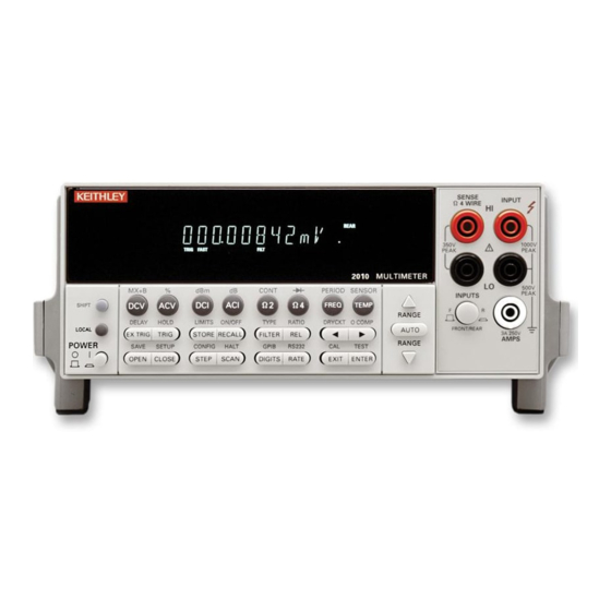
Operation Summary Power-on defaults Power-on defaults are those settings the instrument assumes when it is turned on. The Model 2010 offers two choices for the settings: user or factory. With user, the instrument will power-on to the settings stored in memory by the operator. - Page 14 Model 2010 SENSE INPUT Ω 4 WIRE Measure DCV, ACV, Ω2, FREQ (PERIOD) 350V 1100V PEAK PEAK or TC TEMP * 2000 MULTIMETER 500V PEAK INPUTS * Thermocouple (TC) Temperature RANGE measurements are typically AUTO FRONT/REAR 2A 250V AMPS RANGE...
- Page 15 Maximum inputs for the Model 2010 are summarized in Table 1. Table 1. Maximum inputs Function Maximum input 1000V peak 750V rms, 1000V peak, 8×10 V•Hz 3A, 250V dc 3A 250V rms FREQ (PERIOD) 1000V peak, 8×10 V•Hz Basic measurement procedure 1.
- Page 16 The RATE setting also sets bandwidth for ACU and ACI measurements. See the 2010 User’s Manual for details. DIGITS — Display resolution can be changed for any measurement function. Use the DIGITS key to select the...
- Page 17 FILTER — Filter state (on/off) and configuration can be changed for any measurement function, except fre- quency, period, continuity, and diode test. The FILTER key toggles between filter on (FILT annunciator on) and filter off. After pressing FILTER to enable the filter, you can then enter the filter count (1 to 100), and select the filter type (moving or repeating).
- Page 18 Math To enable and configure a math operation, press SHIFT and then the desired math key (MX+B, %, dBm, or dB). Use the , and keys to configure the math operation and press ENTER when finished. Pressing SHIFT and then the related math key a second time dis- ables the math operation.
-
Page 19: Measuring Continuity
Measuring continuity With this feature, the instrument alerts you with a beep when a resistance reading is below the set level. To measure continuity, press SHIFT and then CONT. Use , and keys to set the resistance threshold level, and press ENTER. Connect the test leads to INPUT HI and LO. - Page 20 Enabling limits — Press SHIFT and then ON/OFF to dis- play the beeper status. Use the keys to change the beeper status (NEVER, OUTSIDE, or INSIDE) and press ENTER to enable limits. Pressing SHIFT and then ON/OFF a second time disables limit operations. Reading hold With this feature, an audible beep is sounded when a valid, settled reading is acquired.
- Page 21 While in 2-wire or 4-wire ohms (Ω2 or Ω4), select offset compensation by pressing SHIFT and then O COMP. Ratio This feature lets you perform a ratio calculation between the sense input (denominator) and the measure input (numerator) for DC voltage. It lets you compare DC voltages (measure input) to a reference voltage (sense input).
- Page 22 AUTO or MANual. If MANual is chosen, enter the dura- tion of the delay and press ENTER. The AUTO delay times are listed in Table 3-2 of the Model 2010 User’s Manual. Scan operations The Model 2010 can be used with an internal scanner...
- Page 23 keys — These keys can be used to manually scan through channels on the internal scanner card. Press to manually increment channels or to man- ually decrement channels. Hold down either key to scan continuously. OPEN and CLOSE keys — Use these keys to open and close channels on the internal scanner card.
- Page 24 Factory default conditions Table 2. Factory defaults Setting Factory default Autozero Buffer No effect Continuity Beeper Digits Rate Fast (0.1 PLC) Threshold 10Ω Current (AC and DC) Digits (AC) Digits (DC) Filter Count Mode Moving average Range Auto Relative Value Rate (AC) Medium* Rate (DC)
- Page 25 Table 2. Factory defaults (cont.) Setting Factory default Percent Reference Resistance (2-wire and 4-wire) Digits Filter Count Mode Moving average Range Auto Relative Value Rate Medium (1 PLC) Dry Circuit Offset Compensation RS-232 Baud No effect Flow No effect Tx term No effect Scanning Channels...
- Page 26 Table 3. Error and status messages Number Description Event -440 Query unterminated after indefinite response -430 Query deadlocked -420 Query unterminated -410 Query interrupted -363 Input buffer overrun -350 Queue overflow -330 Self-test failed -314 Save/recall memory lost -315 Configuration memory lost Program syntax error -285 -284...
- Page 27 Table 3. Error and status messages (cont.) Number Description Event -148 Character data not allowed -144 Character data too long -141 Invalid character data -140 Character data error -128 Numeric data not allowed -124 Too many digits -123 Exponent too large -121 Invalid character in number -120...
- Page 28 Table 3. Error and status messages (cont.) Number Description Event Calibration messages: +400 10 vdc zero error +401 100 vdc zero error +402 10 vdc full scale error +403 -10 vdc full scale error +404 100 vdc full scale error +405 -100 vdc full scale error +406...
- Page 29 Table 3. Error and status messages (cont.) Number Description Event +465 750 vac full scale error +466 750 vac noise error +467 Post filter offset error +468 1 aac zero error +469 1 aac full scale error +470 3 aac zero error +471 3 aac full scale error +472...
- Page 30 DDC Calibration Locked +958 DDC Conflict Error +959 DDC No Remote Error +960 DDC Mode IDDC Error +961 DDC Mode IDDCO Error Keithley 199 Serial Poll Byte Events: +962 DDC Ready +963 DDC Reading Done +964 DDC Buffer Half Full +965...
-
Page 31: Remote Operation Summary
Remote Operation Summary At the factory, the instrument is set for GPIB bus opera- tion at primary address 16 using the SCPI programming language. GPIB bus — Use the GPIB bus configuration menu to enable or disable GPIB bus operation (ON or OFF), and to check and/or change the primary address (0 to 30) and language (SCPI or 196/199). - Page 32 Status structure Figure 2. Standard event status...
- Page 33 Figure 3. Operation event status...
- Page 34 Figure 4. Measurement event status...
- Page 35 Figure 5. Questionable event status...
- Page 36 Figure 6. Status byte and service request (SRQ)
- Page 37 Returns the Model 2010 *RCL <NRf> Recall command to the setup configura- tion stored in the speci- fied memory location. Returned the Model 2010 to the *RST default *RST Reset command conditions. Saves the current setup to *SAV <NRf> Save command the specified memory...
- Page 38 Request Enable Register. *STB? Read status byte query Reads the Status Byte Register. *TRG Trigger command Sends a bus trigger to the 2010. *TST? Self-test query Performs a checksum test on ROM and returns the result. *WAI Wait-to-continue com- Waits until all previous mand commands are executed.
- Page 39 3. Upper-case characters indicate the short-from ver- sion for each command word. Table 5. Signal oriented measurement commands Command Description :CONFigure:<function> Places the Model 2010 in a “one- shot” measurement mode for the spec- ified function. :FETCh? Requests the latest reading. :READ? Performs an :ABORt, :INITiate, and a :FETCh?.
- Page 40 Table 6. CALCulate command summary Default Command Description SCPI param. √ CALCulate[1] Subsystem to control CALC 1: √ :FORMat <name> Select math format (NONE, PERCent MXB, PERCent). √ :FORMat? Query math format. :KMATh Path to configure math calcula- tions: :MMFactor <NRf> Set “m”...
- Page 41 Table 6. CALCulate command summary (cont.) Default Command Description SCPI param. √ :CLEar Path to clear failed test: √ [:IMMediate] Clear failed test indication. √ :AUTO <b> Enable or disable auto clear. √ :AUTO? Query auto clear. √ :IMMediate Re-perform limit tests. √...
- Page 42 Table 8. FORMat command summary Default Command Description SCPI param. FORMat √ [:DATA]<type>[,<length>] Select data format: (ASCii, ASCii SREal, or DREal). √ [:DATA]? Query data format. :ELEMents <item list> Specify data elements: (READ- READing ing, CHANnel, and UNITs). :ELEMents? Query data elements. √...
- Page 43 Table 10. SENSe command summary Default Command Description SCPI param. [:SENSe[1]] √ :FUNCtion <name> Select measurement function: ‘VOLT ‘VOLTage:AC’, ‘VOLTage :DC’, [:DC]’ RESistance’, ‘FRESistance’, ‘CURRent:AC’, ‘CURRent: DC’ ,‘FREQuency’, ‘TEMPerature’, ‘PERiod’, ‘DIODe’, “CONTi- nuity’. √ :FUNCtion? Query function. √ :DATA? Return the last instrument reading.
- Page 44 Table 10. SENSe command summary (cont.) Default Command Description SCPI param. :COUNt? Query filter count. :STATe <b> Enable or disable filter. :STATe? Query state of digital filter. :DETector Path to configure bandwidth: :BANDwidth <NRf> Specify bandwidth (3 to 300e3). :BANDwidth? Query bandwidth.
- Page 45 Table 10. SENSe command summary (cont.) Default Command Description SCPI param. √ :REFerence <n> Specify reference (-757.5 to 757.5). √ :STATe <b> Enable or disable reference. √ :STATe? Query state of reference. :ACQuire Use input signal as reference. √ :REFerence? Query reference value.
- Page 46 Table 10. SENSe command summary (cont.) Default Command Description SCPI param. COUNt? Query filter count. :STATe <b> Enable or disable filter. :STATe? Query state of digital filter. :TERMinal <name> Select terminal type: (NORMal NORMal or SENSe). :TERMinal? Query terminal type. :RATio <b>...
- Page 47 Table 10. SENSe command summary (cont.) Default Command Description SCPI param. :DIGits? Query resolution. :AVERage Path to configure and control filter. :TCONtrol <name> Select filter type: (MOVing or (Note) REPeat). :TCONtrol? Query filter type. :COUNt <n> Specify filter count (1 to 100). :COUNt? Query filter count.
- Page 48 Table 10. SENSe command summary (cont.) Default Command Description SCPI param. √ :OCOMpensated <b> Enable or disable offset com- pensation. √ :OCOMpensated? Query offset compensation. :DCIRcuit <b> Enable or disable dry circuit ohms. :DCIRcuit? Query dry circuit ohms. :TEMPerature Path to configure temperature: :NPLCycles <n>...
- Page 49 Table 10. SENSe command summary (cont.) Default Command Description SCPI param. :TCOefficient <n> Specify temp coefficient 2e-4 (-0.09999 to 0.09999). :TCOefficient? Query temp coefficient. :OFFSET <n> Specify voltage offset at 0°C 5.463e-2 (-0.09999 to 0.09999). :OFFSet? Query voltage offset. :FRTD Path to configure FRTD sensor.
- Page 50 Table 10. SENSe command summary (cont.) Default Command Description SCPI param. :RANGe? Query threshold range. :REFerence <n> Specify reference (0 to 1). :STATe <b> Enable or disable reference. :STATe? Query state of reference. :ACQuire Use input signal as reference. :REFerence? Query reference value.
- Page 51 Table 11. STATus command summary (cont.) Default Command Description SCPI param. √ [:EVENt]? Read the event register. (Note 2) √ :ENABle <NRf> Program the enable register. (Note 3) √ :ENABle? Read the enable register. √ :CONDition? Read the condition register. √...
- Page 52 √ :STATe <b> Enable or disable beeper. √ :STATe? Query state of beeper. :LOCal Take 2010 out of remote and restore operation of front panel controls (RS-232 only). :REMote Place 2010 in remote (RS-232 only). :RWLock Lockout front panel controls (RS-232 only).
- Page 53 Table 14. Trigger command summary Default Command Description SCPI param. √ :INITiate Subsystem command path: √ [:IMMediate] Initiate one trigger cycle. √ :CONTinuous <b> Enable or disable continuous (Note 1) initiation. √ :CONTinuous? Query continuous initiation. √ :ABORt Reset trigger system. √...
- Page 54 Table 15. UNIT command summary Default Command Description SCPI param. :UNIT √ :TEMPerature <name> Select temperature measure- ment units (C, F, or K). √ :TEMPerature? Query temperature units. √ :VOLTage Path to configure voltage units. :AC <name> Select ACV measurement units (V, DB or DBM).
- Page 55 Table 16. Models 196/199 device-dependent command summary Mode Command Description Execute Execute other device-dependent commands. Function F0 DC volts AC volts 2-wire ohms DC current AC current ACV dB Not valid 2-wire offset compensation Temperature 4-wire ohms Frequency 4-wire offset compensation Range Ohms* ACV dB Freq...
- Page 56 Table 16. Models 196/199 device-dependent command summary (cont.) Mode Command Description Reading Readings from A/D converter mode Individual readings from data store All readings from data store (buffer dump) Data Disable data store store size Data store of n (n=1 to 500), fill and stop Interval Default interval, 175msec (SELECT OFF)
- Page 57 Table 16. Models 196/199 device-dependent command summary (cont.) Mode Command Description Status Send machine status word (199 for- mat only) Send error conditions (only supports no scanner, IDDC, IDDCO) Send Translator word list (since Trans- lator is not supported, replies with one space character) Send buffer size Send current value of “V”...
- Page 58 Table 16. Models 196/199 device-dependent command summary (cont.) Mode Command Description Scanning N11 Step mode, max channel is 2 Step mode, max channel is 3 Step mode, max channel is 4 Step mode, max channel is 5 Step mode, max channel is 6 Step mode, max channel is 7 Step mode, max channel is 8 Step mode, max channel is 9...
- Page 60 Specifications are subject to change without notice. All Keithley trademarks and trade names are the property of Keithley Instruments, Inc. All other trademarks and trade names are the property of their respective companies. Keithley Instruments, Inc. 28775 Aurora Road • Cleveland, Ohio 44139 • 440-248-0400 • Fax: 440-248-6168 1-888-KEITHLEY (534-8453) www.keithley.com...
Need help?
Do you have a question about the 2010 and is the answer not in the manual?
Questions and answers