Table of Contents
Advertisement
Quick Links
EP-BX6
EP-BX6
EP-BX6
EP-BX6
EP-BX6
A P entium
A P
A P
entium
entium
entium
A P
A P
entium
Slot1 Processor based AGP
Slot1 Processor based AGP
Slot1 Processor based AGP
Slot1 Processor based AGP
Slot1 Processor based AGP
mainboar
mainboar
mainboar d (100/66MHz)
mainboar
mainboar
TRADEMARK
All products and company names are trademarks or registered
trademarks of their respective holders.
These specifications are subject to change without notice.
II/III/Celer
II/III/Celer on
II/III/Celer
II/III/Celer
II/III/Celer
® ® ® ® ®
d (100/66MHz)
d (100/66MHz)
d (100/66MHz)
d (100/66MHz)
Manual Revision 1.0
October 15, 1999
on
on
on
on
Advertisement
Table of Contents

Related Manuals for EPOX EP-BX6


Summary of Contents for EPOX EP-BX6
- Page 1 EP-BX6 EP-BX6 EP-BX6 EP-BX6 EP-BX6 A P entium entium entium entium II/III/Celer II/III/Celer II/III/Celer on entium II/III/Celer II/III/Celer ® ® ® ® ® Slot1 Processor based AGP Slot1 Processor based AGP Slot1 Processor based AGP Slot1 Processor based AGP Slot1 Processor based AGP...
-
Page 2: User Notice
EPoX has been advised of the possibility of such damages arising from any defect or error in the manual or product. EPoX may revise this manual from time to time without notice. - Page 3 EP-BX6 serial number: _________________________________ Contacting Technical Support EPoX technical support is working hard to answer all of your questions online. From our website you can find answers to many common questions, drivers, BIOS updates, tech notes, and important technical bulletins. If you are still unable to locate the solution you are seeking, you always have the option to contact our support technicians directly.
-
Page 4: Table Of Contents
System Block Diagram ........1-7 Section 2 Features EP-BX6 Features ..........2-1 Section 3 Installatio EP-BX6 Detailed Layout ....... 3-2 Easy Installation Procedure Configure Settings .......... 3-3 System Memory Configuration ..... 3-6 ® Installing a Pentium II/III Processor .... 3-8 Device Connectors ......... - Page 5 EP-BX6 Sensor and CPU Speed Setting ...... 4-23 Change Supervisor or User Password ... 4-26 IDE HDD Auto Detection ......4-27 Save & Exit Setup ........... 4-29 Exit Without Saving ........4-29 Section 5 Appendix Appendix A Memory Map ..........A-1 I/O Map ............
- Page 6 EP-BX6 Page Left Blank...
-
Page 7: Introduction
Section 1 INTRODUCTION Components Checklist ü ü ü ü ü EP-BX6 mainboard ü ü ü ü ü EP-BX6 user’s manual ü ü ü ü ü Floppy ribbon cable ü ü ü ü ü D. (1) Hard driver ribbon cables ü ü ü ü ü... -
Page 8: Overview
Introduction EP-BX6 Overview Pentium II or Pentium III Processor ® ® ® ® ® The Pentium II or Pentium III Processor (The Pentium III Processor as 400/ 100MHz, 450/100MHz speed above with 512K-L2 cache Versions.) is the ® ® ®... -
Page 9: S.e.c. Cartridge Terminology
EP-BX6 Introduction ® ® The entire enclosed product is called the Pentium II or Pentium III Processor. The packaging technology and each of the physical elements of the product are referred to using accurate technical descriptions. This allows clear reference to the products as just a processor. -
Page 10: Accelerated Graphics Port
Introduction EP-BX6 The L2 cache (TagRAM, PBSRAM) components keep standard industry names. ® ® The Pentium II or Pentium III Processor is the first product to utilize the S.E.C. cartridge technology and Slot 1 connector. Unless otherwise noted, any refer- ®... -
Page 11: Ep-Bx6 Form-Factor
Introduction EP-BX6 Form-Factor The EP-BX6 is designed with ATX form factor - the new industry standard of chassis. The ATX form factor is essentially a Baby-AT baseboard rotated 90 degrees within the chassis enclosure and a new mounting configuration for the power supply. -
Page 12: I/O Shield Connector
Introduction EP-BX6 I/O Shield Connector The EP-BX6 is equipped with an I/O back panel. Please use the appropriate I/O shield (figure 3). Parallel Port PS/2 Mouse PS/2 Keyboard COM2 COM1 Figure 3: I/O back panel layout Power-On/Off (Remote) The EP-BX6 has a single 20-pin connector for ATX power supplies. For ATX power supplies that support the Remote On/Off feature, this should be connected to the systems front panel for system Power On/Off button. -
Page 13: System Block Diagram
EP-BX6 Introduction System Block Diagram P e n tium II or P e n tium III P roce ssor 100/66MHz 100/66MHz 66MHz PCI Bridge and memory controller 443BX PllX4E I/O Bridge Figure 5: System Block Diagram Page 1-7... - Page 14 Introduction EP-BX6 Page Left Blank Page 1-8...
-
Page 15: Features
Supports (1) 16 bit ISA slots, (6) 32 bit PCI slots, (1) AGP slot and provides (2) independent high performance PCI IDE interfaces capable of supporting PIO Mode 3/4 and Ultra DMA 33 devices. The EP-BX6 supports (6) PCI Bus Master slots and a jumperless PCI INT# control scheme which reduces configuration confusion when plugging in PCI card(s). - Page 16 Features EP-BX6 • EP-BX6 utilizes a Lithium battery which provides environmental protec tion and longer battery life. • Supports the Universal Serial Bus (USB) connector. The onboard PIIX4E chip provides the means for connecting PC peripherals such as; keyboards, joysticks, telephones, and modems.
- Page 17 Installation EP-BX6 Page 3-1...
-
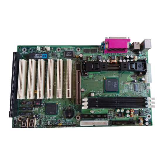
Page 18: Ep-Bx6 Detailed Layout
Installation EP-BX6 EP-BX6 Detailed Layout Figure 1 Page 3-2... -
Page 19: System Memory Configuration
Installation EP-BX6 The following must be completed before powering on your new system: 3-1. Configure Jumpers 3-2. System memory Configuration ® 3-3. Install Pentium II/III/Celeron Processor 3-4. Device Connectors 3-5. External Modem Ring-in Power ON and Keyboard Power ON Functions (KBPO) 3-6. - Page 20 Installation EP-BX6 I I I Note: Based on the implementation of the Intel 440BX AGPset, the EP-BX6 is able to provide multiple front side bus (FSB) frequencies for Slot 1 processors and memory operations. The mainboard's FSB is easily se- lected by BIOS Setup listed above to match the FSB required by your processor.
- Page 21 Installation EP-BX6 J P X 1 & J P X 2 J P X 1 T h e F ifth o r Six th P C I M a ster S elect & 1 -2 - S ix th S la v e (D efa u lt)
- Page 22 Installation EP-BX6 The EP-BX6 supports (3) 168-pin DIMMs (Dual In-line Memory Module). The DIMMs can be either EDO (Extended Data Out) or SDRAM (Synchronized DRAM). • We recommend not mixing SDRAM DIMM and EDO DIMM together. • EDO DIMM can only be used with the 66MHz FSB.
- Page 23 Installation EP-BX6 Figure 3 displays the notch marks and what they should look like on your DIMM memory module. DIMMs have 168-pins and two notches that will match with the onboard DIMM socket. DIMM modules are installed by placing the chip firmly into the socket at a 90 degree angle and pressing straight down (figure 4) until it fits tightly into the DIMM socket (figure 5).
- Page 24 Installation EP-BX6 ® The EP-BX6 uses the Single Edge Contact (SEC) slot for a Pentium II/III processor packaged in an SEC cartridge. The SEC slot is not compatible with ® other non-Pentium II/III processors. Please have ready the following list of components so that we may install the processor onto the motherboard.
- Page 25 Installation EP-BX6 cable will be shipped with the boxed processor to draw power from a power header on the mainboard’s J4. Now we are ready to install the SEC Cartridge (Pentium II/III Processor) into the Retention Module. The SEC Cartridge is mounted by sliding the SEC Cartridge into the Retention Module and letting it slide all the way down.
- Page 26 Installation EP-BX6 Please install the motherboard into the chassis. Now that your motherboard is installed you are ready to connect all your connec- tions (figure 7). Parallel Port PS/2 Mouse PS/2 Keyboard COM2 COM1 Figure 7 J2,J3: Chassis Panel Connector •...
- Page 27 Installation EP-BX6 Power On/Off (This is connected to the power button on the case. Using the Soft- Off by Pwr-BTTN feature, you can choose either Instant Off (turns system off immediatly), or 4 sec delay (you need to hold the button down for 4 seconds before the system turns off).
- Page 28 Installation EP-BX6 On the basis of bounded functions in I/O chipset, the two serial ports are able to support the External Modem Ring-in Power ON function. Once users connect the external modem to COM1 or COM2, the mainboard allows users to turn on their system through the remote and host's dial-up control.
- Page 29 Installation EP-BX6 Notes: 1. Intel ATX version 2.0 specification has recommended you use the power supply with 0.72A(720mA) in 5.0VSB. With our mainboard, the 5.0VSB standby power only has to be > = 0.1A (100mA) then you can enjoy this unique benefit.
- Page 30 Installation EP-BX6 The EP-BX6 supports the STR power management state by maintaining the appropriate states on the RDRAM interface signals. The power source must be kept alive to the RDRAM during STR (ACPI S3). Advanced Configuration Power Interface (ACPI) provides more Energy Saving Features for operating systems that support OS such as ON and QuickStart function.
- Page 31 Installation EP-BX6 c. It saves and keeps all on-screen data including any executed applications to DRAM. d. You must push the Power button connected with onboard J3 pin to wake up you system (not to click to mouse or press keyboard to wake up the system.)
- Page 32 Installation EP-BX6 Page 3-16...
-
Page 33: Standard Cmos Setup
EP-BX6 BIOS Award’s ROM BIOS provides a built-in Setup program which allows user to modify the basic system configuration and hardware parameters. The modified data will be stored in a battery-backed CMOS, so that data will be retained even when the power is turned off. In general, the information saved in the CMOS RAM will stay unchanged unless there is a configuration change in the system, such as hard drive replacement or a device is added. - Page 34 BIOS EP-BX6 The menu displays all the major selection items. Select the item you need to reconfigure. The selection is made by moving the cursor (press any direction key ) to the item and pressing the ‘Enter’ key. An on-line help message is displayed at the bottom of the screen as the cursor is moved to various items which provides a better understanding of each function.
- Page 35 Selecting the “BIOS FEATURES SETUP” option in the CMOS SETUP UTILITY menu allows users to change system related parameters in the displayed menu. This menu shows all of the manufacturer’s default values for the EP-BX6. Pressing the [F1] key will display a help message for the selected item.
- Page 36 BIOS EP-BX6 You should then run an anti-virus program to locate the virus. Keep in mind that this feature protects only the boot sector, not the entire hard drive. The default value is Disabled. Enabled: Activates automatically when the system boots up causing a warning message to appear when anything attempts to access the boot sector.
- Page 37 EP-BX6 BIOS Boot Sequence: This category determines which drive is searched first by the O/S (Operating System). The default is A,C,SCSI. The following is your list of options: [A, C, SCSI] - [C, A, SCSI] - [C, CD-ROM, A] - [CD-ROM, C, A]...
- Page 38 BIOS EP-BX6 15: 15 characters per second. 20: 20 characters per second. 24: 24 characters per second. 30: 30 characters per second. Typematic Delay (msec): This setting controls the time between the first and the second character displayed by typematic auto-repeat. The default is 250.
- Page 39 EP-BX6 BIOS Choose the “CHIPSET FEATURES SETUP” in the CMOS SETUP UTILITY menu to display following menu. ROM PCI/ISA BIOS(2A69KPAI) CHIPSET FEATURES SETUP AWARD SOFTWARE, INC. SDRAM RAS-to-CAS Delay SDRAM RAS Precharge Time SDRAM CAS Latency Time : Auto SDRAM Precharge Control...
- Page 40 BIOS EP-BX6 SDRAM CAS Latency Time: This setting defines the CAS timing parameter of the SDRAM in terms of clocks. The default is Auto. 2: Provides faster memory performance. 3: Provides better memory compatibility. Auto: CAS Latency Time programming depend on information read from DRAM SPD.
- Page 41 EP-BX6 BIOS 5: 5 wait states 6: 6 wait states 7: 7 wait states 16 Bit I/O Recovery Time: This function allows you to set the wait state that is added to an 16 bit ISA instruction originated by the PCI bus. The default is 1.
- Page 42 BIOS EP-BX6 Choose the “POWER MANAGEMENT SETUP” in the CMOS SETUP UTILITY to display the following screen. This menu allows the user to modify the power management parameters and IRQ signals. In general, these parameters should not be changed unless it’s absolutely necessary.
- Page 43 EP-BX6 BIOS Max. saving: Maximum power savings. Inactivity period is 1 minute in each mode. Min. saving: Minimum power savings. Inactivity period is 1 hour in each mode. User define: Allows user to define PM Timers parameters to control power saving mode.
- Page 44 BIOS EP-BX6 This Mainboard supports HDD Power Down, Doze and Standby power saving functions when using the Intel Pentium II Processor. The default is Disabled Doze Mode: The “Doze” mode timer starts to count when no “PM events” have occurred.
- Page 45 EP-BX6 BIOS PowerOn by Ring: This option is used to set the remote ring in feature. This option is only available when Power Loss Recovery is Enabled. The default is Enabled. Enabled: The system can use remote ring-in to wake the system up.
- Page 46 BIOS EP-BX6 The PNP/PCI configuration program is for the user to modify the PCI/ISA IRQ signals when various PCI/ISA cards are inserted in the PCI or ISA slots. WARNING: Conflicting IRQs may cause the system to not find certain devices.
- Page 47 EP-BX6 BIOS Reset Configuration Data: This setting allows you to clear ESCD data. The default is Disabled Disabled: Normal Setting. Enabled: If you have plugged in some Legacy cards to the system and they were recorded into ESCD (Extended System Configuration Data), you can set this field to Enabled in order to clear ESCD.
- Page 48 BIOS EP-BX6 The “LOAD SETUP DEFAULTS” function loads the system default data directly from ROM and initializes the associated hardware properly. This function will be necessary only when the system CMOS data is corrupted. ROM PCI/ISA BIOS(2A69KPAI) INTEGRATED PERIPHERALS AWARD SOFTWARE, INC.
- Page 49 EP-BX6 BIOS IDE Primary Master PIO: The default is Auto. Auto: BIOS will automatically detect the Onboard Primary Master PCI IDE HDD Accessing mode. Mode 0~4: Manually set the IDE Programmed interrupt mode. IDE Primary Slave PIO: The default is Auto.
- Page 50 BIOS EP-BX6 On-Chip Primary PCI IDE: This option turns on/off the onboard primary IDE. The default is Enabled. Enabled: This activates the primary PCI IDE. Disabled: This disable sthe primary PCI IDE and frees up the resource. On-Chip Secondary PCI IDE: This option turns on/off the onboard secondary IDE.
- Page 51 EP-BX6 BIOS Hot Key Power On: Use this option with the above “Power On Function” to set a combination of keys that can be used to power the system on. The default is Ctrl-F1. Options: Ctrl-F1, Ctrl-F2, Ctrl-F3, Ctrl-F4, Ctrl-F5, Ctrl-F6, Ctrl-F7, Ctrl- F8, Ctrl-F9, Ctrl-F10, Ctrl-F11, and Ctrl-F12.
- Page 52 BIOS EP-BX6 IR Transmission delay: This default is Enabled (when UART Mode Select is not set to Normal). Options: Enabled and Disabled Onboard Parallel port: This field allows the user to configure the LPT port. The default is 378H / IRQ7.
-
Page 53: Sensor And Cpu Speed Setting
EP-BX6 BIOS Choose the “SENSOR & CPU SPEED SETTING” in the CMOS SETUP UTILITY to display the following screen. This menu allows to choose the correct CPU speed to match your CPU installed. ROM PCI/ISA BIOS(2A69KPAI) SENSOR & CPU SPEED SETTING AWARD SOFTWARE, INC. - Page 54 BIOS EP-BX6 CPU/AGP Clk Ratio: The default is Default. Default: If the CPU host bus selects above 83.3Mhz, AGP will run clock at 2/3 CPU’s If the CPU host bus selects less or equal to 83.3MHz, AGP will run clock same as CPU’s.
- Page 55 EP-BX6 BIOS Shutdown Temperature: This is the temperature that the computer will turn off the power to combat the effects of an overheating system. (requires ACPI to be enabled in Power Management BIOS and ACPI compliant operating system.) The default is 100 C/167 To change the password, choose the “SUPERVISOR PASSWORD or USER...
-
Page 56: Ide Hdd Auto Detection
BIOS EP-BX6 The “IDE HDD auto detection” utility is a very useful tool, especially when you do not know which kind of hard disk type you are using. You can use this utility to detect the correct disk type installed in the system automatically. But now you can set HARD DISK TYPE to Auto in the STANDARD CMOS SETUP. - Page 57 EP-BX6 BIOS If user set his HDD to NORMAL mode, the maximum accessible HDD size will be 528 Megabytes even though its physical size may be greater than that! LBA (Logical Block Addressing) mode: A new HDD accessing method to overcome the 528 Megabyte bottleneck.
-
Page 58: Save & Exit Setup
BIOS EP-BX6 Note: To support LBA or LARGE mode of HDDs, there must be some software involved. All the software is located in the Award HDD Service Routine (INT 13h). It may fail to access a HDD with LBA (LARGE) mode selected if you are running under an Operating System which replaces the whole INT 13h. -
Page 59: Memory Map
EP-BX6 Appendix Appendix A A-1 MEMORY MAP Address Range Size Description [00000-7FFFF] 512K Conventional memory [80000-9FBFF] 127K Extended Conventional memory [9FC00-9FFFF] Extended BIOS data area if PS/2 mouse is installed [A0000-C7FFF] 160K Available for Hi DOS memory [C8000-DFFFF] Available for Hi DOS memory and adapter... -
Page 60: Timer & Dma Channels Map
EP-BX6 Appendix [2F8-2FF] SERIAL port 2. [360-36F] NETWORK ports. [378-37F] PARALLEL port 1. [3B0-3BF] MONOCHROME & PARALLEL port adapter. [3C0-3CF] EGA adapter. [3D0-3DF] CGA adapter. [3F0-3F7] FLOPPY DISK controller. [3F8-3FF] SERIAL port 1. A-3 TIMER & DMA CHANNELS MAP TIMER MAP: TIMER Channel 0 System timer interrupt. -
Page 61: Rtc & Cmos Ram Map
EP-BX6 Appendix FLOPPY DISK (SMC CHIP). PARALLEL port 1. RTC clock. Available. Available. Available. PS/2 Mouse. MATH coprocessor. Onboard HARD DISK (IDE1) channel. Onboard HARD DISK (IDE1) channel. A-5 RTC & CMOS RAM MAP RTC & CMOS: Seconds. Second alarm. - Page 62 EP-BX6 Appendix Base memory high byte. Extension memory low byte. Extension memory high byte. 19-2d 2E-2F Reserved for extension memory low byte. Reserved for extension memory high byte. DATE CENTURY byte. INFORMATION FLAG. 34-3F Reserve. 40-7F Reserved for CHIPSET SETTING DATA.
-
Page 63: Post Codes
EP-BX6 Appendix Appendix B B-1 POST CODES ISA POST codes are typically output to I/O port address 80h. POST (hex) DESCRIPTION 01-02 Reserved. Turn off OEM specific cache, shadow. 1. Initialize EISA registers (EISA BIOS only). 2. Initialize all the standard devices with default values Standard devices includes. - Page 64 EP-BX6 Appendix Create resource map from ESCD. 5. Assign IO & Memory for PCI devices. (PCI BIOS only) Initialization of the BIOS Data Area. (40:ON - 40:FF) 1. Program some of the Chipset's value according to Setup. (Early Setup Value Program) 2.
- Page 65 EP-BX6 Appendix 2. Program all onboard super I/O chips (if any) including COM ports, LPT ports, FDD port ... according to setup value. 33-3B Reserved. Set flag to allow users to enter CMOS Setup Utility. 1. Initialize Keyboard. 2. Install PS2 mouse.
-
Page 66: Unexpected Errors
EP-BX6 Appendix 6. Power Management Initialization. Enable/Disable global PM. APM interface initialization. 1. If it is NOT a PnP BIOS, initialize serial & parallel ports. 2. Initialize time value in BIOS data area by translate the RTC time value into a timer tick value. -
Page 67: Load Setup Defaults
EP-BX6 Appendix Appendix C NOTE: The "LOAD SETUP DEFAULTS" function loads the system default data directly from ROM and initializes the associated hardware properly. This function will be necessary when you accept this mainboard, or the system CMOS data is corrupted. - Page 68 EP-BX6 Appendix Page Left Blank A-10...
-
Page 69: Ghost 5.1 Quick User's Guide
EP-BX6 Appendix Appendix D D-1 GHOST 5.1 Quick User’s Guide Installation is very easy. You only need to copy the Ghost5 folder or Ghost.exe to your hard disk. The current market version is for single Client, so the LPT and NetBios portions will not be explained further. - Page 70 Appendix EP-BX6 There are 3 hard disk functions: 1. Disk To Disk (disk cloning) 2. Disk To Image (disk backup) 3. Disk From Image (restore backup) Important! 1. To use this function, the system must have at least 2 disks. Press the Tab key to move the cursor.
- Page 71 EP-BX6 Appendix 4. Click OK to display the following confirmation screen. Select Yes to start. Disk To Image (Disk Backup) 1. Select the location of the Source drive. 2. Select the location for storing the backup file. A-13...
- Page 72 Appendix EP-BX6 3. Click OK to display the following confirmation screen. Select Yes to start. Disk From Image (Restore Backup) 1. Select the Restore file. 2. Select the Destination drive of the disk to be restored. A-14...
- Page 73 EP-BX6 Appendix 3. When restoring disk backup, set the required partition size as shown in the following figure. 4. Click OK to display the following confirmation screen. Select Yes to start. Partition A-15...
- Page 74 Appendix EP-BX6 There are 3 partition functions: 1. Partition To Partition (partition cloning) 2. Partition To Image (partition backup) 3. Partition From Image (restore partition) Partition To Partition (Partition Cloning) The basic unit for partition cloning is a partition. Refer to disk cloning for the operation method.
- Page 75 EP-BX6 Appendix 3. Select the path and file name for storing the backup file. 4. Is the file compressed? There are 3 options: (1) No: do not compress data during backup (2) Fast: Small volume compression (3) High: high ratio compression. File can be compressed to its minimum, but this requires longer execution time.
- Page 76 Appendix EP-BX6 Partition From Image (Restore Partition) Select the backup file to be restored. 2. Select the source partition. 3. Select the disk to be restored. A-18...
- Page 77 EP-BX6 Appendix 4. Select the partition to be restored. 5. Select Yes to start restoring. Check This function checks the hard disk or backup file for backup or restoration error due to FAT or track error. A-19...
Need help?
Do you have a question about the EP-BX6 and is the answer not in the manual?
Questions and answers