Table of Contents
Advertisement
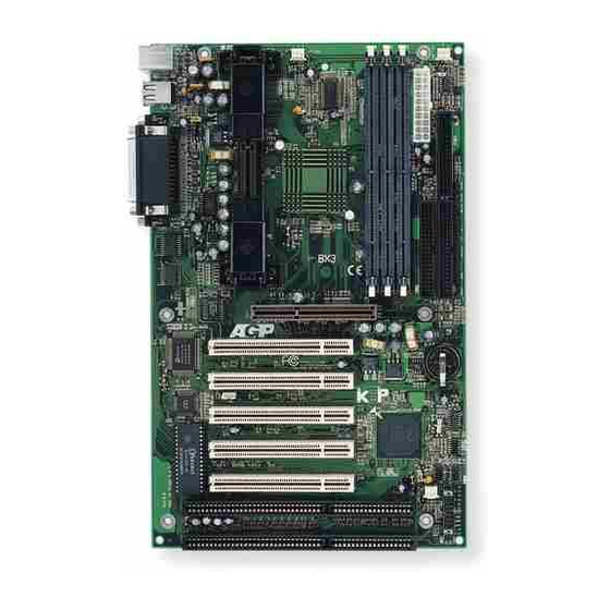
EP-BX3
EP-BX3
EP-BX3
EP-BX3
EP-BX3
A Pentium
A Pentium
A Pentium
A Pentium
A Pentium
Slot1 Processor based AGP
Slot1 Processor based AGP
Slot1 Processor based AGP
Slot1 Processor based AGP
Slot1 Processor based AGP
mainboard (100/66MHz)
mainboard (100/66MHz)
mainboard (100/66MHz)
mainboard (100/66MHz)
mainboard (100/66MHz)
TRADEMARK
All products and company names are trademarks or
registered trademarks of their respective holders.
These specifications are subject to change without
notice.
II or Deschutes
II or Deschutes
II or Deschutes
II or Deschutes
II or Deschutes
® ® ® ® ®
Manual Revision 1.0
November 18, 1998
Advertisement
Table of Contents

Related Manuals for EPOX EP-BX3


Summary of Contents for EPOX EP-BX3
- Page 1 EP-BX3 EP-BX3 EP-BX3 EP-BX3 EP-BX3 A Pentium A Pentium A Pentium II or Deschutes II or Deschutes II or Deschutes A Pentium A Pentium II or Deschutes II or Deschutes ® ® ® ® ® Slot1 Processor based AGP Slot1 Processor based AGP...
- Page 2 EP-BX3...
-
Page 3: Bios Upgrades
If your retailer can not help, you may E-Mail us with any questions at the following address tech@epox.com Record your serial number before installing your EP-BX3 mainboard. (the serial number is located near the ISA slots at the edge of the board) -
Page 4: User Notice
In no event shall EPoX be liable for any loss or profits, loss of business, loss of use or data, interruption of business or for... -
Page 5: Table Of Contents
System Block Diagram ........1-8 Section 2 Features EP-BX3 Features ........... 2-1 Section 3 Installation EP-BX3 Detailed Layout ........ 3-2 Easy Installation Procedure Configure Jumpers .......... 3-3 System Memory Configuration ......3-5 ® Installing a Pentium II Processor ....3-9 Device Connectors ......... - Page 6 EP-BX3 Power Management Setup ......4-12 PNP/PCI Configuration ........4-16 Load Setup Defaults ........4-18 Integrated Peripherals ........4-18 Change Supervisor or User Password ..... 4-23 IDE HDD Auto Detection ....... 4-24 HDD Low Level Format ......... 4-26 Save & Exit Setup .......... 4-26 Exit Without Saving .........
-
Page 7: Introduction
INTRODUCTION Components Checklist ü ü ü ü ü EP-BX3 mainboard ü ü ü ü ü EP-BX3 user’s manual ü ü ü ü ü Floppy ribbon cable ü ü ü ü ü Hard drive ribbon cables ü ü ü ü ü... -
Page 8: Overview
Introduction EP-BX3 Overview Pentium II or Deschutes Processor ® The Pentium II or Deschutes Processor (The Deschutes Processor as 300/ 100MHz, 350/100MHz, 400/100MHz and 450/100MHz speed with 512K-L2 cache ® ® Versions.) is the follow-on to the Pentium Processor. The Pentium II or ®... -
Page 9: Cartridge Terminology
EP-BX3 Introduction packaging technology and each of the physical elements of the product are referred to using accurate technical descriptions. This allows clear reference to the products as just a processor. This is the model used in past packaging technologies like PGA, TCP, PQFP, DIP, etc. -
Page 10: Accelerated Graphics Port
Introduction EP-BX3 ® “Pentium II or Deschutes Processor/Slot 1 processor” or “Deschutes Processor” ® will apply to both the Pentium II Processor desktop processors. Accelerated Graphics Port (AGP or A.G.P.) Typically, 3D graphics rendering requires a tremendous amount of memory, and demands ever increasing throughput speed as well. - Page 11 EP-BX3 Introduction Page Right Blank Page 1-5...
-
Page 12: Ep-Bx3 Form-Factor
EP-BX3 EP-BX3 Form-Factor The EP-BX3 is designed with ATX form factor - the latest industry standard of chassis. The ATX form factor is essentially a Baby-AT baseboard rotated 90 degrees within the chassis enclosure and a new mounting configuration for the power supply. -
Page 13: I/O Shield Connector
EP-BX3 Introduction I/O Shield Connector The EP-BX3 is equipped with an I/O back panel. Please use the appropriate I/O shield (figure 3). Parallel Port Figure 3: PS/2 Mouse EP-BX3 I/O back PS/2 Keyboard panel layout COM2 COM1 Power-On/Off (Remote) The EP-BX3 has a single 20-pin connector for ATX power supplies. For ATX power supplies that support the Remote On/Off feature, this should be connected to the systems front panel for system Power On/Off button. -
Page 14: System Block Diagram
Introduction EP-BX3 System Block Diagram P e n tiu m II or D e sch utes P ro ce ssor 1 0 0 /6 6 M Hz 1 0 0 /6 6 M Hz 6 6 M Hz PCI Bridge... -
Page 15: Features
Supports (2) 16 bit ISA slots, (5) 32 bit PCI slots, (1) AGP slot and provides (2) independent high performance PCI IDE interfaces capable of supporting PIO Mode 3/4 and Ultra DMA 33 devices. The EP-BX3 supports (5) PCI Bus Master slots and a jumperless PCI INT# control scheme which reduces configuration confusion when plugging in PCI card(s). - Page 16 Features EP-BX3 • EP-BX3 utilizes a Lithium battery which provides environmental protection and longer battery life. • Supports the Universal Serial Bus (USB) connector. The onboard PIIX4E chip provides the means for connecting PC peripherals such as; keyboards, joysticks, telephones, and modems.
- Page 17 EP-BX3 Installation Page 3-1...
-
Page 18: Ep-Bx3 Detailed Layout
Installation EP-BX3 EP-BX3 Detailed Layout Figure 1 Page 3-2... -
Page 19: Configure Jumpers
EP-BX3 Installation The following must be completed before powering on your new system: 3-1. Configure Jumpers to match your hardware 3-2. Install memory chips 3-3. Install Pentium II or Deschutes Processor 3-4. Device Connectors We design this mainboard with the an ESDJ to make your install fast and easy. - Page 20 Installation EP-BX3 Note: Based on the implementation of Intel 440BX PCIset, EP-BX3 is able to provide two host bus frequencies -- either 66 or 100MHz for Slot1 processor and memory operating. The default is set at 100MHz once Pentium II processor to ®...
- Page 21 EP-BX3 Installation The EP-BX3 supports (3) 168-pin DIMMs (Dual In-line Memory Module). The DIMMs can be either EDO (Extended Data Out) or SDRAM (Synchronized DRAM). The DIMMs may be installed using just one chip. • We recommend using SDRAM DIMM can not mixing with EDO DIMM modules.
- Page 22 Installation EP-BX3 Table 1 * SDRAM only supports 8, 16, 32, 64, 128MB DIMM modules. 256MB only supports Registered Synchronouts DRAM Memory Modules. ® * EDO only supports Pentium II Processor at 66MHz, not supports Deschutes Processor at 100MHz. Figure 3 displays the notch marks and what they should look like on your DIMM memory module.
- Page 23 EP-BX3 Installation Figure 6 DIMM Module clip before installation Figure 7 DIMM Module clip after installation To remove the DIMM module simply press down both of the white clips on either side and the module will be released from the socket.
- Page 24 Installation EP-BX3 The EP-BX3 uses the Single Edge Contact (SEC) slot for a Pentium II processor packaged in an SEC cartridge. The SEC slot is not compatible with other non- Pentium II processors. Please have ready the following list of components so that we may install the proces- sor onto the motherboard.
- Page 25 EP-BX3 Installation bottom make sure you press firmly on SEC cartridge to firmly secure into the Slot 1 Socket. Now we need to secure the heatsink with the top half of the support (figure 11). Take the top piece of the support and slide it into the bottom fin (figure 11) on the heatsink and then push forward until it clips into the bottom base (figure 9) that is already there (figure 11).
- Page 26 Installation EP-BX3 Please install the motherboard into the chassis. Now that your motherboard is installed you are ready to connect all your connections (figure 12). 1 2 3 4 5 6 7 8 9 0 1 2 3 4 5 6 7 8 9 0 1 2 3 4 5 6 7 8 9 0 1 2 1 2 3 4 5 6 7 8 9 0 1 2 3 4 5 6 7 8 9 0 1 2 3 4 5 6 7 8 9 0 1 2 1 2 3 4 5 6 7 8 9 0 1 2 3 4 5 6 7 8 9 0 1 2 3 4 5...
- Page 27 EP-BX3 Installation Reset - Closed to restart system. Speaker - Connect to the system's speaker for beeping 1. Speaker 3. GND 2. N/C 4. GND KeyLock - Keyboard lock switch & Power LED connector 1. Power LED(+) 4. Keylock 2. N/C 5.
-
Page 28: Keyboard Power On Function (Kbpo)
On the basis of bounded functions in I/O chipset, the two serial ports are able to support the External Modem Ring-in Power ON function. Once users connect the external modem to COM1 or COM2, the EP-BX3 mainboard allows users to turn on their system through the remote and host's dial-up control. - Page 29 Notes: 1.Intel ATX version 2.0 specification has recommended you use the power supply with 0.72A(720mA) in 5.0VSB. With our EP-BX3 mainboard, the 5.0VSB standby power only has to be > = 0.1A (100mA) then you can enjoy this unique benefit. However, the ATX power supply which is < 0.1 (100mA) is still applicable to your system by placed JP13 at the position 2-3 to disable this feature.
- Page 30 Installation EP-BX3 Page 3-14...
-
Page 31: Standard Cmos Setup
EP-BX3 BIOS Award’s ROM BIOS provides a built-in Setup program which allows user to modify the basic system configuration and hardware parameters. The modified data will be stored in a battery-backed CMOS, so that data will be retained even when the power is turned off. - Page 32 BIOS EP-BX3 The menu displays all the major selection items. Select the item you need to reconfigure. The selection is made by moving the cursor (press any direction key ) to the item and pressing the ‘Enter’ key. An on-line help message is displayed at the bottom of the screen as the cursor is moved to various items which provides a better understanding of each function.
- Page 33 Selecting the “BIOS FEATURES SETUP” option in the CMOS SETUP UTILITY menu allows users to change system related parameters in the displayed menu. This menu shows all of the manufacturer’s default values for the EP-BX3. Pressing the [F1] key will display a help message for the selected item.
- Page 34 BIOS EP-BX3 Enabled: Activates automatically when the system boots up causing a warning message to appear when anything attempts to access the boot sector. Disabled: No warning message will appear when anything attempts to access the boot sector. Note: Many disk diagnostic programs that access the boot sector table can trigger the virus warning message.
- Page 35 EP-BX3 BIOS Swap Floppy Drive: This will swap your physical drive letters A & B if you are using two floppy disks. The default is Disabled. Enabled: Floppy A & B will be swapped under the O/S. Disabled: Floppy A & B will be not swapped.
- Page 36 BIOS EP-BX3 Typematic Rate Setting: This determines the keystrokes repeat rate. The default is Disabled. Enabled: Allows typematic rate and typematic delay programming. Disabled: The typematic rate and typematic delay will be controlled by the keyboard controller in your system.
- Page 37 EP-BX3 BIOS Assign IRQ For VGA: This option allows BIOS to assign IRQ for VGA device Enabled: The system was assigned IRQ for VGA Card. Disabled: The system was not assigned IRQ for VGA Card. OS Select For DRAM > 64MB: Some operating systems require special handling.
- Page 38 BIOS EP-BX3 Choose the “CHIPSET FEATURES SETUP” in the CMOS SETUP UTILITY menu to display following menu. ROM PCI/ISA BIOS(2A69KPAB) CHIPSET FEATURES SETUP AWARD SOFTWARE, INC. Auto Configuration : Enabled Auto Detect DIMM/PCI Clk : Enabled EDO DRAM Timing : 60ns...
- Page 39 EP-BX3 BIOS 50ns: (Faster) Burst Wait State, for 50ns EDO DRAM. 60ns: (Slower) Burst Wait State, for 60ns Fast Page Mode/EDO DRAM. EDO CASx# MA Wait State: This allows the option to insert an additional wait state before the assertion of the first CASx# for page hit cycle.
- Page 40 BIOS EP-BX3 Video RAM Cacheable: This option allows the CPU to cache read/writes of the video RAM. The default is Enabled. Enabled: This option allows for faster video access. Disabled: Reduced video performance. 8 Bit I/O Recovery Time: This function allows you to set the wait state that is added to an 8 bit ISA instruction originated by the PCI bus.
- Page 41 EP-BX3 BIOS Delayed Transaction: This option allows the chipset to use its embedded 32-bit posted write buffer to support delay transactions cycles. The default is Disabled. Enabled: Select enabled to support PCI 2.1 specification. Disabled: Disabled. AGP Aperture Size: The amount of system memory that the AGP card is allowed to share.
- Page 42 BIOS EP-BX3 CPU Warning Temperature: This is the temperature that the computer will respond to an overheating CPU. The default is Disabled. Enabled: Temperature is monitored on the CPU Disabled: This feature is turned off. Current CPU Temperature: This is the current temperature of the CPU.
- Page 43 EP-BX3 BIOS You can only change the content of Doze Mode, Standby Mode, and Suspend Mode when the Power Management is set to ‘User Define’. Power Management: Use this to select your Power Management selection. The default is User define.
- Page 44 9: IRQ 9 10: IRQ 10 11: IRQ 11 The EP-BX3 supports HDD Power Down, Doze and Standby power saving func- tions when using the Intel Pentium II Processor. The default is Disabled Doze Mode: The “Doze” mode timer starts to count when no “PM events” have occurred.
- Page 45 EP-BX3 BIOS Resume by Ring: This option is used to set the remote ring in feature. This option is only available when Power Loss Recovery is Enabled. The default is Enabled. Enabled: The system can use remote ring-in to wake the system up.
- Page 46 BIOS EP-BX3 The PNP/PCI configuration program is for the user to modify the PCI/ISA IRQ signals when various PCI/ISA cards are inserted in the PCI or ISA slots. WARNING: Conflicting IRQ’s may cause the system to not find certain devices.
- Page 47 EP-BX3 BIOS Disabled: Normal Setting. Enabled: If you have plugged in some Legacy cards to the system and they were recorded into ESCD (Extended System Configuration Data), you can set this field to Enabled in order to clear ESCD. PCI IDE IRQ Map To: This item allows the user to configure the system for the type of IDE hard disk controller in use.
- Page 48 BIOS EP-BX3 The default is Enabled. Enalbed: Provides IRQ for USB device. Disabled: Release IRQ for other device. The “LOAD SETUP DEFAULTS” function loads the system default data directly from ROM and initializes the associated hardware properly. This function will be necessary only when the system CMOS data is corrupted.
- Page 49 EP-BX3 BIOS IDE HDD Block Mode: IDE Block Mode allows the controller to access blocks of sectors rather than a single sector at a time. The default is Enabled. Enabled: Enabled IDE HDD Block Mode. Provides higher HDD transfer rates.
- Page 50 BIOS EP-BX3 Mode 0~4: Manually set the IDE Programmed interrupt mode. IDE Primary Master UDMA: This allows you to select the mode of operation for the hard drive. The default is Auto. Auto: The computer will select the optimal setting.
- Page 51 EP-BX3 BIOS OnBoard Secondary PCI IDE: This option turns on/off the onboard secondary IDE. The default is enabled. Enabled: This activates the secondary PCI IDE. Disabled: This disables the secondary PCI IDE and frees up its resources. KBC input clock: This sets the keyboard clock value.
- Page 52 BIOS EP-BX3 UART Mode Select: The mode of the IR Controller. The default is Normal. IrDA: Support a Serial Infrared Inferface IrDA. ASKIR: Support a Sharp Serial Infrared Interface formats. Normal: The IRRX and IRTX pins of IR function in normal condition.
- Page 53 EP-BX3 BIOS On Button to power on the system. Password: User can Power On the System by password, the password can be entered from 1 to 5 characters. The maximum of password is 5 characters. If user forget / lost the password, please go into BIOS setting to change the Power On Method, or keyin another words as password instead of original one.
- Page 54 BIOS EP-BX3 The “IDE HDD auto detection” utility is a very useful tool, especially when you do not know which kind of hard disk type you are using. You can use this utility to detect the correct disk type installed in the system automatically. But now you can set HARD DISK TYPE to Auto in the STANDARD CMOS SETUP.
- Page 55 EP-BX3 BIOS If user set his HDD to NORMAL mode, the maximum accessible HDD size will be 528 Megabytes even though its physical size may be greater than that! LBA (Logical Block Addressing) mode: A new HDD accessing method to overcome the 528 Megabyte bottleneck.
- Page 56 BIOS EP-BX3 Note: To support LBA or LARGE mode of HDDs, there must be some software involved. All the software is located in the Award HDD Service Routine (INT 13h). It may fail to access a HDD with LBA (LARGE) mode selected if you are running under an Operating System which replaces the whole INT 13h.
-
Page 57: Appendix
EP-BX3 Appendix Appendix A: A-1 MEMORY MAP Address Range Size Description [00000-7FFFF] 512K Conventional memory [80000-9FBFF] 127K Extended Conventional memory [9FC00-9FFFF] Extended BIOS data area if PS/2 mouse is installed [A0000-C7FFF] 160K Available for Hi DOS memory [C8000-DFFFF] Available for Hi DOS memory and adapter ROMs... -
Page 58: Timer & Dma Channels Map
Appendix EP-BX3 [3D0-3DF] CGA adapter. [3F0-3F7] FLOPPY DISK controller. [3F8-3FF] SERIAL port 1. A-3 TIMER & DMA CHANNELS MAP TIMER MAP: TIMER Channel 0 System timer interrupt. TIMER Channel 1 DRAM REFRESH request. TIMER Channel 2 SPEAKER tone generator. DMA CHANNELS: DMA Channel 0 Available. -
Page 59: Rtc & Cmos Ram Map
EP-BX3 Appendix Onboard HARD DISK (IDE1) channel. Onboard HARD DISK (IDE1) channel. A-5 RTC & CMOS RAM MAP RTC & CMOS: Seconds. Second alarm. Minutes. Minutes alarm. Hours. Hours alarm. Day of week. Day of month. Month. Year. Status register A. - Page 60 Appendix EP-BX3 Page Left Blank...
-
Page 61: Post Codes
EP-BX3 Appendix Appendix B: B-1 POST CODES ISA POST codes are typically output to I/O port address 80h. POST (hex) DESCRIPTION 01-02 Reserved. Turn off OEM specific cache, shadow. 1. Initialize EISA registers (EISA BIOS only). 2. Initialize all the standard devices with default values Standard devices includes. - Page 62 Appendix EP-BX3 Initialization of the BIOS Data Area. (40:ON - 40:FF) 1. Program some of the Chipset's value according to Setup. (Early Setup Value Program) 2. Measure CPU speed for display & decide the system clock speed. 3. Video initialization including Monochrome, CGA, EGA/VGA. If no display device found, the speaker will beep.
- Page 63 EP-BX3 Appendix Try to turn on Level 2 cache. Note: Some chipset may need to turn on the L2 cache in this stage. But usually, the cache is turn on later in POST 61h. 3F-40 Reserved. 1. Program the rest of the Chipset's value according to Setup.
-
Page 64: Unexpected Errors
Appendix EP-BX3 1. Try to turn on Level 2 cache. Note: If L2 cache is already turned on in POST 3D, this part will be skipped. 2. Set the boot up speed according to Setup setting. 3. Last chance for Chipset initialization. -
Page 65: Load Setup Defaults
EP-BX3 Appendix Appendix C NOTE: The "LOAD SETUP DEFAULTS" function loads the system default data directly from ROM and initializes the associated hardware properly. This function will be necessary when you accept this mainboard, or the system CMOS data is corrupted. -
Page 66: Cpu Clock Frequency Selection In Bios Setting
Appendix EP-BX3 Appendix D CPU Clock Frequency Selection In BIOS Setting. There is a special function for CPU over-clocking requirement which can be chosen and set by BIOS, please refer to the following steps for adjustment. 1. Enter the BIOS CMOS setup program.
Need help?
Do you have a question about the EP-BX3 and is the answer not in the manual?
Questions and answers