Table of Contents
Advertisement
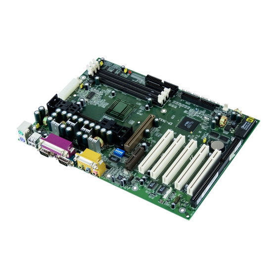
EP-7KXA
EP-7KXA
EP-7KXA
EP-7KXA
EP-7KXA
An AMD Athlon Slot A Processor
An AMD Athlon Slot A Processor
An AMD Athlon Slot A Processor
An AMD Athlon Slot A Processor
An AMD Athlon Slot A Processor
based mainboar
based mainboar
based mainboar d (133/100MHz)
based mainboar
based mainboar
Suppor
Suppor
ts PC-133 SDRAM Modules
ts PC-133 SDRAM Modules
Suppor
Suppor ts PC-133 SDRAM Modules
Suppor
ts PC-133 SDRAM Modules
ts PC-133 SDRAM Modules
TRADEMARK
These specifications are subject to change without notice.
d (133/100MHz)
d (133/100MHz)
d (133/100MHz)
d (133/100MHz)
Manual Revision 3.1
January 28, 2000
Advertisement
Table of Contents

Subscribe to Our Youtube Channel
Related Manuals for EPOX EP-7KXA


Summary of Contents for EPOX EP-7KXA
- Page 1 EP-7KXA EP-7KXA EP-7KXA EP-7KXA EP-7KXA An AMD Athlon Slot A Processor An AMD Athlon Slot A Processor An AMD Athlon Slot A Processor An AMD Athlon Slot A Processor An AMD Athlon Slot A Processor based mainboar based mainboar based mainboar d (133/100MHz)
- Page 2 EP-7KXA Table of Contents Page Section 1 Introduction Overview Section 2 Features Section 3 Installatio Easy Installation Procedure Section 4 Award BIOS Setup...
- Page 3 EP-7KXA Appendix Appendix A Appendix B Appendix C Appendix D...
- Page 4 EP-7KXA Page Left Blank...
-
Page 5: Components Checklist
EP-7KXA Introduction Section 1 INTRODUCTION Components Checklist USER’S MANUAL EP-7KXA Page 1-1... - Page 6 Introduction EP-7KXA Overview AMD Athlon Processor Page 1-2...
- Page 7 EP-7KXA Introduction S.E.C. Cartridge Terminology Figure 1: AMD Athlon Processor with S.E.C.C. Page 1-3...
-
Page 8: Hardware Monitoring
Introduction EP-7KXA Accelerated Graphics Port (AGP or A.G.P.) Hardware Monitoring Page 1-4... - Page 9 EP-7KXA Introduction EP-7KXA Form-Factor Power Supply 3 1/2" 5 1/4" Figure 2: Summary of ATX chassis features Page 1-5...
-
Page 10: Power-On/Off (Remote)
Introduction EP-7KXA I/O Shield Connector The EP-7KXA Joystick/Midi parallel port PS/2 Mouse USB port PS/2 KEYBOARD COM1 COM2 Speaker Line_in Figure 3: I/O back panel layout Power-On/Off (Remote) The EP-7KXA Remote On/Off The EP-7KXA POWER SUPPLY Case (chassis) Power ON/OFF button (J 3) -
Page 11: System Block Diagram
EP-7KXA Introduction System Block Diagram AMD Athlon Processor 133/100MHz 133/100MHz 66MHz PCI Bridge and memory controller VT8371 AMR Slot VT82C686A I/O Bridge USB 0,1 USB 2,3 Figure 5: System Block Diagram Page 1-7... - Page 12 Introduction EP-7KXA Page Left Blank Page 1-8...
- Page 13 EP-7KXA Features Section 2 FEATURES EP-7KXA Features: Page 2-1...
- Page 14 Features EP-7KXA ® Page 2-2...
- Page 15 EP-7KXA Installation Section 3 INSTALLATION Page 3-1...
- Page 16 Installation EP-7KXA EP-7KXA Detailed Layout Page 3-2...
-
Page 17: Easy Installation Procedure
EP-7KXA Installation Easy Installation Procedure Easy Installation Procedure Section 3-1 Jumper Settings SW1: CPU Vcore Voltage Selection JP3: CPU Host Clock Selection * Reserved Page 3-3... - Page 18 Installation EP-7KXA CMOS Clear JP1 = 1-2 Normal (Default) = 2-3 Clear CMOS STR Function JP2 = 1-2 Disabled = 2-3 Enabled Keyboard Power-ON Function JP4 = 1-2 Disabled (Default) = 2-3 Enabled Power Loss Recovery JP5 = 1-2 Disabled...
-
Page 19: System Memory Configuration
EP-7KXA Installation Section 3-2 System Memory Configuration Memory Layout Bank 0/1 DIMM 1 Bank 2/3 DIMM 2 Bank 4/5 DIMM 3 Page 3-5... -
Page 20: Dimm Module Installation
Installation EP-7KXA DIMM Module Installation (UNBUFFERED) Page 3-6... -
Page 21: Installing Processor
EP-7KXA Installation Section 3-3 Installing Processor Page 3-7... -
Page 22: Device Connectors
Installation EP-7KXA Section 3-4 Device Connectors Page 3-8... - Page 23 EP-7KXA Installation Device Connectors (continued) Power On/Off Turbo LED indicator - IDE LED indicator - IR Connector Power LED - Speaker - Reset - Page 3-9...
- Page 24 Installation EP-7KXA Section 3-5 External Modem Ring-in Power ON and Keyboard Power ON Functions (KBPO) Keyboard Power-ON Function Selection 1-2 : Disabled (default) 2-3 : Enabled Notes: Page 3-10...
- Page 25 EP-7KXA Installation 3-6 STR (Suspend To RAM) Function ® ® Page 3-11...
- Page 26 Installation EP-7KXA ACPI Onboard’s LED Status Indicator Table Status Onboard’s Shutdown Plug in the ATX Power ON Green Mode (Soft-OFF) Location Power Core J3(PW-ON) (S1) (S3) (S5) LED1 (Red LED) Blinking PW_LED Page 3-12...
-
Page 27: Award Bios Setup
EP-7KXA BIOS Section 4 AWARD BIOS SETUP Main Menu Figure 1: CMOS Setup Utility Page 4-1... -
Page 28: Standard Cmos Setup
BIOS EP-7KXA 4-1 Standard CMOS Setup Figure 2: Standard CMOS Setup Page 4-2... -
Page 29: Advanced Bios Features
EP-7KXA BIOS NOTE: If the hard disk Primary Master/Slave and Secondary Master/ Slave are set to Auto, then the hard disk size and model will be auto- detected. NOTE: The “Halt On:” field is used to determine when to halt the system by the BIOS if an error occurs. - Page 30 BIOS EP-7KXA Note: Many disk diagnostic programs that access the boot sector table can trigger the virus warning message. If you plan to run such a program, we recommend that you first disable the virus warning Page 4-4...
- Page 31 EP-7KXA BIOS Note: BIOS can not tell the difference between 720K, 1.2MB and 1.44MB drive types as they are all 80 tracks. Page 4-5...
- Page 32 BIOS EP-7KXA 6: 6 characters per second. 8: 8 characters per second. 10: 10 characters per second. 12: 12 characters per second. 15: 15 characters per second. 20: 20 characters per second. 24: 24 characters per second. 30: 30 characters per second.
- Page 33 EP-7KXA BIOS Page 4-7...
-
Page 34: Advanced Chipset Features
BIOS EP-7KXA 4-3 Advanced Chipset Features Figure 4: Chipset Features Setup 2: Provides faster memory performance. 3: Provides better memory compatibility. Page 4-8... - Page 35 EP-7KXA BIOS Enabled Disabled Enabled: This field enables the main memory (15~16MB) to remap to ISA BUS. Disabled: Normal Setting. Note: If this feature is enabled you will not be able to cache this memory segment. 4: 4MB of systems memory accessable by the AGP card.
- Page 36 BIOS EP-7KXA Enabled: Disabled: Page 4-10...
-
Page 37: Integrated Peripherals
EP-7KXA BIOS 4-4 Integrated Peripherals Figure 5: Integrated Peripherals Note: If you do not use the Onboard IDE connector, then you will need to set Onboard Primary PCI IDE: Disabled and Onboard Secondary PCI IDE: Disabled Note: The Onboard PCI IDE cable should be equal to or less than 18 inches (45 cm.). - Page 38 BIOS EP-7KXA Page 4-12...
- Page 39 EP-7KXA BIOS Page 4-13...
- Page 40 BIOS EP-7KXA 300-303H 310-313H 320-323H 330-333H (default) Page 4-14...
-
Page 41: Power Management Setup
EP-7KXA BIOS 4-5 Power Management Setup Figure 6: Power Management Setup Page 4-15... - Page 42 BIOS EP-7KXA Page 4-16...
- Page 43 EP-7KXA BIOS Enabled Enable rtc alarm resume, Page 4-17...
-
Page 44: Pnp/Pci Configuration
BIOS EP-7KXA 4-6 PNP/PCI Configuration WARNING: Conflicting IRQ’s may cause the system to not find certain devices. Figure 7: PCI Configuration Setup Page 4-18... - Page 45 EP-7KXA BIOS Page 4-19...
- Page 46 BIOS EP-7KXA 4-7 PC Health Status C/87 C/32 6135 RPM 0 RPM 1.62V 3.20V 3.22V 5.01V 12.12V Page 4-20...
- Page 47 EP-7KXA BIOS 4-8 Frequency/Voltage Control Enabled: Disabled: Enabled: Disabled: Host Clock: 2/3 Host: Page 4-21...
- Page 48 BIOS EP-7KXA 4-9 Defaults Menu Page 4-22...
- Page 49 EP-7KXA BIOS 4-10 Supervisor/User Password Setting ENTER PASSWORD: PASSWORD DISABLED. Page 4-23...
-
Page 50: Exit Selecting
BIOS EP-7KXA 4-11 Exit Selecting Save & Exit Setup Save to CMOS and EXIT (Y/N)? ; Exit Without Saving Quit without saving (Y/N)? ; Page 4-24... - Page 51 Appendix EP-7KXA Appendix A A-1 MEMORY MAP A-2 I/O MAP...
- Page 52 Appendix EP-7KXA A-3 TIMER & DMA CHANNELS MAP A-4 INTERRUPT MAP...
- Page 53 Appendix EP-7KXA A-5 RTC & CMOS RAM MAP...
- Page 54 Appendix EP-7KXA...
- Page 55 Appendix EP-7KXA Appendix B B-1 POST CODES For BIOS 6.0 Code POST (hex) DESCRIPTION...
- Page 56 Appendix EP-7KXA...
- Page 57 Appendix EP-7KXA...
- Page 58 Appendix EP-7KXA...
- Page 59 Appendix EP-7KXA...
- Page 60 Appendix EP-7KXA A-10...
- Page 61 Appendix EP-7KXA A-11...
- Page 62 Appendix EP-7KXA Page Left Blank A-12...
-
Page 63: Load Optimized Defaults
Appendix EP-7KXA Appendix C NOTE: LOAD Optimized DEFAULTS CMOS Setup Utility - Copyright ( C ) 1984-1998 Standard CMOS Feature Frequency/Voltage Control Advanced BIOS Feature Load Fail-Safe Defaults Advanced Chipset Feature Load Optimized Defaults Integrated Peripherals Set Supervisor Password Power Management Setup... - Page 64 Appendix EP-7KXA Page Left Blank A-14...
- Page 65 EP-7KXA Appendix Appendix D D-1 GHOST 5.1 Quick User’s Guide Installation is very easy. You only need to copy the Ghost5 folder or Ghost.exe to your hard disk. The current market version is for single Client, so the LPT and NetBios portions will not be explained further.
- Page 66 Appendix EP-7KXA There are 3 hard disk functions: 1. Disk To Disk (disk cloning) 2. Disk To Image (disk backup) 3. Disk From Image (restore backup) Important! 1. To use this function, the system must have at least 2 disks. Press the Tab key to move the cursor.
- Page 67 EP-7KXA Appendix 4. Click OK to display the following confirmation screen. Select Yes to start. Disk To Image (Disk Backup) 1. Select the location of the Source drive. 2. Select the location for storing the backup file. A-17...
- Page 68 Appendix EP-7KXA 3. Click OK to display the following confirmation screen. Select Yes to start. Disk From Image (Restore Backup) 1. Select the Restore file. 2. Select the Destination drive of the disk to be restored. A-18...
- Page 69 EP-7KXA Appendix 3. When restoring disk backup, set the required partition size as shown in the following figure. 4. Click OK to display the following confirmation screen. Select Yes to start. Partition A-19...
- Page 70 Appendix EP-7KXA There are 3 partition functions: 1. Partition To Partition (partition cloning) 2. Partition To Image (partition backup) 3. Partition From Image (restore partition) Partition To Partition (Partition Cloning) The basic unit for partition cloning is a partition. Refer to disk cloning for the operation method.
- Page 71 EP-7KXA Appendix 3. Select the path and file name for storing the backup file. 4. Is the file compressed? There are 3 options: (1) No: do not compress data during backup (2) Fast: Small volume compression (3) High: high ratio compression. File can be compressed to its minimum, but this requires longer execution time.
- Page 72 Appendix EP-7KXA Partition From Image (Restore Partition) Select the backup file to be restored. 2. Select the source partition. 3. Select the disk to be restored. A-22...
- Page 73 EP-7KXA Appendix 4. Select the partition to be restored. 5. Select Yes to start restoring. Check This function checks the hard disk or backup file for backup or restoration error due to FAT or track error. A-23...
Need help?
Do you have a question about the EP-7KXA and is the answer not in the manual?
Questions and answers