Table of Contents
Advertisement
60000125PJ310
User'
User' s s s s s
User'
User'
User'
Manual
Manual
Manual
Manual
Manual
Intel
Intel
Intel
Intel i945P
Intel
i945P
i945P
i945P mainboard
i945P
f f f f f or Intel Soc
or Intel Soc
or Intel Sock k k k k et 775 pr
or Intel Soc
or Intel Soc
TRADEMARK
All products and company names are trademarks or registered trademarks of their
respective holders.
These specifications are subject to change without notice.
mainboard
mainboard
mainboard
mainboard
et 775 pr
et 775 pr
et 775 processor
et 775 pr
Manual Revision 1.0
March 30, 2006
ocessor
ocessor
ocessor
ocessor
Advertisement
Table of Contents

Related Manuals for EPOX EP-5P945-J3


Summary of Contents for EPOX EP-5P945-J3
- Page 1 User’ User’ s s s s s User’ User’ User’ Manual Manual Manual Manual Manual Intel Intel Intel Intel Intel i945P i945P i945P i945P i945P mainboard mainboard mainboard mainboard mainboard f f f f f or Intel Soc or Intel Soc or Intel Soc or Intel Sock k k k k et 775 pr et 775 pr...
- Page 2 DISCLAIMER OF WARRANTIES: THERE ARE NO WARRANTIES WHICH EXTEND BEYOND THE DESCRIPTION ON THE FACE OF THE MANUFACTURER LIMITED WARRANTY. THE MANUFACTURER EXPRESSLY EXCLUDES ALL OTHER WARRANTIES, EXPRESS OR IMPLIED, REGARDING ITS PRODUCTS; INCLUDING ANY IMPLIED WARRANTIES OF MERCHANTABILITY, FITNESS FOR A PARTICULAR PURPOSE OR NONINFRINGEMENT.
- Page 3 Post Port Frequently Asked Questions Below is a list of some basic POST Codes, possible problems and solutions. For more detailed information about POST Codes, refer to Appendix in this manual. Post Code Problem Solution 1. BIOS chip inserted incorrectly 1.
-
Page 4: Table Of Contents
Table of Contents Page Section 1-- Section 1-- Section 1-- Section 1-- Section 1-- Introduction Introduction Introduction Introduction ................Introduction ..............................................1 1 1 1 1 ................1-1 Package Contents ................1 1-2 Mainboard Features ................2 1-3 Mainboard Specification ................. 4 1-4 System Block Diagram ................ -
Page 5: Introduction
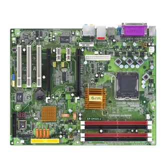
Introduction Section 1 -- Introduction 1-1 Package Contents Contents Optional items A. Mainboard H. SATA II power cable I. Extra USB2.0 port cable B. User’s manual C. Floppy drive cable J. Thermo Stick cable D. HDD drive cable If you need the optional item, please contact your dealer for assistance. -
Page 6: Mainboard Features
Introduction 1-2 Mainboard Features Brief Introduction Socket 775 Socket 775-based motherboards are designed to provide performance enhancements for Intel Pentium 4 processor-based systems, and it also expected to be the next-generation of ® platform innovations. For more details about the Pentium 4 processor, please visit the Intel Web site at http:// ®... -
Page 7: Special Features
Introduction Delivers 8 channel audio to bring you the latest in audio realism from DVD movies and games. Perfect for your home theatre system. Special Features BIOS Features: Ghost BIOS No more worries if BIOS gets corrupted leaving your system unable to boot. The onboard backup BIOS will rescue &... -
Page 8: Mainboard Specification
S-ATA II Four S-ATA II ports with up to 300MB/s bandwidth from ICH7 Onboard EPoX EP1308 LPC bus I/O controller Legacy peripheral interface for PS/2 keyboard & mouse, FDD, Parallel, Serial, and IrDA (v1.0 compliant) Support Hardware Monitoring for fan speed monitoring and CPU temperature sensing... - Page 9 Introduction - Rear panel audio jacks configuration: - c i - c i - c i & r & r BIOS Flash EEPROM with Award Plug&Play BIOS Support EZ Boot for fast bootable device selection Support Magic Health for system hardware status report during system boot-up Support Ghost BIOS for BIOS Recovery Peripheral Interfaces At Rear Panel...
-
Page 10: System Block Diagram
Introduction Support Thermo Stick temperature (Optional) Support Ghost BIOS - Rescue, recover BIOS in an easy step and no more worry of BIOS being corrupted. Powerful utilities for Windows Support Thunder Probe - A hardware diagnostic software to monitor voltage, temperature and speed of a variety of hardware. -
Page 11: Installation
Introduction Section 2 -- Installation Always have the power supply unplugged and powered off when inserting and removing devices within the computer chassis. 2-1 CPU Installation Step 1 Open load plate ( A ) , DO NOT touch socket contacts ( B ). Step 2 Remove protective cover ( C ) from load plate. -
Page 12: Jumper Settings
Introduction 2-2 Jumper Settings JCMOS: Clear CMOS data Jumper If the CMOS data becomes corrupted or you forgot the supervisor or user password, clear the CMOS data to reconfigure the system back to the default values stored in the ROM BIOS. Settings: 1-2: Normal (Default) 2-3: Clear CMOS... -
Page 13: System Memory Configuration
Introduction 2-3 System Memory Configuration The mainboard accommodates four 240-pin DDR2 DIMM sockets. • Supports up to 4GB of 400/533/667MHz DDR2 SDRAM. • Supports unbuffered DIMM configurations defined in JEDEC DDR2 DIMM specification. Dual Channel interface: • Dual channel memory access offers increased system performance. •... -
Page 14: Rear Io Port
Introduction 2-4 Rear IO Port The I/O back panel for this mainboard is shown below. When installing the mainboard into the computer case, use the bundled I/O shield to protect this back panel. RJ45 Parallel Port PS/2 Mouse PS/2 Keyboard S/PDIF-out USB2.0 x 4 ports 7.1 Audio Channel... - Page 15 Introduction Connectors Figure Descriptions CPU / Power / Chassis Fan Power Connectors JCPU_FAN JCPU_FAN: Connect the CPU fan to this JPWR_FAN Control Ground connector. Sense JSYS_FAN +12V JPWR_FAN: Use this connector if you are installing an additional fan in the unit. JSYS_FAN: The chassis fan will provide adequate Ground...
- Page 16 Introduction Connectors Figure Descriptions CUSB3/CUSB4: Four USB2.0 header This mainboard includes 4 additional onboard USB ports. CUSB3 To use these additional USB ports, a USB bracket is CUSB4 required. Please contact your retailer for details. CFP: Case Front Panel Connector HD_LED This LED indicates hard drive activity.
-
Page 17: Bios Setup
Introduction Section 3 -- BIOS Setup 3-1 Main Menu The ROM BIOS contains a built-in Setup program which allows user to modify the basic system configuration and hardware parameters. The modified data is stored in a battery-backed CMOS, so that data will be retained even when the power is turned off. In general, the information saved in the CMOS RAM will stay unchanged unless there is a configuration change in the system, such as hard drive replacement or a device is added. -
Page 18: Standard Cmos Setup
Introduction 3-2 Standard CMOS Setup Choose “STANDARD CMOS FEATURES” in the CMOS SETUP UTILITY Menu. Standard CMOS Features Setup allows the user to configure system settings such as the current date and time, type of hard disk drive installed, floppy drive type, and display type. Memory size is auto-detected by the BIOS and displayed for your reference. -
Page 19: Init Display First
Introduction CPU Feature This field is available only for Pentium CPU Features. ® Hard Disk Boot Priority This item allows you to select the hard disk boot priority. Options: Pri. Master, Pri. Slave, Sec. Master, Sec. Slave, USBHDD0, USBHDD1, USBHDD2, Bootable Add-in cards. -
Page 20: Power Bios Features
Introduction Full Screen LOGO Show This item allows you determine Full Screen LOGO display during POST. Options: Enabled, Disabled. 3-4 POWER BIOS Features This page lets you adjust various parameters to obtain improved performance for overclocking. Warning: Overclocking requires expert knowledge and risks permanent damage to system components. -
Page 21: System Memory Frequency
Introduction (When FSB is 533MHz) (When FSB is 800/1066MHz) Key in the DEC (decimal) number for the CPU CLOCK/SPEED. Overclocking failure will cause no display on the monitor. To overcome this switch off the power supply and switch on again. Restart the system, press and hold < Insert> key. This will revert the BIOS to default or initial setting. -
Page 22: Chipset Voltage
Introduction Voltage Adjust Menu Scroll to Voltage Adjust Menu and press <Enter>. The following screen appears: In the following items, “Default Voltage” indicates the original factory value, and “New Voltage” indicates the value that you assign. CPU Vcore Voltage This item allows you to adjust the CPU Vcore voltage. Options: -0.1000V to +0.2875V in 0.0125V increments and Force 1.625V to 1.850V in 0.025V increments. -
Page 23: Driver & Utiltiy Driver & Utiltiy
Introduction Section 4 -- Driver & Utility Once the operating system has been installed, you need to install the drivers for the mainboard. Please select: Auto Installation Method 1 Manual Installation Method 2 Please visit www.windowsupdate.com to update Windows XP before installing INTEL series driver >>... -
Page 24: Ghost Bios Ghost Bios
Introduction Section 5 -- Ghost BIOS Ghost BIOS helps you to recover from a corrupted BIOS situation, which normally would leave your system unable to boot. Ghost BIOS lets you repair the BIOS yourself saving the hassle of returning the mainboard for repair. - Page 25 Introduction If the screen below is shown, that means your BIOS version is not updated. Refer to Magic Flash steps to update the BIOS.
-
Page 26: Appendix
Introduction Section 6 -- Appendix 6-1 Post Codes 6-1 Post Codes 6-1 Post Codes 6-1 Post Codes 6-1 Post Codes POST (hex) DESCRIPTION Test CMOS R/W functionality. Early chipset initialization: - Disable shadow RAM - Disable L2 cache (socket 7 or below) - Program basic chipset registers Detect memory - Auto-detection of DRAM size, type and ECC. - Page 27 Introduction Initial interrupts vector table. If no special specified, all H/Winterrupts are directed to SPURIOUS_INT_HDLR & S/W interrupts to URIOUS_soft_HDLR. Reserved Initial EARLY_PM_INIT switch. Reserved Load keyboard matrix (notebook platform) Reserved HPM initialization (notebook platform) Reserved Check validity of RTC value: e.g.
- Page 28 Introduction 4A-4Dh Reserved Program MTRR of M1 CPU Initialize L2 cache for P6 class CPU & program CPU with proper cacheable range. Initialize the APIC for P6 class CPU. On MP platform, adjust the cacheable range to smaller one in case the cacheable ranges between each CPU are not identical.
- Page 29 Introduction Detect serial ports & parallel ports. 78h-79h Reserved Detect & install co-processor 7B-7Eh Reserved Switch back to text mode if full screen logo is supported. -If errors occur, report errors & wait for keys -If no errors occur or F1 key is pressed to continue: Clear EPA or customization logo.
- Page 30 Introduction...
Need help?
Do you have a question about the EP-5P945-J3 and is the answer not in the manual?
Questions and answers