
Related Manuals for EPOX EP-6VBA


Summary of Contents for EPOX EP-6VBA
- Page 1 TRADEMARK All products and company names are trademarks or registered trademarks of their respective holders. These specifications are subject to change without notice. Manual Revision 4.2 May 25, 1999...
- Page 2 If your retailer can not help, you may E- Mail us with any questions at the following address tech@epox.com Record your serial number before installing your EP-6VBA mainboard. (the serial number is located near the ISA slots at the edge of the board)
- Page 3 Always work on an antistatic surface to avoid possible damage to the motherboard from static discharge. We assume no responsibility for any damage to the EP-6VBA mainboard that results from failure to follow installation instructions or failure to observe safety precautions.
-
Page 4: Table Of Contents
System Block Diagram ... 1-7 Section 2 Features EP-6VBA Features ... 2-1 Section 3 Installation EP-6VBA Detailed Layout ... 3-1 Easy Installation Procedure Configure DIP Switch... 3-3 System Memory Configuration ... 3-4 Installing a Pentium Device Connectors ... 3-9 External Modem Ring-in Power On and Keyboard Power On Function (KBPO) ... - Page 5 EP-6VBA Power Management Setup ... 4-11 PNP/PCI Configuration ... 4-15 Load Setup Defaults ... 4-17 Integrated Peripherals... 4-17 Sensor and CPU Speed Setup ... 4-22 Change Supervisor or User Password ... 4-24 IDE HDD Auto Detection ... 4-25 HDD Low Level Format... 4-27 Save &...
- Page 6 EP-6VBA...
-
Page 7: Introduction
EP-6VBA ü ü ü ü ü EP-6VBA mainboard ü ü ü ü ü EP-6VBA user’s manual ü ü ü ü ü Floppy ribbon cable ü ü ü ü ü Hard drive ribbon cables ü ü ü ü ü Foldable Retention Module... - Page 8 III Processor, like the Pentium ® II Processor to deliver higher performance ® ® II or Pentium ® II or Pentium ® III Processor utilizes Single Edge Contact (S.E.C.) EP-6VBA ® ® III Processor, from a system ® III Processor...
- Page 9 EP-6VBA The entire enclosed product is called the Pentium The packaging technology and each of the physical elements of the product are referred to using accurate technical descriptions. This allows clear reference to the products as just a processor. This is the model used in past packaging tech- nologies like PGA, TCP, PQFP, DIP, etc.
- Page 10 Typically, 3D graphics rendering requires a tremendous amount of memory, and demands ever increasing throughput speed as well. As 3D products for the personal computer become more and more popular, these demands will only increase. This will cause a rise in costs for both end users and manufacturers.
- Page 11 EP-6VBA The EP-6VBA is designed with ATX form factor - the new industry standard of chassis. ATX form factor is essentially a Baby-AT baseboard rotated 90 degrees within the chassis enclosure and a new mounting configuration for the power supply. With these changes the processor is relocated away from the expansion slots, allowing them all to hold full length add-in cards.
- Page 12 Introduction The EP-6VBA is equipped with an I/O back panel. Please use the appropriate I/ O shield (figure 3). PS/2 Mouse USB port PS/2 KEYBOARD Figure 3: I/O back panel layout The EP-6VBA has a single 20-pin connector for ATX power supplies. For ATX power supplies that support the Remote On/Off feature, this should be connected to the systems front panel for system Power On/Off button.
-
Page 13: Pentium ® Iii Processor
EP-6VBA Introduction Pentium II Pentium III Processor Figure 5: System Block Diagram Page 1-7... - Page 14 EP-6VBA Introduction Page 1-8...
-
Page 15: Ep-6Vba Features
(2) independent high performance PCI IDE interfaces capable of supporting PIO Mode 3/4 and Ultra DMA 33/66 devices. The EP-6VBA supports (5) PCI Bus Master slots and a jumperless PCI INT# control scheme which reduces configuration confusion when plugging in PCI card(s). - Page 16 • Supports CPU Hardware sleep and SMM (System Management Mode). • Supports Keyboard power ON function (KBPO). • Built-in WOL (Wake-up On Lan) Connector. • Built-in AC97 PCI Audio. Page 2-2 EP-6VBA ® 95/98.
-
Page 17: Installation
EP-6VBA Installation Page 3-1... -
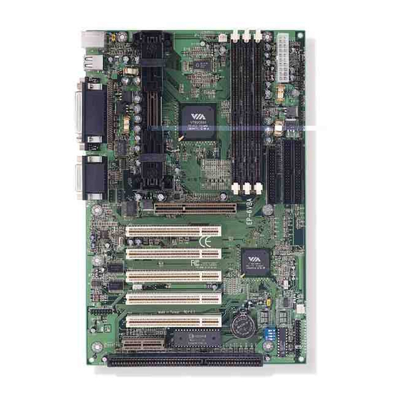
Page 18: Ep-6Vba Detailed Layout
EP-6VBA Installation EP-6VBA Detailed Layout Figure 1 Page 3-2... -
Page 19: External Modem Ring-In Power On And Keyboard Power On Function (Kbpo)
EP-6VBA The following must be completed before powering on your new system: 3-1. Configure DIP Switch and Jumper to match your hardware 3-2. System memory Configuration 3-3. Install Pentium II or Pentium III Processor 3-4. Device Connectors External Modem Ring-in Power ON and Keyboard Power ON Functions (KBPO) We design this motherboard with a DIP Switch to make your install fast and easy. - Page 20 Installation The EP-6VBA supports (3) 168-pin DIMMs (Dual In-line Memory Module). The DIMMs can be either EDO (Enhanced Data Out) or SDRAM (Synchronized DRAM). • DIMM SDRAM may be 83MHz (12ns), 100MHz (10ns) or 125MHz (8ns) bus speed. • If you use both 50ns and 60ns memory you must configure your BIOS to read 60ns.
- Page 21 EP-6VBA Figure 3 displays the notch marks and what they should look like on your DIMM memory module. DIMMs have 168-pins and two notches that will match with the onboard DIMM socket. DIMM modules are installed by placing the chip firmly into the socket at a 90 degree angle and pressing straight down (figure 4) until it fits tightly into the DIMM socket (figure 5).
- Page 22 EP-6VBA Installation Figure 5 DIMM Module clip after installation To remove the DIMM module simply press down both of the white clips on either side and the module will be released from the socket. Page 3-6...
- Page 23 EP-6VBA The EP-6VBA uses the Single Edge Contact (SEC) slot for a Pentium processor packaged in an SEC cartridge. The SEC slot is not compatible with other non-Pentium II processors. Please have ready the following list of components so that we may install the processor onto the motherboard.
- Page 24 Large Hole for Heat Sink Base Bottom fin of heatsink Page 3-8 Figure 7 CPU Car tr idge SLOT 1 Small Hole for Heat Sink Base Figure 8 Top half of the support Figure 9 EP-6VBA Motherboard Layout Bottom fin of heatsink...
- Page 25 EP-6VBA Please install the motherboard into the chassis. Now that your motherboard is installed you are ready to connect all your connections (figure 10). PS/2 Mouse USB port PS/2 KEYBOARD Chassis Panel Connector • Power LED, Speaker, Reset Turbo LED, HDD LED, IR Conn., Sleep/Power_ON CPU Fan Power •...
- Page 26 1. Power LED(+) 2. N/C 3. GND Speaker - Connect to the system's speaker for beeping 1. Speaker 2. N/C Reset - Closed to restart system. Page 3-10 EP-6VBA 4. GND 5. IRTX 4. NC 5. GND 3. GND 4. GND...
-
Page 27: Keyboard Power On Function (Kbpo)
On the basis of bounded functions in I/O chipset, the two serial ports are able to support the External Modem Ring-in Power ON function. Once users connect the external modem to COM1 or COM2, the EP-6VBA mainboard allows users to turn on their system through the remote and host's dial-up control. - Page 28 EP-6VBA Installation Page 3-12...
-
Page 29: Standard Cmos Setup
EP-6VBA Award’s ROM BIOS provides a built-in Setup program which allows user to modify the basic system configuration and hardware parameters. The modified data will be stored in a battery-backed CMOS, so that data will be retained even when the power is turned off. In general, the information saved in the CMOS RAM will stay unchanged unless there is a configuration change in the system, such as hard drive replacement or a device is added. - Page 30 ROM PCI/ISA BIOS(2A6LGPAA) STANDARD CMOS SETUP AWARD SOFTWARE, INC. CYLS HEAD PRECOMP LANDZONE Base Memory Extended Memory Other Memory Total Memory : Select Item : Change Color EP-6VBA SECTORS MODE Auto Auto Auto Auto 640K 392192K 384K 393216K PU/PD/+/- : Modify...
-
Page 31: Virus Warning
EP-6VBA Note: The “Halt On:” field is used to determine when to halt the system by the BIOS if an error occurs. Note: Floppy 3 Mode support is a mode used to support a special 3.5” drive used in Japan. This is a 3.5” disk that stores only 1.2 MB, the default setting for this is disabled. - Page 32 Disabled: Disabled the CPU’s L2 cache to support ECC function. Quick Power On Self Test: This category speeds up the Power On Self Test (POST). The default is Enabled. Enabled: This setting will shorten or skip of the items checked during POST. Disabled: Normal POST. Page 4-4 EP-6VBA...
- Page 33 EP-6VBA Boot Sequence: This category determines which drive is searched first by the O/S (Operating System). The default is A,C,SCSI. The following is your list of options: [A, C, SCSI] - [C, A, SCSI] - [C, CD-ROM, A] - [CD-ROM, C, A]...
- Page 34 15: 15 characters per second. 20: 20 characters per second. 24: 24 characters per second. 30: 30 characters per second. Typematic Delay (msec): This setting controls the time between the first and the second character displayed by typematic auto-repeat. Page 4-6 8: 8 characters per second. EP-6VBA...
- Page 35 EP-6VBA The default is 250. 250: 250 msec. 500: 500 msec. 750: 750 msec. 1000: 1000 msec. Security Option: This category allows you to limit access to the System and Setup, or just to Setup. The default is Setup. System: The system will not boot and the access to Setup will be denied if the correct password is not entered at the prompt.
- Page 36 OnChip USB USB Keyboard Support OnChip Sound OnChip Modem Esc : Quit F1 : Help F5 : Old Values F7 : Load Setup Defaults EP-6VBA : Enabled : Disabled : Enabled : Disabled : Select Item PU/PD/+/- : Modify (Shift) F2...
- Page 37 EP-6VBA Bank 0/1, 2/3, 4/5 DRAM Timing: This value in this field is set by the system board manufacturer, depending on whether the board has paged DRAMs or EDO (extended data output) DRAMs. The Choice: Bank 0/1, 2/3, 4/5. SDRAM Cycle length: This setting defines the CAS timing parameter of the SDRAM in terms of clocks.
- Page 38 32: 32MB of systems memory accessable by the AGP card. 64: 64MB of systems memory accessable by the AGP card. 128: 128MB of systems memory accessable by the AGP card. 256: 256MB of systems memory accessable by the AGP card. Page 4-10 EP-6VBA...
-
Page 39: Onchip Usb
EP-6VBA OnChip USB: Select Enabled if your system contains a Universal Serial Bus(USB) controller and you have a USB peripheral. USB Keyboard Support: This controls the activation status of an optional USB keyboard that may be attached. The default is disabled. - Page 40 Select this option if your monitor supports the Display Power Management Signaling (DPMS) standard of the Video Electronics Standards Association (VESA). Use the software supplied for your video subsystem to select video power management values. Blank Screen: System only writes blanks to the video buffer. Page 4-12 EP-6VBA...
-
Page 41: Modem Use Irq
N/A: No IRQ is used. 4: IRQ 4 7: IRQ 7 10: IRQ 10 The EP-6VBA supports HDD Power Down, Doze and Standby power saving functions when using the Intel Pentium II Processor. The default is Disabled Soft-Off by PWR-BTTN: Use this to select your soft-off function. - Page 42 When set to Enabled, any event occurring to the Modem Ring will awaken a system which has been powered down. Primary INTR: When set to On (default), any event occurring at will awaken a system which has been powered down. Page 4-14 EP-6VBA...
- Page 43 EP-6VBA The PNP/PCI configuration program is for the user to modify the PCI/ISA IRQ signals when various PCI/ISA cards are inserted in the PCI or ISA slots. WARNING: Conflicting IRQ’s may cause the system to not find certain devices. PNP OS Installed...
- Page 44 Select Enabled to support compliance with PCI specifica- tion version 2.1. The Choice: Enabled, Disabled. PCI #2 Access #1 Retry: This item allows you enabled/disable the PCI #2 Access #1 Retry. The Choice: Enabled, Disabled. Page 4-16 EP-6VBA...
-
Page 45: Ide Prefetch Mode
EP-6VBA The “LOAD SETUP DEFAULTS” function loads the system default data directly from ROM and initializes the associated hardware properly. This function will be necessary only when the system CMOS data is corrupted. OnChip IDE Channel0 : Enabled OnChip IDE Channel1... - Page 46 Primary Master UDMA: This allows you to select the mode of operation for the hard drive. The default is Auto. Auto: The computer will select the optimal setting. Disabled: The hard drive will run in normal mode. Page 4-18 EP-6VBA...
- Page 47 EP-6VBA Primary Slave UDMA: This allows you to select the mode of operation for the hard drive. The default is Auto. Auto: The computer will select the optimal setting. Disabled: The hard drive will run in normal mode. Secondary Master UDMA: This allows you to select the mode of operation for the hard drive.
- Page 48 378H: Enable Onboard LPT port and address is 378H and IRQ7. 278H: Enable Onboard LPT port and address is 278H and IRQ5. 3BCH: Enable Onboard LPT port and address is 3BCH and IRQ7. Disabled: Disable Onboard LPT port. Page 4-20 EP-6VBA...
- Page 49 EP-6VBA Onboard Parallel Mode: This field allows the user to select the parallel port mode. The default is ECP+EPP. Normal: Standard mode. IBM PC/AT Compatible bidirectional parallel port. EPP: Enhanced Parallel Port mode. ECP: Extended Capabilities Port mode. EPP+ECP: ECP Mode & EPP Mode.
-
Page 50: Auto Detect Dimm/Pci Clk
Vcore : 1.87V 3.3V : 3.28V : 11.88V Esc : Quit F1 : Help F5 : Old Values F7 : Load Setup Defaults EP-6VBA : 31 C/87 : 24 C/75 : 0 RPM : 0 RPM : 1.52V : 5.02V... - Page 51 EP-6VBA CPU Host Clock (CPU/PCI): Allows the external clock to be modified depending upon what FSB has been selected. Should not be used to clock processor faster than it was designed for. (See page A-11). The default is Default. 66MHz FSB options: Default, 66.8, 68.5, 75, and 83MHz.
- Page 52 3. After pressing the [Enter] key (ROM password if the option was not used) or current password (user-defined password), the user can change the password and store new one in CMOS RAM. A maximum of 8 characters can be entered. Page 4-24 EP-6VBA...
- Page 53 EP-6VBA The “IDE HDD auto detection” utility is a very useful tool, especially when you do not know which kind of hard disk type you are using. You can use this utility to detect the correct disk type installed in the system automatically. But now you can set HARD DISK TYPE to Auto in the STANDARD CMOS SETUP.
- Page 54 Maximum HDD size: no. Cylinder x no. Head x no. Sector x bytes per sector Page 4-26 (1024) ( 255) ( 63) ( 512) 8.4 GigaBytes SECTOR MODE NORMAL LARGE (1024) ( 32) ( 63) ( 512) 1 GigaByte EP-6VBA...
- Page 55 EP-6VBA Note: To support LBA or LARGE mode of HDDs, there must be some software involved. All the software is located in the Award HDD Service Routine (INT 13h). It may fail to access a HDD with LBA (LARGE) mode selected if you are running under an Operating System which replaces the whole INT 13h.
- Page 56 EP-6VBA BIOS Page 4-28...
- Page 57 EP-6VBA Address Range Size [00000-7FFFF] 512K [80000-9FBFF] 127K [9FC00-9FFFF] installed [A0000-C7FFF] 160K [C8000-DFFFF] ROMs [E0000-EEFFF] [EF000-EFFFF] [F0000-F7FFF] [F8000-FCFFF] [FD000-FDFFF] [FE000-FFFFF] [000-01F] DMA controller.(Master) [020-021] INTERRUPT CONTROLLER.(Master) [022-023] CHIPSET control registers. I/O ports. [040-05F] TIMER control registers. [060-06F] KEYBOARD interface controller.(8042) [070-07F] RTC ports &...
- Page 58 Parity check error. IRQ (H/W): System TIMER interrupt from TIMER 0. KEYBOARD output buffer full. Cascade for IRQ 8-15. SERIAL port 2. SERIAL port 1. PARALLEL port 2. FLOPPY DISK (SMC CHIP). PARALLEL port 1. RTC clock. Available. Available. Available. EP-6VBA...
- Page 59 EP-6VBA PS/2 Mouse. MATH coprocessor. Onboard HARD DISK (IDE1) channel. Onboard HARD DISK (IDE1) channel. RTC & CMOS: Seconds. Second alarm. Minutes. Minutes alarm. Hours. Hours alarm. Day of week. Day of month. Month. Year. Status register A. Status register B.
- Page 60 EP-6VBA Appendix...
- Page 61 EP-6VBA ISA POST codes are typically output to I/O port address 80h. POST (hex) DESCRIPTION 01-02 Reserved. Turn off OEM specific cache, shadow. 1. Initialize EISA registers (EISA BIOS only). 2. Initialize all the standard devices with default values Standard devices includes.
- Page 62 2. Program all onboard super I/O chips (if any) including COM ports, LPT ports, FDD port ... according to setup value. 33-3B Reserved. Set flag to allow users to enter CMOS Setup Utility. 1. Initialize Keyboard. 2. Install PS2 mouse. EP-6VBA...
- Page 63 EP-6VBA Try to turn on Level 2 cache. Note: Some chipset may need to turn on the L2 cache in this stage. But usually, the cache is turn on later in POST 61h. 3F-40 Reserved. 1. Program the rest of the Chipset's value according to Setup.
- Page 64 2. Clear memory that have been used. 3. Boot system via INT 19H. System Booting. This means that the BIOS already pass the control right to the operating system. POST (hex) DESCRIPTION If interrupt occurs in protected mode. Unclaimed NMI occurs.0 EP-6VBA...
-
Page 65: Load Setup Defaults
EP-6VBA NOTE: The "LOAD SETUP DEFAULTS" function loads the system default data directly from ROM and initializes the associated hardware properly. This function will be necessary when you accept this mainboard, or the system CMOS data is corrupted. ROM PCI/ISA BIOS(2A6LGPAA) - Page 66 EP-6VBA Appendix A-10...
- Page 67 EP-6VBA Install windows 95/98 Sound Driver **Installation Notes: You must already have Windows 95/98 install on your computer. 1. Login windows 95/98, then click “My Computer” icon, “Control Panel” icon, and “System” icon. 2. Before the Driver install into windows 95/98, you will find a yellow question mark still exits the “Other Devices”...
- Page 68 9. Re-key in the driver location to the "Copy files from:"(refer step 4) click "ok", the you will be complete to install driver. Remember to restart your computer to take it into effect, show in figure 1-2 below. A-12 Figure 2 EP-6VBA...
- Page 69 EP-6VBA Install windows 95/98/NT V4.0 Driver **Installation Notes: 1. Before installing Windows 95 Driver, please do install Windows 95 OSR2.0 "USB SUPP.EXE" first (upgrades OS up to OSR2.1 level). 2. The Operation System(OS) and DirectX 5.0 or 6.0 must be installed into the system prior to installation.
Need help?
Do you have a question about the EP-6VBA and is the answer not in the manual?
Questions and answers