Table of Contents
Advertisement
Quick Links
EP-68LXR
EP-68LXR
EP-68LXR
EP-68LXR
EP-68LXR
A Pentium
A Pentium
II Processor based AGP mainboard
II Processor based AGP mainboard
A Pentium
A Pentium
A Pentium
II Processor based AGP mainboard
II Processor based AGP mainboard
II Processor based AGP mainboard
® ® ® ® ®
TRADEMARK
All products and company names are trademarks or
registered trademarks of their respective holders.
These specifications are subject to change without
notice.
Manual Revision 2.3
June 25, 1998
Advertisement
Table of Contents

Related Manuals for EPOX EP-68LXR


Summary of Contents for EPOX EP-68LXR
- Page 1 EP-68LXR EP-68LXR EP-68LXR EP-68LXR EP-68LXR A Pentium A Pentium II Processor based AGP mainboard II Processor based AGP mainboard A Pentium A Pentium A Pentium II Processor based AGP mainboard II Processor based AGP mainboard II Processor based AGP mainboard ®...
- Page 2 If your retailer can not help, you may E-Mail us with any questions at the following address tech@epox.com Record your serial number before installing your EP-68LXR mainboard. (the serial number is located near the ISA slots at the edge of the board)
- Page 3 In no event shall EPoX be liable for any loss or profits, loss of business, loss of use or data, interruption of business or for...
-
Page 4: Table Of Contents
System Block Diagram ........1-6 Section 2 Features EP-68LXR Features ........2-1 Section 3 Installation EP-68LXR Detailed Layout ......3-1 Easy Installation Procedure Configure DIP Switch ........3-2 System Memory Configuration ......3-3 ® Installing a Pentium II Processor ....3-6 Device Connectors ......... - Page 5 EP-68LXR Integrated Peripherals ........4-19 Change Supervisor or User Password ..... 4-24 IDE HDD Auto Detection ....... 4-24 HDD Low Level Format ......... 4-27 Save & Exit Setup .......... 4-27 Exit Without Saving ......... 4-27 Section 5 DMI Access ........... 5-1...
-
Page 6: Introduction
Section 1 INTRODUCTION Components Checklist ü ü ü ü ü EP-68LXR mainboard ü ü ü ü ü EP-68LXR user’s manual ü ü ü ü ü Floppy ribbon cable ü ü ü ü ü Hard drive ribbon cable Heatsink Support Unit (optional) PS/2 Mouse Connector ü... -
Page 7: Overview
Introduction EP-68LXR Overview Pentium II ® ® The Pentium II Processor is the follow-on to the Pentium Processor. The ® ® Pentium II Processor, like the Pentium Pro processor, implements a Dynamic Execution micro-architecture -- a unique combination of multiple branch prediction, ®... -
Page 8: Cartridge Terminology
EP-68LXR Introduction processor. This is the model used in past packaging technologies like PGA, TCP, PQFP, DIP, etc. S.E.C. Cartridge Terminology ® • Pentium II Processor The new enclosed card packaging technology is called a “Single Edge Contact cartridge.” This is similar to previous names for packaging technology such as PGA or TCP. -
Page 9: Accelerated Graphics Port
Introduction EP-68LXR Accelerated Graphics Port (AGP or A.G.P.) Typically, 3D graphics rendering requires a tremendous amount of memory, and demands ever increasing throughput speed as well. As 3D products for the personal computer become more and more popular, these demands will only increase. This will cause a rise in costs for both end users and manufacturers. -
Page 10: Power-On/Off (Remote)
Off button should be a momentary button that is normally open. The EP-68LXR has been designed with “Soft Off" functions. You can turn Off the system from one of two sources: The first is the front panel Power On/Off button, and the other is the "Soft Off"... -
Page 11: System Block Diagram
Introduction EP-68LXR System Block Diagram PCI Bridge and memory controller 443LX/443EX PIIX4/PIIX4E I/O Bridge Figure 5: System Block Diagram Page 1-6... -
Page 12: Features
Supports (2) 16 bit ISA slots, (3) 32 bit PCI slots, (1) AGP slot and provides (2) independent high performance PCI IDE interfaces capable of supporting PIO Mode 3/4 and Ultra DMA 33 devices. The EP-68LXR supports (3) PCI Bus Master slots and a jumperless PCI INT# control scheme which reduces configuration confusion when plugging in PCI card(s). - Page 13 Features EP-68LXR • Supports the Universal Serial Bus (USB) Header. The onboard PIIX4/PIIX4E chip provides the means for connecting PC peripherals such as; keyboards, joysticks, telephones, and modems. • Built-in ATX 20-pin and AT 12-Pin power supply connector. • ®...
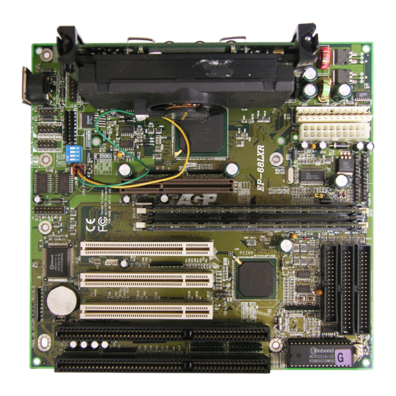
- Page 14 CPU Cartridge SLOT 1 Intel 443LX/443EX PCIset IR CONN. HD/LED AGP SLOT TB/LED POWER_ON DIMM 1 Bank 0 DIMM 2 Bank 1 PCI Slot #3 PCI Slot #2 PCI Slot #1 ISA Slot #1 IDE1 IDE2 ISA Slot #2...
-
Page 15: Easy Installation Procedure
Section 3-1 Configure DIP Switch EPoX designs all motherboards with a DIP Switch to make your install fast and easy. The following will describe all of the DIP Switch that you are required to set before moving on to step 3-2. -
Page 16: System Memory Configuration
Installation Section 3-2 System Memory Configuration Memory Layout The EP-68LXR supports (2) 168-pin DIMMs (Dual In-line Memory Module). The DIMMs can be either EDO (Enhanced Data Out) or SDRAM (Synchronized DRAM). • DIMM SDRAM may be 83MHz (12ns), 100MHz (10ns) or 120MHz (8ns) bus speed. - Page 17 Installation EP-68LXR * SDRAM only supports 8, 16, 32, 64, 128MB DIMM modules. Table 1 DIMM Module Installation Figure 5 displays the notch marks and what they should look like on your DIMM memory module. DIMMs have 168-pins and two notches that will match with the onboard DIMM socket.
- Page 18 EP-68LXR Installation Figure 5 DIMM Module clip before installation Figure 6 DIMM Module clip after installation To remove the DIMM module simply press down both of the white clips on either side and the module will be released from the socket.
-
Page 19: Installing A Pentium Ii Processor
EP-68LXR Section 3-3 Installing a Pentium II Processor The EP-68LXR uses the Single Edge Contact (SEC) slot for a Pentium II processor packaged in an SEC cartridge. The SEC slot is not compatible with other non- Pentium II processors. Please have ready the following list of components so that we may install the proces- sor onto the motherboard. - Page 20 EP-68LXR Installation bottom make sure you press firmly on SEC cartridge to firmly secure into the Slot 1 Socket. Now we need to secure the heatsink with the top half of the support (figure 11). Take the top piece of the support and slide it into the bottom fin (figure 11) on the heatsink and then push forward until it clips into the bottom base (figure 9) that is already there (figure 11).
-
Page 21: Device Connectors
Installation EP-68LXR Section 3-4 Device Connectors Please install the motherboard into the chassis. Now that your motherboard is installed you are ready to connect all your connections (figure 12). K B C o n n. Figure 12 Chassis Panel Connector •... - Page 22 4 seconds before the system turns off). When the system is in 4 sec delay mode, EPoX has added a special feature to make the system go into suspend mode when the button is pressed momentarily.
-
Page 23: Award Bios Setup
EP-68LXR BIOS Section 4 AWARD BIOS SETUP BIOS Instructions Award’s ROM BIOS provides a built-in Setup program which allows user to modify the basic system configuration and hardware parameters. The modified data will be stored in a battery-backed CMOS, so that data will be retained even when the power is turned off. -
Page 24: Standard Cmos Setup
BIOS EP-68LXR The menu displays all the major selection items. Select the item you need to reconfigure. The selection is made by moving the cursor (press any direction key ) to the item and pressing the ‘Enter’ key. An on-line help message is displayed at the bottom of the screen as the cursor is moved to various items which provides a better understanding of each function. -
Page 25: Bios Features Setup
Selecting the “BIOS FEATURES SETUP” option in the CMOS SETUP UTILITY menu allows users to change system related parameters in the displayed menu. This menu shows all of the manufacturer’s default values for the EP-68LXR. Pressing the [F1] key will display a help message for the selected item. - Page 26 BIOS EP-68LXR Enabled: Activates automatically when the system boots up causing a warning message to appear when anything attempts to access the boot sector. Disabled: No warning message will appear when anything attempts to access the boot sector. Note: Many disk diagnostic programs that access the boot sector table can trigger the virus warning message.
- Page 27 EP-68LXR BIOS Swap Floppy Drive: This will swap your physical drive letters A & B if you are using two floppy disks. The default is Disabled. Enabled: Floppy A & B will be swapped under the O/S. Disabled: Floppy A & B will be not swapped.
- Page 28 BIOS EP-68LXR Typematic Rate Setting: This determines the keystrokes repeat rate. The default is Disabled. Enabled: Allows typematic rate and typematic delay programming. Disabled: The typematic rate and typematic delay will be controlled by the keyboard controller in your system.
- Page 29 EP-68LXR BIOS OS Select For DRAM > 64MB: Some operating systems require special handling. Use this option only if your system has greater than 64MB of memory. The default is Non-OS2. OS2: Select this if you are running the OS/2 operating system with greater than 64MB of RAM.
-
Page 30: Chipset Features Setup
BIOS EP-68LXR 4-3 Chipset Features Setup Choose the “CHIPSET FEATURES SETUP” in the CMOS SETUP UTILITY menu to display following menu. Figure 4: Chipset Features Setup Auto Configuration: This selects predetermined optimal values of the chipset parameters. The default is Enabled. - Page 31 EP-68LXR BIOS 50ns: (Faster) Burst Wait State, for 50ns EDO DRAM. 60ns: (Slower) Burst Wait State, for 60ns Fast Page Mode/EDO DRAM. MA Additional Wait State: This allows the option to insert an additional wait state before the beginning of a memory read. Use of this option may be required to achieve compatibility with some system configurations.
- Page 32 BIOS EP-68LXR x222: Use of this option may cause conflicts with some system configurations. x333: This is used for standard system configurations. DRAM Data Integrity Mode: Use this option to configure the type of DRAM in your system. The default is Non-ECC.
- Page 33 EP-68LXR BIOS 8 Bit I/O Recovery Time: This function allows you to set the wait state that is added to an 8 bit ISA instruction originated by the PCI bus. The default is 3. NA: No wait state 8: 8 wait states...
- Page 34 BIOS EP-68LXR AGP Aperture Size: The amount of system memory that the AGP card is allowed to share. The default is 4. 4: 4MB of systems memory accessable by the AGP card. 8: 8MB of systems memory accessable by the AGP card.
-
Page 35: Power Management Setup
EP-68LXR BIOS Current CPU Temperature: This is the current temperature of the CPU. Current Power FAN Speed: The current power fan speed in RPMs. Current CPU FAN Speed: The current CPU fan speed in RPMs. Current Chassis FAN Speed: The current chassis fan speed in RPMs. - Page 36 BIOS EP-68LXR Power Management: Use this to select your Power Management selection. The default is User define. Disabled: The system operates in NORMAL conditions (Non-GREEN), and the Power Management function is disabled. Max. saving: Maximum power savings. Inactivity period is 1 minute in each mode.
- Page 37 9: IRQ 9 10: IRQ 10 11: IRQ 11 The EP-68LXR supports HDD Power Down, Doze and Standby power saving functions when using the Intel Pentium II Processor. The default is Disabled Doze Mode: The “Doze” mode timer starts to count when no “PM events” have occurred.
- Page 38 BIOS EP-68LXR Resume by Ring: This option is used to set the remote ring in feature. This option is only available when Power Loss Recovery is Enabled. The default is Enabled. Enabled: The system can use remote ring-in to wake the system up.
-
Page 39: Pnp/Pci Configuration
EP-68LXR BIOS 4-5 PNP/PCI Configuration The PNP/PCI configuration program is for the user to modify the PCI/ISA IRQ signals when various PCI/ISA cards are inserted in the PCI or ISA slots. WARNING: Conflicting IRQ’s may cause the system to not find certain devices. - Page 40 BIOS EP-68LXR Reset Configuration Data: This setting allows you to clear ESCD data. The default is Disabled Disabled: Normal Setting. Enabled: If you have plugged in some Legacy cards to the system and they were recorded into ESCD (Extended System Configuration Data), you can set this field to Enabled in order to clear ESCD.
-
Page 41: Load Setup Defaults
EP-68LXR BIOS 4-6 Load Setup Defaults The “LOAD SETUP DEFAULTS” function loads the system default data directly from ROM and initializes the associated hardware properly. This function will be necessary only when the system CMOS data is corrupted. 4-7 Integrated Peripherals... - Page 42 BIOS EP-68LXR IDE HDD Block Mode: IDE Block Mode allows the controller to access blocks of sectors rather than a single sector at a time. The default is Enabled. Enabled: Enabled IDE HDD Block Mode. Provides higher HDD transfer rates.
- Page 43 EP-68LXR BIOS Mode 0~4: Manually set the IDE Programmed interrupt mode. IDE Primary Master UDMA: This allows you to select the mode of operation for the hard drive. The default is Auto. Auto: The computer will select the optimal setting.
- Page 44 BIOS EP-68LXR OnBoard Primary PCI IDE: This option turns on and off the onboard primary IDE. The default is enabled. Enabled: This activates the primary PCI IDE. Disabled: This disables the primary PCI IDE and frees up the resource. OnBoard Secondary PCI IDE: This option turns on/off the onboard secondary IDE.
- Page 45 EP-68LXR BIOS Onboard IR Controller: IrDA Controller. The default is Enabled. IR Address Select: The port location of the IR controller. The default is 2E8H. IR Mode: The mode of the IR controller. The default is IrDA IR Transaction Delay: The default is Enabled.
-
Page 46: Change Supervisor Or User Password
BIOS EP-68LXR 4-8 Change Supervisor or User Password To change the password, choose the “SUPERVISOR PASSWORD or USER PASSWORD” option from the CMOS SETUP UTILITY menu and press [Enter]. NOTE: Either “Setup” or “System” must be selected in the “Security Option”... - Page 47 EP-68LXR BIOS Figure 8: IDE HDD Auto Detection NOTE: HDD Modes The Award BIOS supports 3 HDD modes : NORMAL, LBA & LARGE NORMAL mode Generic access mode in which neither the BIOS nor the IDE controller will make any transformations during accessing.
- Page 48 BIOS EP-68LXR LBA (Logical Block Addressing) mode: A new HDD accessing method to overcome the 528 Megabyte bottleneck. The number of cylinders, heads & sectors shown in setup may not be the number physically contained in the HDD. During HDD accessing, the IDE controller will transform the logical address described by sector, head &...
-
Page 49: Hdd Low Level Format
EP-68LXR BIOS UNIX operating systems do not support either LBA or LARGE and must utilize the Standard mode. UNIX can support drives larger than 528MB. 4-10 HDD Low Level Format Interleave: Select the interleave number of the hard disk drive you wish to perform a low level format on. -
Page 50: Dmi Access
EP-68LXR DMI Access Section 5 DMI ACCESS DMI Access DMI, or desktop Management Interface, is a feature that is able to auto-detect and record information about your computer system. This information is used by comput- ing professionals to accurately determine your system configuration and to diagnose and resolve problems. -
Page 51: Appendix
EP-68LXR Appendix Appendix A: A-1 MEMORY MAP Address Range Size Description [00000-7FFFF] 512K Conventional memory [80000-9FBFF] 127K Extended Conventional memory [9FC00-9FFFF] Extended BIOS data area if PS/2 mouse is installed [A0000-C7FFF] 160K Available for Hi DOS memory [C8000-DFFFF] Available for Hi DOS memory and adapter ROMs... -
Page 52: Timer & Dma Channels Map
Appendix EP-68LXR [3D0-3DF] CGA adapter. [3F0-3F7] FLOPPY DISK controller. [3F8-3FF] SERIAL port 1. A-3 TIMER & DMA CHANNELS MAP TIMER MAP: TIMER Channel 0 System timer interrupt. TIMER Channel 1 DRAM REFRESH request. TIMER Channel 2 SPEAKER tone generator. DMA CHANNELS: DMA Channel 0 Available. -
Page 53: Rtc & Cmos Ram Map
EP-68LXR Appendix Onboard HARD DISK (IDE1) channel. Onboard HARD DISK (IDE1) channel. A-5 RTC & CMOS RAM MAP RTC & CMOS: Seconds. Second alarm. Minutes. Minutes alarm. Hours. Hours alarm. Day of week. Day of month. Month. Year. Status register A. -
Page 54: Post Codes
Appendix EP-68LXR Appendix B: B-1 POST CODES ISA POST codes are typically output to I/O port address 80h. POST (hex) DESCRIPTION 01-02 Reserved. Turn off OEM specific cache, shadow. 1. Initialize EISA registers (EISA BIOS only). 2. Initialize all the standard devices with default values Standard devices includes. - Page 55 EP-68LXR Appendix Initialization of the BIOS Data Area. (40:ON - 40:FF) 1. Program some of the Chipset's value according to Setup. (Early Setup Value Program) 2. Measure CPU speed for display & decide the system clock speed. 3. Video initialization including Monochrome, CGA, EGA/VGA. If no display device found, the speaker will beep.
- Page 56 Appendix EP-68LXR Try to turn on Level 2 cache. Note: Some chipset may need to turn on the L2 cache in this stage. But usually, the cache is turn on later in POST 61h. 3F-40 Reserved. 1. Program the rest of the Chipset's value according to Setup.
-
Page 57: Unexpected Errors
EP-68LXR Appendix 1. Try to turn on Level 2 cache. Note: If L2 cache is already turned on in POST 3D, this part will be skipped. 2. Set the boot up speed according to Setup setting. 3. Last chance for Chipset initialization. -
Page 58: Load Setup Defaults
Appendix EP-68LXR Appendix C NOTE: The "LOAD SETUP DEFAULTS" function loads the system default data directly from ROM and initializes the associated hardware properly. This function will be necessary when you accept this mainboard, or the system CMOS data is corrupted.
Need help?
Do you have a question about the EP-68LXR and is the answer not in the manual?
Questions and answers