Table of Contents
Advertisement
Quick Links
Download this manual
See also:
User Manual
Advertisement
Table of Contents

Related Manuals for GeoVision GV-Video Server


Summary of Contents for GeoVision GV-Video Server
- Page 1 GV-Video Server User's Manual V1.45 Before attempting to connect or operate this product, please read these instructions carefully and save this manual for future use.
- Page 2 9F, No. 246, Sec. 1, Neihu Rd., Neihu District, Taipei, Taiwan Tel: +886-2-8797-8377 Fax: +886-2-8797-8335 http://www.geovision.com.tw Trademarks used in this manual: GeoVision, the GeoVision logo and GV series products are trademarks of GeoVision, Inc. Windows and Windows XP are registered trademarks of Microsoft Corporation. October 2008...
-
Page 3: Table Of Contents
Rear View ....................4 Chapter 2 Getting Started .............5 Installing on a Network ...................5 Assigning an IP Address..................5 Configuration Basics....................7 Chapter 3 Accessing the GV-Video Server ......8 Accessing Your Surveillance Images ..............8 Functions Featured on the Main Page..............9 3.2.1 The Live View Window................9 3.2.2... - Page 4 Chapter 4 Administrator Mode ...........22 Video & Motion .....................23 4.1.1 Video Settings...................23 4.1.2 Motion Detection ..................26 4.1.3 Privacy Mask.....................27 4.1.4 Visual Automation ..................28 Digital I/O & PTZ....................29 4.2.1 PTZ Settings .....................29 4.2.2 Input/Output Settings ................30 4.2.3 GPS/Wiegand ...................32 Events & Alerts .....................35 4.3.1 E-mail......................35 4.3.2...
- Page 5 Chapter 5 Recording and Playback ........64 Recording ......................64 Playback .......................64 5.2.1 Playback Using USB Mass Storage Device..........65 5.2.2 Playback Using Remote ViewLog.............66 5.2.3 Playback of GPS Tracking Routes............67 5.2.4 Playback of Daylight Saving Time Events ..........69 Chapter 6 Advanced Applications ........70 Upgrading System Firmware ................70 Backing Up and Restoring Settings ..............72 GPS Tracking .......................74...
-
Page 6: Chapter 1 Introduction
Introduction Chapter 1 Introduction The GV-Video Server allows the conversion of any analog camera into a fully functional IP camera. It streams the real-time digital video over the Internet in the same way that current IP cameras do. With the analog cameras attached to the GV-Video Server, you can see camera images through a web browser anytime and anywhere. -
Page 7: Options
1.4 Options Optional devices can expand your GV-Video Server’s capabilities and versatility. Contact your dealer for more information. GV-GPS Receiver is a Global Position System receiver, GV-GPS Receiver allowing you to perform vehicle tracking and location verification functions. GV-Reader includes transmit-receive antenna and GV-Reader electronics. -
Page 8: Physical Description
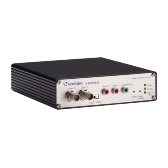
Ready LED is on. You successfully return to the default settings. Disk Full/Fault LED This LED is on, indicating the hard drive is full or faulty. This LED is on, indicating the GV-Video Server is ready for Ready LED connection. Power LED... -
Page 9: Rear View
A plug for inserting an Ethernet cable to build the network Ethernet Port connection. The connectors for digital inputs, relay outputs, RS±485, Wiegand Terminal Block interface, and the GPS module (only for GV-Video Server Hardware Version 2.0). Power In A plug for power input. Power Out... -
Page 10: Chapter 2 Getting Started
2.2 Assigning an IP Address Designed for use on an Ethernet network, the GV-Video Server must be assigned an IP address to make it accessible. Note: The GV-Video Server has a default address of 192.168.0.10. The computer used to... - Page 11 4. Select Static IP address. Type IP Address, Subnet Mask, Router/Gateway, Primary DNS and Secondary DNS in the Configure connection parameters section. 5. Click Apply. The GV-Video Server is accessible by entering the assigned IP address on the web browser.
-
Page 12: Configuration Basics
Getting Started 2.3 Configuration Basics Once the GV-Video Server is properly installed, the following important features can be configured using the browser-based configuration page and are discussed in the following sections in this manual: • Date and time adjustment: see 4.8.1 Date & Time Setting. -
Page 13: Chapter 3 Accessing The Gv-Video Server
Chapter 3 Accessing the GV-Video Server Two types of users are allowed to log in the GV-Video Server: Administrator and Guest. The Administrator has unrestricted access to all system configurations, while the Guest has the access to live images and network status only. -
Page 14: Functions Featured On The Main Page
Accessing the GV-Video Server 3.2 Functions Featured on the Main Page This section introduces the features of the Live View window and Network Status on the main page. The two features are accessible by both Administrator and Guest. Main Page of Guest Mode ▼... - Page 15 2 3 4 5 6 7 Figure 3-3 No. Name Function 1 Play Plays live video. 2 Stop Stop playing video. 3 Microphone Talks to the surveillance area from the local computer. 4 Speaker Listens to the audio around the camera. 5 Snapshot Takes a snapshot of live video.
-
Page 16: The Control Panel Of The Live View Window
Accessing the GV-Video Server 3.2.2 The Control Panel of the Live View Window To open the control panel of the Live View window, click the arrow button on top of the viewer. You can access the following functions by using the right and left arrow buttons on the control panel. -
Page 17: Snapshot Of A Live Video
3.2.3 Snapshot of a Live Video To take a snapshot of live video, follow these steps: 1. Click the Snapshot button (No. 5, Figure 3-3). The Save As dialog box appears. 2. Specify Save in, type the File name, and select JPEG or BMP as Save as Type. You may also choose whether to display the name and date stamps on the image. - Page 18 Accessing the GV-Video Server Picture-in-Picture View With the Picture in Picture (PIP) view, you can crop the video to get a close-up view or zoom in on the video. Navigation box Inset window Figure 3-5 1. Select PIP. An inset window appears.
- Page 19 Picture-and-Picture View With the Picture and Picture (PAP) view, you can create a split video effect with multiple close-up views on the image. A total of 7 close-up views can be defined. Figure 3-6 Select PAP. A row of three inset windows appears at the bottom. Draw a navigation box on the image, and this selected area is immediately reflected in one inset window.
-
Page 20: Alarm Notification
Accessing the GV-Video Server 3.2.6 Alarm Notification After input triggers and motion detection, you can be alerted by a pop-up live video and view up to four captured images. Captured images Pop-up live video Figure 3-7 To configure this function, click the Show System Menu button (No. 11, Figure 3-3), and select Alarm Notify. -
Page 21: Video And Audio Configuration
Auto Snapshot: The snapshot of live video is taken every 5 seconds on motion and input-triggered detection. File Path: Assigns a file path to save the snapshots. 3.2.7 Video and Audio Configuration You can enable the microphone and speaker for two-way audio communication and adjust the audio volume. -
Page 22: Camera Name Display
Accessing the GV-Video Server 3.2.9 Camera Name Display To display the camera name on the image, click the Show System Menu button (No. 11, Figure 3-3), and select Show Camera Name. 3.2.10 Image Enhancement To enhance the image quality of live video, click the Show System Menu button (No. 11, Figure 3-3), and select Image Enhance. -
Page 23: Ptz Control
3.2.11 PTZ Control To open the PTZ control panel, click the PTZ Control button (No. 9, Figure 3-3) and select PTZ Control Panel. Different PTZ devices have different functions, so the features included in the Option button may vary. This feature is only available when the PTZ is set ahead by the Administrator. For details, see 4.2.1 PTZ Settings. -
Page 24: Ptz Control
Accessing the GV-Video Server 3.2.12 Visual PTZ In additional to the PTZ control panel, you can display a visual PTZ control panel on the image. This feature is only available when the PTZ is set ahead by the Administrator. For details, see 4.2.1 PTZ Settings. -
Page 25: I/O Control
3.2.13 I/O Control The I/O Control window provides real-time graphic displays of camera and I/O status, and alarm events. Additionally, you can force output to be triggered. Figure 3-13 To display the I/O control window, click the I/O Control button (No. 8, Figure 3-3). The Alarm List is displayed in three levels. -
Page 26: Network Status
Accessing the GV-Video Server 3.2.14 Visual Automation The Visual Automation allows you to change the current state of the electronic device by simply clicking on its image, e.g. turning the light ON. This feature is only available when the Visual Automation is set ahead by the Administrator. For details, see 4.1.4 Visual Automation. -
Page 27: Visual Automation
Chapter 4 Administrator Mode The Administrator can access the system configuration via the Internet. Eight categories of configurations are involved in the system configuration: Video and Motion, Digital I/O and PTZ, Events and Alerts, Monitoring, Recording Schedule, Remote ViewLog, Network, and Management. ▼... -
Page 28: Video & Motion
Administrator Mode 4.1 Video & Motion This section includes the video image settings and how the images can be managed by using Motion Detection, Privacy Mask and Visual Automation. 4.1.1 Video Settings Figure 4-2... - Page 29 [Name] Rename the camera. The camera name will appear on the Live View. To display the camera name, see 3.2.9 Camera Name Display. [Connection Template] Select the type of your network connection. Unless you select Customized, this option will automatically bring up the recommended video resolution, frame rate, bandwidth and GOP size.
- Page 30 Administrator Mode VBR (Variable Bitrate): The quality of the video stream is kept as constant as possible at the cost of a varying bitrate. The bandwidth is much more efficiently used than a comparable CBR. Set the image quality to one of the 3 standards: Fair, Good, Excellent. CBR (Constant Bitrate): CBR is used to achieve a specific bitrate by varying the quality of the MPEG-4 stream.
-
Page 31: Motion Detection
4.1.2 Motion Detection Motion detection is used to generate an alarm whenever movement occurs in the video image. You can configure up to 8 areas with different sensitivity values for motion detection. Figure 4-3 1. The default sensitivity value is 2 for the whole area. To define a different sensitivity value, click Reset. -
Page 32: Privacy Mask
Administrator Mode 4.1.3 Privacy Mask The Privacy Mask can block out sensitive areas from view, covering the areas with dark boxes in both live view and recorded clips. This feature is ideal for locations with displays, keyboard sequences (e.g. passwords), and for anywhere else you don’t want sensitive information visible. -
Page 33: Visual Automation
4.1.4 Visual Automation This intuitive feature helps you automate any electronic device by triggering the connected output device. When you click on the image of the electronic device, you can simply change its current state, e.g. light ON. Figure 4-5 1. -
Page 34: Digital I/O & Ptz
Administrator Mode 4.2 Digital I/O & PTZ The I/O terminal block, on the rear panel of the GV-Video Server, has 16 pins for device control. These pins can be divided into four categories based on the interface being used: 1. Digital Input / Relay Output 2. -
Page 35: Input/Output Settings
4.2.2 Input/Output Settings The GV-Video Server can connect up to 4 input devices, e.g. sensors. Normal State: Set up the input state to trigger actions by selecting Open Circuit (N/O) or Grounded Circuit (N/C). Latch Mode: Enable the mode to have a momentary output alarm. - Page 36 To configure the input monitoring, see 4.4 Monitoring. For related PTZ settings, see 4.2.1 PTZ Settings. The GV-Video Server can connect up to 4 output devices, e.g. alarms. Select Enable to start the output device. Choose the output signal that mostly suits the device you are using: N/O (Open Circuit), N/C (Grounded Circuit), N/O Toggle, N/C Toggle, N/O Pulse and N/C Pulse.
-
Page 37: Gps/Wiegand
GV-System (DVR). Moreover, the Wiegand port can be used as an input to activate recording once the card reader is triggered. Note: The output format of Wiegand supported by the GV-Video Server is HID standard 26 bits and 37 bits. - Page 38 Send video to Center V2 and DVR when the Wiegand device is triggered: The selected camera(s) will start recording into GV-Video Server and the related video will also be sent to Center V2 and GV-System once the card reader is triggered.
- Page 39 Set GPS Update Period: Set the time in seconds for the update frequency of GPS data. After the GPS function is activated, you can view the location of the GV-Video Server on Google Maps. See 6.3 GPS Tracking. If the monitoring is also activated, the GPS tracking routes will be recorded along with videos.
-
Page 40: Events & Alerts
For e-mail and FTP alerts, it is required to start monitoring (See 4.4 Monitoring). Note: The Motion Detection function is an optional setting since it is activated by default. 4.3.1 E-mail After a trigger event, the GV-Video Server can send the e-mail to a remote user containing a captured still image. Figure 4-13 [Enable] Select to enable the e-mail function. -
Page 41: Ftp
Server Port: Type the SMTP Server’s port number. Or keep the default value 25. From email address: Type the sender’s e-mail address. Send to: Type the e-mail address(s) you want to send alerts to. Alerts Interval Time: Specify the interval between e-mail alerts. The interval can be between 0 and 60 minutes. - Page 42 Snapshot Resolution: Select D1 or CIF to be the resolution of snapshot images. [Act as FTP Server] Enable FTP access to the video server: The GV-Video Server acts as a FTP server, enabling users to download AVI files. Use alternative port: The default port is set to 21.
-
Page 43: Center V2
4.3.3 Center V2 After a motion or an I/O triggered event, the central monitoring station Center V2 can get notified by live videos and text alerts. For the live monitoring through Center V2, you must already have a subscriber account on Center V2. Note: To receive video alerts on input triggers, the Center V2 must use version 8.2 or later. - Page 44 1. Activate Link: Enable the monitoring through Center V2. 2. Host Name or IP Address: Type the host name or IP address of Center V2. 3. Port Number: Match the port to the GV-Video Server port on Center V2. Or keep the default value 5551.
-
Page 45: Vsm
4.3.4 VSM After a motion or an I/O triggered event, the central monitoring station VSM can get notified by text alerts. For the live monitoring through VSM, you must already have a subscriber account on VSM. Figure 4-16 To enable the VSM connection: 1. - Page 46 Administrator Mode 3. Port Number: Match the port to the GV-Video Server port on VSM. Or keep the default value 5609. 4. User Name: Type a valid user name to log into VSM. 5. Password: Type a valid password to log into VSM.
-
Page 47: Gv-Gis
4.3.5 GV-GIS Through the Internet connection, the GV-Video Server with enabled-GPS function can send GPS data and live video to the GV-GIS (Geographic Information System) for the services of vehicle tracking, location verification and live monitoring. Before you configure the GV-GIS connection on this setting page, the following conditions must be met: •... - Page 48 Administrator Mode 2. Host Name or IP Address: Type the host name or IP address of GV-GIS. 3. Port Number: Match the communication port on GV-GIS. Or keep the default value 3356. 4. User Name: Type a valid user name to log into GV-GIS. 5.
-
Page 49: Viewlog Server
4.3.6 ViewLog Server The ViewLog Server is designed for remote playback function. This server allows you to remotely access the recorded files saved at the GV-Video Server and play back video with the player ViewLog. Select Enable to activate the built-in server. Keep the default port 5552 or modify it if necessary. -
Page 50: Monitoring
Administrator Mode 4.4 Monitoring You can start recording manually, by schedule or by input trigger. Figure 4-20 [Manual] Manually activates motion detection and I/O monitoring. Select one of the following options and then click the Start button. Select all: Manually starts recording and I/O monitoring as well. Camera 1, Camera 2: Manually starts recording. -
Page 51: Recording Schedule
4.5 Recording Schedule The schedule is provided to activate recording and I/O monitoring on a specific time each day. 4.5.1 Recording Schedule Settings You can set up different monitoring schedules for each camera. Figure 4-21 Span 1- Span 3: Set a different recording mode for each time frame during the day. Each day can be divided into 3 time frames, represented by Span 1 to Span 3. -
Page 52: I/O Monitoring Settings
Server over TCP/IP network. For the first-time user, you need to install the Remote ViewLog program from the Software CD. For remote access to the GV-Video Server, the ViewLog Server built in the unit must be enabled. See 4.3.6 ViewLog Server. -
Page 53: Network
4.7 Network The Network section includes some basic but important network configurations that enable the GV-Video Server to be connected to a TCP/IP network. 4.7.1 LAN According to your network environment, select among Static IP, DHCP and PPPoE. Figure 4-23 [LAN Configuration] According to the network environment, select Wired or Wireless LAN. - Page 54 DHCP server, or you have obtained a domain name from the DDNS service provider that always links to the unit’s changing IP address. Static IP address: Assign a static IP or fixed IP to the GV-Video Server. Type the GV- Video Server’s TCP/IP and DNS parameters in the “Configure connection parameters”...
-
Page 55: Wireless-Client Mode
4.7.2 Wireless-Client Mode To use the wireless function, a wireless LAN USB adaptor is required. For supported wireless LAN adaptors, see Appendix A. Figure 4-24 Network type: Select the network mode Ad Hoc or Infrastructure. Infrastructure: Via the Access Point to connect to the Internet. This mode further gives wireless access to the Internet or data sharing under a previously wired environment. - Page 56 Administrator Mode WEP (Wired Equivalent Privacy): A type of data encryption. Type up to four WEP Keys in HEX or ASCII format. Note that if you use HEX format, only digits 0-9 and letters A-F, a-f are valid. WPAPSK-TKIP and WPA2PSK-TKIP: Type WPA-PSK (Pre-Shared Key) for data encryption.
-
Page 57: Advanced Tcp/Ip
4.7.3 Advanced TCP/IP This section introduces the advanced TCP/IP settings, including DDNS Server, HTTP port, streaming port and UPnP. Figure 4-25 [Dynamic DNS Server Settings] DDNS (Dynamic Domain Name System) provides a convenient way of accessing the GV- Video Server when using a dynamic IP. DDNS assigns a domain name to the GV-Video Server, so that the Administrator does not need to go through the trouble of checking if the IP address assigned by DHCP Server or ISP (in xDSL connection) has changed. - Page 58 2. Service Provider: Select the DDNS service provider you have registered with. 3. Host Name: Type the host name used to link to the GV-Video Server. For the users of GeoVision DDNS Server, it is unnecessary to fill the field because the system will detect the host name automatically.
-
Page 59: Umts
IP Address: The IP address of the GV-Video Server will be displayed after enabling the UMTS service. The next time when you want to log in the GV-Video Server, you need to enter the IP address into your browser. If you use the UMTS connection with dynamic IP addresses, first use the DDNS function to get a domain name linking to the GV-Video Server’s changing IP address. -
Page 60: Ip Filter
The GV-Video Server will rebuild the connection if disconnection is detected. 4.7.5 IP Filter The Administrator can set IP filtering to restrict access to the GV-Video Server. Figure 4-27 To enable the IP Filter function: 1. Enable IP Filtering: Enable the IP Filtering function. -
Page 61: Management
4.8 Management The Management section includes the settings of data and time, USB mass storage device and user account. Also you can view the firmware version and execute certain system operations. 4.8.1 Date & Time Setting The date and time settings are used for date and time stamps on the image. Figure 4-28... - Page 62 IP setting to the timeserver of interest. [Synchronized with your computer or manually] Manually changes the GV-Video Server’s date and time. Or, synchronize the GV-Video Server’s date and time with those of the local computer.
-
Page 63: Gps Maps Settings
Then, enter the registered Maps API Key, the longitude and latitude of the GV-Video Server, and location name to enable this function. If your GV-Video Server is installed on an active vehicle, it is not necessary to enter Default Longitude and Default Latitude, since the vehicle location will be traced by GPS. -
Page 64: Storage Settings
Administrator Mode 4.8.3 Storage Settings Based on Linux ext3 file system, the GV-Video Server supports external USB mass storage devices for video and audio recording. Normally USB mass storage devices are ready for Windows OS. Therefore, you need to format the devices by using the following Storage Settings. - Page 65 This section shows the partition details of the attached storage devices. To add a USB mass storage device: 1. Attach the device to the GV-Video Server. 2. Click the Format button. After the format is complete, the partition information will display. The maximum space for one partition is 200 GB.
-
Page 66: Iscsi Storage Settings
Administrator Mode 4.8.4 iSCSI Storage Settings You can record files of the GV-Video Server to the iSCSI storage system over the Internet. Enter the Initiator node name created on the iSCSI storage system, activate the link, and type the IP address of iSCSI data port 1 and port 2 to enable connecting the iSCSI storage system to the GV-Video Server. -
Page 67: User Account
4.8.5 User Account You can change the login name and password of Administrator, Guest and FTP Server User. • The default Administrator login name and password are admin. • The default Guest login name and password are guest. To allow a Guest user log in without entering name and password, select Disable Check Login Guest Identity. -
Page 68: Tools
Server’s network setting again. [Reboot] Clicking the Reboot button will make the GV-Video Server perform the software reset. The Ready LED on the front panel will turn off. Wait until the Ready LED turns on and re-log in the server. -
Page 69: Chapter 5 Recording And Playback
5. If you want the recording to be triggered by input device, configure the operation of I/O devices. See 4.2.2 Input / Output Settings. 6. To start recording and I/O monitoring, see 4.4 Monitoring. The GV-Video Server will start recording in case of motion detection, I/O trigger, or during the scheduled time. 5.2 Playback Two methods are available to play back the video files recorded at the GV-Video Server: •... -
Page 70: Playback Using Usb Mass Storage Device
Recording and Playback 5.2.1 Playback Using USB Mass Storage Device You can play back the files recorded at the GV-Video Server by attaching the USB mass storage device to the GV-System. However, the GV-System is run on Windows system while the files recorded at GV-Video Server is on Linux system. To enable Windows to recognize the files, you need to install the program Ext2 Installable File System included in the Software CD. -
Page 71: Playback Using Remote Viewlog
GV-Video Server’s web interface. 2. When this dialog box appears, type the GV-Video Server’s IP address, login ID and password. Keep the default port 5552 or modify it if necessary. -
Page 72: Playback Of Gps Tracking Routes
1. The GV-Video Server must allow the remote access with ViewLog Server activated. See 4.3.6 ViewLog Server. 2. To remotely connect to GV-Video Server from GV-System, click the Tools button and select Remote ViewLog Service. The Connect to Remote ViewLog Service dialog box appears. - Page 73 6. To play back tracking routes, click the Tools button and select GPS Display Window. The first-time user will be prompted for a License Agreement. Read through the license terms before you click I understand and agree to continue. 7. Select the events of tracking routes from the Video Events list, select the desired video mode, and click the Play button to start.
-
Page 74: Playback Of Daylight Saving Time Events
5.2.4 Playback of Daylight Saving Time Events On GV-System, you can retrieve the events recorded during the Daylight Saving Time (DST) period from GV-Video Server for playback. You can also attach the USB mass storage device with the recorded files to GV-System for playback. -
Page 75: Chapter 6 Advanced Applications
6.1 Upgrading System Firmware GeoVision will periodically release the updated firmware on the website. The new firmware can be simply loaded into the GV-Video Server over the Internet or by using the Video Server Utility included in the Software CD. -
Page 76: Advanced Applications
3. Click the Search button to locate the available GV-Video Servers on the same LAN. Or click the New button and assign the IP address to locate a GV-Video Server over the Internet. Or highlight one GV-Video Server in the list and click the Delete button to remove it. -
Page 77: Backing Up And Restoring Settings
6.2 Backing Up and Restoring Settings With the IP Device Utility included in the Software CD, you can back up the configurations in the GV-Video Server, and restore the backup data to the current unit or import it to another unit. - Page 78 Advanced Applications 3. Click the Export Settings button. This dialog box appears. Figure 6-5 4. Click the Browse button to assign a file path. 5. Type Password, and click Export Settings to save the backup file. To restore the settings: 1.
-
Page 79: Gps Tracking
6.3 GPS Tracking The GV-Video Server Hardware Version 2.0 supports the Global Position System (GPS) for active vehicle tracking and location verification. The vehicle location will be tracked by Google Maps. To track the location of your GV-Video Server: 1. Connect the GV-GPS module or any GPS module supporting UART interface to the I/O terminal block on the rear panel of the unit. - Page 80 Advanced Applications 5. To track the GV-Video Server on maps, click Open. A warning message appears. Figure 6-8 6. Right-click the warning message and select Allow Blocked Content. The map will be displayed. The icon indicates the location of your GV-Video Server. At the upper right corner you have options for viewing different map formats, such as Satellite and Hybrid.
-
Page 81: Chapter 7 Dvr Configurations
System connects to one GV-Video Sever, it takes up to 4 connections. When users connect to one GV-Video Server via browser, it takes up to 2 connections. When users operate the Camera/Audio Control on Center V2, it takes 1 connection. -
Page 82: Setting Up Ip Cameras
DVR Configurations 7.1 Setting up IP Cameras To set up IP cameras on the GV-System, follow these steps: On the main screen, click the Configure button, select General Setting, select Camera / Audio Install and click IP Camera Install. This dialog box appears. Figure 7-2 Check Install IP Camera, and select the number of IP Cameras you want to link to, and click Configure. - Page 83 Figure 7-5 In the Network Type section, select your network environment WAN or LAN. Click Query to detect the GV-Video Server. When it is detected, its available camera options will be displayed in the Camera List section. Select the camera for live view from the Preview drop-down list, and the camera for recording from the Record drop-down list.
- Page 84 Gain Control: Increase or decrease the gain of the microphone. Wave Out: Select this option to listen to live audio from the GV-Video Server. Rec Audio: Select this option to activate the audio recording.
-
Page 85: Receiving Cardholder Data From Video Server
30, there is only one key frame among 30 frames. For the GOP setting, see 4.1.1 Video Settings. 7.2 Receiving Cardholder Data from Video Server Over the network, GV-System can receive cardholder data from the Wiegand-interface card reader. This transmission is made possible through GV-Video Server. Wiegand In Video Data Text Data... - Page 86 Click the New button. This dialog box appears. Figure 7-9 Select GV-Video Server from the Type drop-down list, enter a descriptive name for the Video Server, select the IP address of the video server from the Address drop- down list, and then select the camera to be mapped with.
-
Page 87: Remote Monitoring With Multi View
5. To create a host, click the New button. You need to create a group before creating a host. 6. Select GV-Video Server from the Device drop-down list. Type the host name, IP address, user name and password of the GV-Video Server. Modify the default VSS... - Page 88 DVR Configurations Figure 7-11 4. Click Save to establish connection. For details on the Multi View functions, see “Multi View MPEG 4 Encoder Viewer”, Viewing Live Video Using WebCam, User’s Manual on the Surveillance System Software CD.
-
Page 89: Remote Monitoring With E-Map
Figure 7-12 6. Give the GV-Video Server a location name, and type its IP address (or domain name). Keep the default VSS port as 10000, or modify it to match that of GV-Video Server. 7. Click OK to save the settings. - Page 90 Download page. Install the E-Map program before you can run it. 4. On the Remote E-Map window, click the Login button and select the GV-Video Server host to access its videos and I/O devices. The valid user name and password are required to log in the GV-Video Server.
-
Page 91: Remote Monitoring With Mobile Phones
7.5 Remote Monitoring with Mobile Phones Using a PDA, Smartphone and 3G-enabled mobile phone, you can receive live video streaming from the GV-Video Server. The list below is the GV mobile applications supporting the GV-Video Server. Handheld Settings OS Supported... - Page 92 The following is the example of connecting the PDA based on Windows Mobile 5.0 to the GV-Video Server. 1. The GV-Video Server needs to allow the remote access from the mobile phone user first. On the main page, select Video and Motion, click Video Settings and select the desired camera.
-
Page 93: Chapter 8 Cms Configurations
Chapter 8 CMS Configurations This section introduces the related settings to enable connecting to the GV-Video Server in the central monitoring stations Center V2, VSM and Dispatch Server. 8.1 Center V2 The Center V2 can monitor and manage the cameras and I/O devices connected to the GV-Video Server. - Page 94 GV-Video Server, is triggered. For the related Wiegand settings on the GV-Video Server, see 4.2.3 Wiegand Port. For further information on how to mange the received video from the GV-Video Server, see GV-CMS Series User’s manual.
-
Page 95: Vsm
GV-Video Server Figure 8-4 To set the appropriate port connecting to the GV-Video Server, click Configure on the window menu, and select System Configure to display this dialog box. Under the Connective Port for Video Server item, keep the default port 5609, or modify it to match the VSM port on the GV-Video Server. -
Page 96: Dispatch Server
To enable connecting to the GV-Video Server, click the Server Setting button on the toolbar, and enable Allow Video Server Login as Subscriber from Port. Keep the default port as 5551, or modify it to match the Center V2 port on the GV-Video Server. Figure 8-7 For further information on how to mange the received video from the GV-Video Server, see GV-CMS Series User’s manual. -
Page 97: Chapter 9 The I/O Terminal Block
Chapter 9 The I/O Terminal Block The 16-pin terminal block, located on the rear panel, provides the interface to: four digital inputs, four relay outputs, an RS-485 interface, a Wiegand interface and auxiliary power. The I/O terminal block can be used to develop applications for motion detection, event alerts via E-mail and FTP, center monitoring by Center V2 and VSM, PTZ control, Wiegand-interface card reader and a variety of other functions. -
Page 98: Relay Output
The relay outputs on the terminal block can only drive a maximum load of 5V. Working in conjunction with the GV-Relay V2 module, it can drive heavier loads. Refer to the figure and table below to connect the GV-Relay V2 module to the GV-Video Server. Output Devices 1-4... -
Page 99: Specifications
Specifications Video Model GV-VS01 GV-VS02 Video Standard NTSC, PAL 1 channel 2 channels Video Input Compression Geo MPEG4 (ASP) NTSC 30 fps at Full D1 resolution Frame Rate 25 fps at Full D1 resolution Full D1, Half D1, CIF, QCIF Resolution Configurable frame rate and bandwidth, Video Streaming... - Page 100 Specifications Network 10/100 Base-T Ethernet, Interface 802.11b/g Wireless LAN (optional) HTTP, TCP, UDP, SMTP, FTP, DHCP, NTP, UPnP, Protocol DynDNS Connector Video Input BNC 2 ports Audio Input RCA 2 ports Audio Output RCA 1 port 4 digital inputs, 4 relay outputs, RS±485, Terminal Block 1 Wiegand interface, 1 UART interface Ethernet...
-
Page 101: Appendix
Appendix A. Supported Wireless LAN USB Adaptor Vendor Model EDIMAX EW-7318Ug D-Link DWL-G122 C1 version Linksys WUSB54GC B. Supported UMTS Module Vendor Model Option GlobeSurfer iCON (Vodafone) GlobeSurfer iCON 7.2 HUAWEI E220...
Need help?
Do you have a question about the GV-Video Server and is the answer not in the manual?
Questions and answers