Table of Contents
Advertisement
Quick Links
Advertisement
Table of Contents

Related Manuals for GeoVision GV-Tower System V2


Summary of Contents for GeoVision GV-Tower System V2
- Page 1 GV-Tower System V2 (Rev. C) User’s Manual TowerV2C-UM-A...
- Page 2 Every effort has been made to ensure that the information in this manual is accurate. GeoVision, Inc. makes no expressed or implied warranty of any kind and assumes no responsibility for errors or omissions. No liability is assumed for incidental or consequential damages arising from the use of the information or products contained herein.
- Page 3 User’s Manual for GV-Tower System V2 (Rev. C) Welcome to the GV-Tower NVR/VMS System V2 (Rev. C) User’s Manual. The Manual provides an overview of GV-Tower NVR/VMS System V2 (Rev. C) and its accessories. It also includes the instructions to guide you through the installation and use of GV-Tower NVR/VMS System V2 (Rev.
-
Page 4: Table Of Contents
3.9.1 Activating Two Monitors ..............27 3.9.2 Setting Live View................28 3.9.3 Setting Scanned Pages..............29 3.9.4 Setting Pop-up Alert ..............30 3.9.5 Setting Live View with Pop-up Alert..........32 3.10 System Restoration..................33 3.11 Updating GV-Tower System V2 (Rev. C)..........34 Chapter 4 Troubleshooting ..................35... - Page 5 Specifications ......................39 Appendix…......................42 A Hard Disk Requirements................42 B Total Frame Rate and Max. No. of Channels Supported ......42 C Supported IP Devices...................45 D Supported Hard Disk Drive................46 Warranty Requirements ..................47 Warranty Form ......................48...
-
Page 6: Safety Instructions
Safety Instructions Observe these safety instructions to help ensure against injury to yourself and damage to the product. Read all safety and installation instructions before you operate the product. Do not operate the product in high humidity areas or expose it to water or moisture. ... -
Page 7: Chapter 1 Introduction
Introduction Chapter 1 Introduction 1.1 Features Powered by Intel Core i5 Processor 64-bit Windows 10 IoT Enterprise Support for GPU Decoding 4-bay hot swap data HDD Maximum storage capacity of 56 TB Pre-installed SSD for recovery ... -
Page 8: Model
GV-Tower NVR/VMS System V2 (Rev. C) has the following models: - 32-channel digital video recorder GV-Tower NVR - 32-channel of free GeoVision IP devices, or 32-channel combination of System V2 (Rev. C) GeoVision IP devices and third-party IP devices digital video recorder... -
Page 9: Packing List
Introduction 1.4 Packing List The GV-Tower NVR/VMS System V2 (Rev. C) package includes the following items. If any of the items are missing or damaged, contact your dealer to arrange a replacement. Important: Please keep the original carton and all packing materials for future shipping need. ... -
Page 10: Recommended Hard Drive
1.5 Recommended Hard Drive For system efficiency, we recommend the following enterprise level hard disk drives. Avoid using desktop level or green HDD which may affect system efficiency. For details, see Appendix D. Certified Hard Disk Drive. Seagate Enterprise Series ... -
Page 11: Chapter 2 Overview
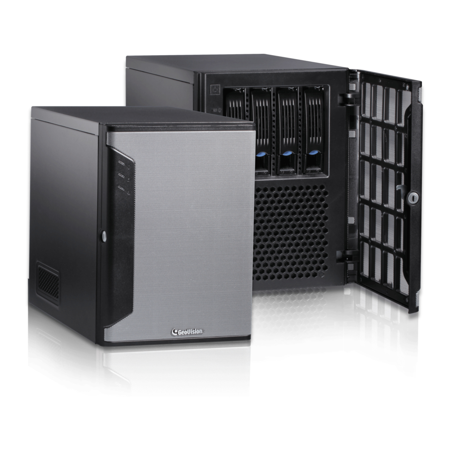
Overview Chapter 2 Overview 2.1 Front View Figure 2-1 No. Name Name 3.5” HDD Tray x 4 Not Functional Power Button Reset Button Power LED (Blue) USB (3.1 Gen 1) x 2 HDD Activity LED (Red) -
Page 12: Rear View
2.2 Rear View Figure 2-2 No. Name Name Power Connector HDMI Port x 1 Audio Line In Port / Out Port VGA Port x 1 Audio Microphone In Port DVI-D Port x 1 Ethernet Port x 1 PS/2 keyboard / mouse port USB (3.1 Gen 1) Port x 2 USB 2.0 Port x 2... -
Page 13: Chapter 3 Getting Started
Getting Started Chapter 3 Getting Started 3.1 Basic Installation This section describes all the equipment required to program and operate GV-Tower NVR/VMS System V2 (Rev. C). Here we use GV-Tower NVR System V2 (Rev. C) as the example. Figure 3-1 Connect an HDTV to GV-Tower NVR/VMS System V2 (Rev. -
Page 14: Using The Dual Display
3.1.1 Using the dual display You can connect to any two of the three video outputs on the back panel of the GV-Tower NVR/VMS System V2 (Rev. C). Figure 3-2 3.1.2 Using the IR Remote Control The optional GV-IR Remote Control provides easy control of GV-Tower NVR/VMS System V2 (Rev. -
Page 15: Installing The Hard Drive
Getting Started 3.2 Installing the Hard Drive GV-Tower NVR/VMS System V2 (Rev. C) uses SATA hard drives for video and audio data storage. Before recording, ensure to install your hard drives. Follow the below steps to install the hard drive. 1. - Page 16 4. Insert the hard drive in the drawer. Figure 3-6 5. Secure the hard drive with the 4 screws, and make sure all screw heads flush with the surface. Figure 3-7 6. Put the drawer back in the drive bay of GV-Tower NVR/VMS System V2 (Rev. C), and push the latch until it locks.
-
Page 17: Starting Up Windows
Getting Started 3.3 Starting up Windows The Windows setup is preparing your computer for first use. 1. After the Windows starts, this setup screen appears. Select your language and click Next to continue. Figure 3-9 2. Select your regional settings and time zone and click Next to continue. Figure 3-10... - Page 18 3. Click Accept to accept Microsoft software license terms. 4. Select between “Customize” or “Use Express settings” for your Windows 10 installation. 5. Type your account name. It is recommended that you create a password for your account and click Next . Figure 3-11 When the above setup process is complete, Windows will finalize your settings automatically in the background and restart.
-
Page 19: Formatting The Hard Drive
Getting Started 3.4 Formatting the Hard Drive After installing hard drives to your system, you will need to format them before use. 1. Right-click the Computer icon on your desktop, select Manage, and select Disk Management when the Computer Management window appears. 2. - Page 20 4. The New Simple Volume Wizard appears. Click Next to continue. Figure 3-11 5. The default partition size is the same as the maximum disk space. Make changes if necessary. Click Next to continue. Figure 3-12...
- Page 21 Getting Started 6. Assign a drive path that is not in use by other devices, and click Next to continue. Figure 3-13 Note: The default drive path starts from D:\. 7. Type a name in the Volume label box, ex. HDD1, and click Next to continue. Figure 3-14...
- Page 22 8. When the formatting is complete, click Finish to close the wizard. Figure 3-15 9. When the drive is successfully initialized, partitioned, and formatted, its status description should display “Healthy.” Figure 3-16...
-
Page 23: Gv-Tower Nvr System V2 (Rev. C)
Getting Started 3.5 Adding the Hard Drive to the Recording Path For GV-Tower NVR/VMS System V2 (Rev. C), you need to add the formatted hard drives to the recording path before recording. 3.5.1 GV-Tower NVR System V2 (Rev. C) 1. Click the Windows Start button, click GV-NVR, and select Hot Swap HDD Tool. The MediaMan Tools window appears. - Page 24 3. If a hard drive is not inserted, follow these steps: A. Insert a hard drive or plug a USB hard drive to GV-Tower NVR System V2 (Rev. C). Figure 3-18 B. Select Add to recording path, and select the storage group from the drop-down list. Note: Storage 1 is the default storage group.
-
Page 25: Gv-Tower Vms System V2 (Rev. C)
Getting Started 3.5.2 GV-Tower VMS System V2 (Rev. C) 1. On GV-VMS, click Home , select Toolbar , select Configure , select System Configure, and click Record Setting. This dialog box appears. Figure 3-20 2. Click the Arrow button next to Storage. This dialog box appears. Figure 3-21... - Page 26 3. To add a hard drive to the recording path, follow these steps: Figure 3-22 A. To add a new folder in the first storage group, click the Add button on the right pane and select a folder. Only 1 folder can be assigned as storage folder for each partition (e.g.
-
Page 27: Setting Up On-Screen Led Panel
Getting Started 3.6 Setting Up On-Screen LED Panel For GV-Tower NVR/VMS System V2, a LED panel on the screen provides a quick indication of the activity status of hard disk drives. Figure 3-23 LED Color Description - No HDD is assigned to this LED. Gray - The system is not started. - Page 28 LED Panel always stays on top: This option makes the LED panel stay on top of other windows when the Media Man Tools window is minimized. Synchronize the LED Panel with the LED Device on GV-Tower System V2: Not functional on GV-Tower NVR/VMS System V2. ...
-
Page 29: Replacing The Hard Drive
Getting Started 3.7 Replacing the Hard Drive You can replace the hard drive without shutting down GV-Tower NVR/VMS System V2 (Rev. 1. Do not turn off the power before you replace the hard drive. 2. Push the release latch. The drawer handle pops up. 3. -
Page 30: Twin View Display
3.8 Twin View Display 3.8.1 GV-Tower NVR System V2 (Rev. C) You can display live view and play back video in two separated monitors. 1. Click the Search button on your desktop, type Control Panel and press Enter key to open Control Panel. - Page 31 Getting Started 8. lick the Up button on the toolbar, go to the system folder and locate DMPOS.exe. Figure 3-26 9. Double-click DMPOS.exe. The Set Application Function Position dialog box appears. Figure 3-27 10. In the Screen Setup tab, select TwinView from the Displayer Mode drop-down list. 11.
-
Page 32: Gv-Tower Vms System V2 (Rev. C)
3.8.2 GV-Tower VMS System V2 (Rev. C) You can customize the display settings of GV-VMS. Click Home , select Toolbar select Configure , select System Configure, and click Set Position. This dialog box appears. The right side of the dialog box is only available when multiple monitors are installed. Figure 3-28 Select Monitor: If you have multiple monitors connected, select the monitor you want to ... -
Page 33: Digital Matrix
Getting Started 3.9 Digital Matrix To display multiple channels through two monitors, Digital Matrix is thus introduced to provide a method. The Digital Matrix includes these features: Live view: You can set different live views and screen divisions for each monitor. ... -
Page 34: Setting Live View
3.9.2 Setting Live View You can set different live views and screen divisions for each monitor. 1. On the main screen, click the Configure button, click Accessories, and select Digital Matrix Setting. This dialog box appears. Figure 3-30 2. Use the Display list to select the monitor to be configured. 3. -
Page 35: Setting Scanned
Getting Started 3.9.3 Setting Scanned Pages You can set up to 16 scanned pages with different screen divisions and channels for each monitor. 1. Use the Display list to select the monitor to be configured. 2. In the upper-left column, expand the Matrix folder tree, and click Page 1. This page appears. -
Page 36: Setting Pop-Up Alert
3.9.4 Setting Pop-up Alert You can be alerted by pop-up live videos when motion is detected or I/O devices are triggered. 1. Use the Display list to select the monitor to be configured. 2. In the upper-left column, click Event Popup. This page appears. Figure 3-32 ... - Page 37 Getting Started 3.9.4.1 Setting Pop-up Positions When you select Random Position of Camera, you can decide the positions for pop-up cameras. Fixed Position of Camera: The cameras pop up in their assigned positions. To assign positions, select Screen Division. Then drag and drop the cameras number to the desired potions on the divisions.
-
Page 38: Setting Live View With Pop-Up Alert
3.9.5 Setting Live View with Pop-up Alert You can set a different live view mode with pop-up alert together for each monitor. When alert events occur, the live video of the associated camera will pop up on the assigned monitor to replace its live view mode. -
Page 39: System Restoration
Getting Started 3.10 System Restoration You can restore preinstalled files once they are damaged by running the recovery from the hidden partition. To restore the operating system and all preinstalled software, follow the steps below. Note: After recovery, you need to re-install all settings and passwords. But the recovery will not delete your recording files saved on the GV-Tower NVR/VMS System V2 (Rev. -
Page 40: Updating Gv-Tower System V2 (Rev. C)
8. Once the restoration is complete, click Finish to leave the recovery system and restart the Windows automatically. 3.11 Updating GV-Tower System V2 (Rev. C) If you like to update your GV-Tower NVR/VMS System V2 (Rev. C), contact your dealer for more information. -
Page 41: Chapter 4 Troubleshooting
Troubleshooting Chapter 4 Troubleshooting GV-Tower NVR/VMS System V2 (Rev. C) stops responding (aka “crashed” or “froze”). If your GV-Tower NVR/VMS System V2 (Rev. C) is not responding to your clicking, typing, or mouse movements, try these steps to get your GV-Tower NVR/VMS System V2 (Rev. C) back on track. - Page 42 GV-Tower NVR/VMS System V2 (Rev. C) hard disk corrupts. If you are experiencing file system corruption problems, such as lost clusters, cross-linked files or invalid files or directories, try these steps: 1. Use the HD Tune utility to scan the hard disk for errors. Follow these steps: A.
- Page 43 Troubleshooting 2. If the HD Tune utility does not find any defects, use the Windows built-in utility to attempt to fix the errors. Follow these steps: A. Right-click the Computer icon on your desktop, select Manage, and select Disk Management. B.
- Page 44 Try to replace a camera or camera cable to see if this fixes the problem. How can I find more help? 1. Visit our website at http://www.geovision.com.tw/ 2. Write us at support@geovision.com.tw...
-
Page 45: Specifications
Specifications GV-Tower NVR/VMS System V2 (Rev. C) Hardware System Intel Core i5 Processor 8 GB Dual Channels 4 (3.5” HDD) No. of HDD 64 GB SSD Internal Storage 64-bit Windows 10 IoT Enterprise DirectX 300 W, 110-115 V, 60 Hz Power 300 W, 220-230 V, 50 Hz RJ-45, 10 / 100 / 1000 Mbps x 1... - Page 46 32 channels in increments of 1 channel Audio Input 32 channels (license required) Note: It is required to enable the dual-stream function on GeoVision and third-party IP cameras to have the maximum number of channels supported. Live View and Playback Image Control Contrast / Brightness / Saturation / Hue Round the Clock / Motion Detection / Sensor Detection / Pre &...
- Page 47 Specifications Network Type LAN, WAN, Internet System Monitoring and Recovery Power Restoration Automatic restart after power outage Two independent Watchdogs Monitoring (Hardware Watchdog + Software Watchdog) Automatic system rebuild from internal SSD. Recovery Language GV-Tower NVR System V2 GV-Tower VMS System V2 Model (Rev.
-
Page 48: Appendix
Appendix A. Hard Disk Requirements The total of recording frame rates that you can assign to a single hard disk is listed as below: Frame rate limit in a single hard disk when connecting to IP cameras Frame Rate Limit in a Single Hard Disk H.264 H.265 MJPEG... - Page 49 Appendix Note: The total frame rate and channels supported are determined in round-the-clock recording settings with live view only, while remote connections and video analysis features being disabled. NVR System For GV-IP Camera (Dual Stream) Intel Core i5 Video Stream 2 Stream 1 (H.264) Mbps Mbps...
- Page 50 VMS System For GV-IP Camera (Dual Stream) Intel Core i5 Video Stream 2 Stream 1 (H.264) Mbps Mbps Max. FPS Total Full-Frame Resolution (H.264) Channels 1.3 MP 1280 x 720 3.99 640 x 360 1.99 30 fps 960 fps 32 ch 2 MP 1920 x 1080 6.12...
-
Page 51: C Supported Ip Devices
Appendix C. Supported IP Devices This list provides the supported IP device brands. For detailed information on the supported IP devices, refer to Supported IP Camera List on GeoVision’s Website: http://www.geovision.com.tw/_upload/files/support_list.pdf GeoVision ACTi Arecont Vision AXIS Bosch Canon D-Link Etrovision... -
Page 52: D Supported Hard Disk Drive
D. Certified Hard Disk Drive This following hard disk drive models are certified by Geovision to be compatible with GV-Tower NVR/VMS System V2 (Rev. C). Model Capacity WD1002F9YZ 1 TB WD1003FBYZ 1 TB WD1005FBYZ 1 TB HUS722T1TALA604 1 TB HUS722T2TALA604... -
Page 53: Warranty Requirements
Warranty Form Warranty Requirements Thank you for purchasing the GV-Tower NVR / VMS System V2 (Rev. C). GeoVision understands that accident happen, and have developed a warranty policy in place. See http://www.geovision.com.tw/warranty.php for more information on warranty. Before you return the product Some problems you experience may be related to software or the operating system. - Page 54 2. Securely pack the product in its original carton using the original packing material, or in equivalent packaging. 3. The product shall be returned to GeoVision, Taiwan at your expense for shipping and insurance costs. BEFORE YOU DELIVER YOUR GV-TOWER NVR/VMS V2 SYSTEM FOR WARRANTY SERVICE, IT IS YOUR RESPONSIBILITY TO BACK UP YOUR DATA.
Need help?
Do you have a question about the GV-Tower System V2 and is the answer not in the manual?
Questions and answers