GeoVision GV-Video GV-VS04H User Manual
Hide thumbs
Also See for GV-Video GV-VS04H:
- User manual (185 pages) ,
- Quick start manual (13 pages) ,
- How-to manual (15 pages)

Related Manuals for GeoVision GV-Video GV-VS04H


Summary of Contents for GeoVision GV-Video GV-VS04H
- Page 1 GV-Video Server User's Manual Before attempting to connect or operate this product, please read these instructions carefully and save this manual for future use. VS04H.VS12V106.VS11V102.VS14V10-A...
- Page 2 GeoVision. Every effort has been made to ensure that the information in this manual is accurate. GeoVision, Inc. makes no expressed or implied warranty of any kind and assumes no responsibility for errors or omissions. No liability is assumed for incidental or consequential damages arising from the use of the information or products contained herein.
-
Page 4: Chapter 1 Introduction
Chapter 1 Introduction The GV-Video Server, including the models GV-VS04H, GV-VS11, GV-VS12 and GV- VS14, allows the conversion of any analog camera into a fully functional IP camera. It streams the real-time digital video over the Internet in the same way that current IP cameras do. -
Page 5: Packing List
1.2 Packing List 1.2.1 GV-VS04H / GV-VS14 1. AC Power Cord x 1 2. DC Male-to-Male Cable (for powering on the camera through GV-Video Server) x 1 3. Power Adaptor x 1 4. Wall Hook x 1 5. Conical Anchor x 4 6. - Page 6 Introduction 1.2.3 GV-VS12 1. AC Power Cord x 1 2. Power Adaptor x 1 3. I/O Cable with RJ-45 Connector x 1 4. Wall Hook x 1 5. Conical Anchor x 4 6. Screw x 4 7. Sticker (for positioning conical anchors) x 1 Figure 1-3 8.
-
Page 7: System Requirement
1.3 System Requirement To access the Web interface of the GV-Video Server, it is required to use Microsoft Internet Explorer 7.x or later. Note: For the users of Internet Explorer 8, additional settings are required. For details, see Appendix A. 1.4 PoE Support The models supporting PoE (Power over Ethernet) include: •... - Page 8 Introduction 1.6 Options Optional devices can expand your GV-Video Server’s capabilities and versatility. Contact your dealer for more information. The GV-GPS Receiver is a Global Position System receiver. With the GV-GPS Receiver, you can perform GPS GV-GPS Receiver tracking and location verification of the GV-Video Server. Two types of interfaces are available: UART (for GV- VS04H/GV-VS14) and RS-232 (for GV-VS12).
-
Page 9: Physical Description
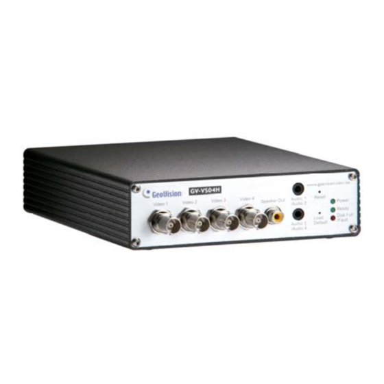
1.7 Physical Description This section identifies the various components of the GV-Video Server. 1.7.1 Front View 1.7.1.1 GV-VS04H / GV-VS14 Figure 1-4... - Page 10 Introduction No. Name Function Video Input 4 plugs for video inputs. Speaker Output A plug for the speaker device. Audio Input Each plug is for 2 audio inputs. It reboots the GV-Video Server, and keeps all current Reset configurations. It resets all configurations to their factory settings. See 6.4 Default Button Restoring to Factory Default Settings.
- Page 11 1.7.1.3 GV-VS11 Figure 1-5 No. Name Function Video Input 1 plug for video input. It resets all configurations to their factory settings. See 6.4 Default Button Restoring to Factory Default Settings. Audio Input 1 plug for audio input. This LED is on, indicating the GV-Video Server is ready for Ready LED connection.
-
Page 12: Rear View
Introduction 1.7.2 Rear View 1.7.2.2 GV-VS04H / GV-VS14 Figure 1-7 No. Name Function USB Port 2 USB ports for installing portable storage devices. The connectors for digital input, relay output, PTZ camera, Terminal Block Wiegand device and GPS module control. See Chapter 9 Auxiliary Device Connectors. - Page 13 1.7.2.3 GV-VS11 Figure 1-8 No. Name Function USB Port 1 USB port for installing portable storage device. A plug for inserting an Ethernet cable to build the network Ethernet Port connection. The connectors for digital input, digital output and PTZ camera Terminal Block control.
-
Page 14: Chapter 2 Getting Started
Getting Started Chapter 2 Getting Started This section provides basic information to get the GV-Video Server working on the network. 2.1 Installing on a Network These instructions describe the basic connections to install the GV-Video Server on the network. Here we use GV-VS04H as the example to demonstrate the steps. Figure 2-1 1. - Page 15 Note: 1. The GV-VS11 does not support PoE function. 2. The DC Male-to-Male Cable and 3.5 mm Stereo to RCA Cable are only supplied for GV-VS04H and GV-VS14. 3. The GV-Video Server cannot work with the microphone requiring power from the unit. Use the microphone that has external power supply.
-
Page 16: Checking The Ip Address
Getting Started 2.2 Checking the IP Address By default, an unused IP address is automatically assigned by the DHCP server to the GV-Video Server when connecting to the network. Follow the steps below to look up the IP address and access the Web interface. Install the GV-IP Device Utility program included on the Software CD/DVD. -
Page 17: Changing The Ip Address
In this case, it is strongly suggested to modify the IP address to avoid the IP address conflict with other GeoVision IP device on the same LAN. Open your Web browser, and type the IP address of the GV-Video Server or the default IP address http://192.168.0.10... -
Page 18: Configuration Basics
Getting Started IMPORTANT: • PPPoE should only be enabled if you know which IP address the GV-Video Server will get from the ISP. Otherwise, you must use the Dynamic DNS service to obtain a domain name linked to the GV-Video Server’s changing IP address first. -
Page 19: Chapter 3 Accessing The Gv-Video Server
4. A video image, similar to the example in Figure 3-2, is now displayed in your browser. Note: To enable the updating of images in Microsoft Internet Explorer, you must set your browser to allow ActiveX Controls and perform a one-time installation of GeoVision’s ActiveX component onto your computer. -
Page 20: Functions Featured On The Main Page
Accessing the GV-Video Server 3.2 Functions Featured on the Main Page This section introduces the features of the Live View window and Network Status on the main page. The two features are accessible by both Administrator and Guest. Main Page of Guest Mode ▼...
Need help?
Do you have a question about the GV-Video GV-VS04H and is the answer not in the manual?
Questions and answers