Page 1
GV-Video Server User's Manual Before attempting to connect or operate this product, please read these instructions carefully and save this manual for future use. VS-UM-A...
Page 2
GeoVision. Every effort has been made to ensure that the information in this manual is accurate. GeoVision, Inc. makes no expressed or implied warranty of any kind and assumes no responsibility for errors or omissions. No liability is assumed for incidental or consequential damages arising from the use of the information or products contained herein.
Page 3
GV-Video Server has a series of models designed to meet different needs. Each model has its own firmware that can only be used on the specific model. This Manual is designed for the following models and firmware version: Model Firmware Version GV-VS04H 1.08 GV-VS11 1.05 GV-VS12 1.09...
Page 4
Caution GV-Video Server is designed only for indoor usage.
The GV-Video Server has the following models: - 4-channel video inputs - Records up to120 (NTSC) / 100 (PAL) fps at the D1 resolution GV-VS04H - H.264 video compression - Two-way audio - GPS tracking / Wiegand access control support...
4-channel video inputs TVI / CVBS signal GV-VS2400 Records up to120 (NTSC) / 100 (PAL) fps at HD-TVI 1080p resolution (TVI) H.264 Two-way audio Dual streams 4-channel video inputs 4-channel combo 18 fps at 3 MP and 15 fps at 4 MP Combo / CVBS signal GV-VS2401 Records up to120 (NTSC) / 100 (PAL) fps at HD-Combo 1080p...
Introduction 1.2 Packing List 1.2.1 GV-VS04H / 14 GV-VS04H / GV-VS14 AC Power Cord DC Male-to-Male Cable (for powering the camera through GV-Video Server) Power Adaptor Wall Hook Conical Anchor x 4 Screw x 4 3.5 mm Stereo to RCA Cable x 2 GV-Video Server Software CD/DVD 10.
1.2.7 GV-VS21600 1. GV-VS21600 2. AC Power Cord 3. Power Adaptor 4. DVI to 16 Video BNC Breakout Cable 5. DVI to 16 Audio RCA Breakout Cable 6. Download Guide 7. Warranty Card...
To access the Web interface of the GV-Video Server, ensure your PC is in good network connection and use one of the following Web browsers: For GV-VS04H / 11 / 12 / 14 Microsoft Internet Explorer 7.x or later For GV-VS2420 / 2400 / 2401 / 2820 / 2800 / 21600 ...
Attached with the GV-GPS Receiver, the GV-Video Server allows you to perform vehicle tracking on Google Maps. The models supporting GPS function include: GV-VS04H, GV-VS12 and GV-VS14. Different models of the GV-Video Server support different interfaces: UART: GV-VS04H and GV-VS14 ...
With the GV-GPS Receiver, you can perform GPS tracking and location verification of the GV-Video Server. Two types of interfaces are available: UART (for GV-VS04H / 14) and RS-232 (for GV-VS12). Note: GV-GPS Receiver is only supported by GV-VS04H / 12 / 14.
Page 19
GV-Video Server can work with the Wiegand-interface card reader to send cardholder data to central monitoring stations, such as Center V2 and Vital Sign Monitor, as well as GV-DVR / NVR. The following devices are only supported by GV-VS04H / 14.
Page 20
GV-Reader includes transmit-receive antenna and GV-Reader electronics. Featured with the Wiegand output, the unit is compatible with any standard access control panel. The GV-R1352 is a card reader designed to recognize GV-R1352 Card Reader identification cards. Featured with the Wiegand output, the unit can be connected to any standard access control panel.
Introduction 1.7 Physical Description This section identifies the various components of the GV-Video Server. 1.7.1 Front View 1.7.1.1 GV-VS04H / 14 Figure 1-1...
Page 22
No. Name Function Video Input 4 plugs for video inputs. Speaker Output A plug for the speaker device. Audio Input Each plug is for 2 audio inputs. It reboots the GV-Video Server, and keeps all current Reset configurations. It resets all configurations to their factory settings. See 6.4 Default Button Restoring to Factory Default Settings.
Page 23
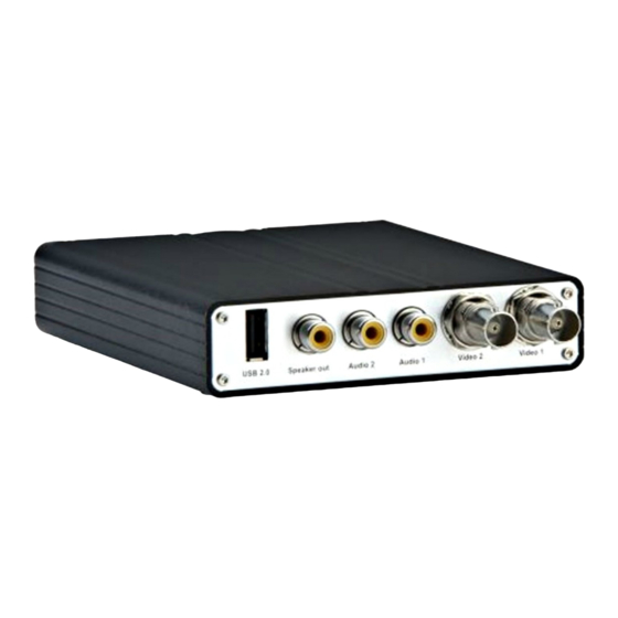
Introduction 1.7.1.3 GV-VS12 Figure 1-3 No. Name Function USB Port 1 USB port for installing the portable storage device. Speaker Output A plug for the speaker device. Audio Input 2 plugs for audio inputs. Video Input 2 plugs for video inputs.
Page 24
1.7.1.4 GV-VS2420 / 2400 Figure 1-4 No. Name Function Power LED This LED is on, indicating the power is supplied. This LED is on, indicating the GV-Video Server is ready for Ready LED connection. Disk Full/Fault This LED is on, indicating the hard drive is full or faulty. Reset It reboots the GV-Video Server and keeps all current configurations.
Page 25
Introduction 1.7.1.5 GV-VS2401 Figure 1-5 No. Name Function Power LED This LED is on, indicating the power is supplied. This LED is on, indicating the GV-Video Server is ready for Ready LED connection. Disk Full/Fault This LED is on, indicating the hard drive is full or faulty. Reset It reboots the GV-Video Server and keeps all current configurations.
Page 26
1.7.1.6 GV-VS2820 / 2800 Figure 1-6 No. Name Function Audio Out A plug for the speaker device. Audio In 4 plugs for max. 8 audio inputs. Video Input 8 plugs for video inputs. It reboots the GV-Video Server, and keeps all current Reset configurations.
Page 27
Introduction 1.7.1.7 GV-VS21600 Figure 1-7 No. Name Function Reset It reboots the GV-Video Server, and keeps all current configurations. It resets all configurations to their factory settings. See 6.4 Restoring to Default Button Factory Default Settings. Audio Out A plug for the speaker device. Audio In A DVI plug connected with16 RCA ports for audio inputs.
1.7.2 Rear View 1.7.2.1 GV-VS04H / 14 Figure 1-8 No. Name Function USB Port 2 USB ports for installing portable storage devices. The connectors for digital inputs, relay outputs, PTZ cameras, Terminal Block Wiegand device and GPS module control. See Chapter 9 Auxiliary Device Connectors.
Page 29
Introduction 1.7.2.2 GV-VS11 Figure 1-9 No. Name Function USB Port 1 USB port for installing portable storage device. A plug for inserting an Ethernet cable to build the network Ethernet Port connection. The connectors for digital input, digital output and PTZ camera Terminal Block control.
Page 30
1.7.2.4 GV-VS2420 / 2400 Figure 1-11 No. Name Function USB Port 2 USB ports for installing portable storage devices. The connectors for digital inputs, digital outputs, and PTZ cameras. Terminal Block See Chapter 9 Auxiliary Device Connectors. Gigabit Ethernet A plug for a 10/100/1000 Base-T Ethernet Port A plug to power the camera, by using the optional DC Power Out...
Page 31
Introduction 1.7.2.5 GV-VS2401 Figure 1-12 No. Name Function Gigabit Ethernet A plug for a 10/100/1000 Base-T Ethernet Port USB Port 2 USB ports for installing portable storage devices. The connectors for digital inputs, digital outputs, and PTZ cameras. Terminal Block See Chapter 9 Auxiliary Device Connectors.
Page 32
1.7.2.6 GV-VS2820 / 2800 / 21600 Figure 1-13 No. Name Function Gigabit Ethernet A plug for a 10/100/1000 Base-T Ethernet Port USB Port 2 USB ports for installing portable storage devices. The connectors for digital inputs, digital outputs and PTZ cameras. 3 Terminal Block See Chapter 9 Auxiliary Device Connectors.
2.1 Installing on a Network These instructions describe the basic connections to install the GV-Video Server on the network. Here we use GV-VS04H as an example for demonstration. Figure 2-1 1. Connect your camera’s video output to the BNC video input.
Page 34
Note: 1. GV-VS11 / 14 / 2420 / 2400 / 2401 / 2820 / 2800 / 21600 do not support PoE function. 2. For the users of other models, see the optional accessories in 1.6 Options. 3. GV-Video Server cannot work with microphones requiring power from the unit. Use the microphone that has external power supply.
GV-Video Server when connecting to the network. Follow the steps below to look up the IP address and access the Web interface. Install the GV-IP Device Utility program from GeoVision download page: http://www.geovision.com.tw/download/product/. Note: The PC installed with GV-IP Device Utility must be under the same LAN as the GV-Video Server you wish to configure.
2.3 Changing the IP Address To assign a static IP address or establish a connection to your ISP, log in the Web interface to access the network setting page. Note: If your router does not support DHCP, the default IP address will be 192.168.0.10. In this case, it is strongly suggested to modify the IP address to avoid IP address conflict with other GV-IP device on the same LAN.
Getting Started IMPORTANT: • PPPoE should only be enabled if you know which IP address the GV-Video Server will get from the ISP. Otherwise, you must use the Dynamic DNS service to obtain a domain name linked to the GV-Video Server’s changing IP address first. For details on Dynamic DNS Server settings, see 4.7.3 Advanced TCP/IP.
Chapter 3 Accessing the GV-Video Server Two types of users are allowed to log in the GV-Video Server: Administrator and Guest. The Administrator has unrestricted access to all system configurations, while the Guest has the access to live images and network status only. 3.1 Accessing Your Surveillance Images Once installed, your GV-Video Server is accessible on a network.
Page 39
Accessing the GV-Video Server Note: To enable the updating of images in Microsoft Internet Explorer, you must set your browser to allow ActiveX Controls and perform a one-time installation of GeoVision’s ActiveX component onto your computer.
▼ Network ► Status Figure 3-2 Main page of GV-VS04H in Guest Mode For GV-VS11 / 14 / 2420 / 2400 / 2401 / 2820 / 2800 / 21600 users, you can process each video stream in two different image settings. In the Administrator mode, both streams are available.
Accessing the GV-Video Server 3.2.1 The Live View Window In the left menu, click Live View and select the desired Camera to see live video. 2 3 4 5 6 7 Figure 3-3 No. Name Function Play Plays live video. Stop Stops playing video.
Page 42
Change Camera Sets the desired camera for display. Brings up these functions: Alarm Notify, Video and Audio Configuration, Remote Config, Show Camera Name and Show System Image Enhance. --- See 3.2.6 Alarm Notification, 3.2.7 Video Menu and Audio Configuration, 3.2.8 Remote Configuration, 3.2.9 Camera Name Display and 3.2.10 Image Enhancement respectively.
[GPS] For details, see 6.3 GPS Tracking. This function is not supported by GV-VS11 and GV-VS2420 / 2400 / 2401 / 2820 / 2800 / 21600. [Download] Allows you to install the OCX programs from the hard drive. This function is only supported by GV-VS04H / 11 / 12 / 14.
Page 44
[Internal Temperature] Displays the current chipset temperature inside the camera. This function is only available for GV-VS2420 / 2400 / 2401 / 2820 / 2800 / 21600.
Accessing the GV-Video Server 3.2.3 Snapshot of a Live Video To take a snapshot of live video, follow these steps: 1. Click the Snapshot button (No. 5, Figure 3-3). The Save As dialog box appears. 2. Specify Save in, type the File name and select JPEG or BMP as Save as Type. You may also choose whether to display the name and date stamps on the image.
Page 46
Picture-in-Picture View With the Picture in Picture (PIP) view, you can crop the video to get a close-up view and zoom in on the video. Navigation box Inset window Figure 3-6 1. Select PIP. An inset window appears. 2. Click the inset window. A navigation box appears. 3.
Page 47
Accessing the GV-Video Server Picture-and-Picture View With the Picture and Picture (PAP) view, you can create a split video effect with multiple close-up views on the image. A total of 7 close-up views can be defined. Figure 3-7 Select PAP. A row of three inset windows appears at the bottom. Draw a navigation box on the image, and this selected area is immediately reflected in one inset window.
3.2.6 Alarm Notification Upon input trigger and motion detection events, you can be alerted by a pop-up live video and view up to four captured images. Pop-up live video Captured images Figure 3-8 To configure this function, click the Show System Menu button (No. 11, Figure 3-3), and select Alarm Notify.
Accessing the GV-Video Server 3.2.7 Video and Audio Configuration You can enable the microphone and speaker for two-way audio communication and adjust the audio volume. To change audio configuration, click the Show System Menu button (No. 11, Figure 3-3) and select Video and Audio Configuration. Note: 1.
3.2.9 Camera Name Display To display the camera name on the image, click the Show System Menu button (No. 11, Figure 3-3) and select Show Camera Name. 3.2.10 Image Enhancement To enhance the image quality of live video, click the Show System Menu button (No. 11, Figure 3-3) and select Image Enhance.
Accessing the GV-Video Server 3.2.11 PTZ Control To open the PTZ control panel, click the PTZ Control button (No. 9, Figure 3-3) and select PTZ Control Panel. Note: Different PTZ devices have different functions, so the features included in the Option button may vary.
3.2.12 Visual PTZ In additional to the PTZ control panel, you can display a Visual PTZ control panel on the image. This feature is only available when the PTZ is predefined by the Administrator. For details, see 4.2.1 PTZ Settings. Figure 3-13 To access this feature, click the PTZ Control button (No.
Accessing the GV-Video Server 3.2.13 I/O Control The I/O Control window provides real-time graphic displays of camera, I/O status and alarm events. Additionally, you can force output to be triggered. Figure 3-14 To display the I/O control window, click the I/O Control button (No. 8, Figure 3-3). The Alarm List is displayed in three levels.
3.2.14 Visual Automation The Visual Automation allows you to change the current state of the electronic device by simply clicking on its image, e.g. turning the light ON. This feature is only available when the Visual Automation is predefined by the Administrator. For details, see 4.1.7 Visual Automation.
Administrator Mode Chapter 4 Administrator Mode The Administrator can access the system configuration of GV-Video S erver via the Internet. There are eight catego ries of the system configuration: Video and Motion, Digital I/O and PTZ, Events and Alerts, Monitoring, Recording Schedule, Remote ViewLog, Network, and Management.
Page 56
Note: For some models, you will see t he following two different user interfaces. Use them properly to help manage your camera settings. To access the live views or arrange the settings for individual cameras, select the desired stream and camera from the switch buttons at the top of the setting page. Figure 4-2 To manage specific input / output or camera setting functions, click the number buttons to make the selection or click ALL to configure a certain setting for all at once.
Page 57
Administrator Mode List of Menu Options Find the topic of interest by referring to the section number prefixed to each option. The available options vary amon g different vid eo server models. 4.1.1 Multic 4.1.2 Vid eo Settings 4.1.3 Motion Detection 4.1.4 Privacy Mask...
Page 58
The options or functions on the left menu of the Web interface (Figure 4-1) m ay vary depending on th e models. The table below provides an overview of their major differences in supported fu tions. Model GV-VS04H GV-VS11 GV-VS12 GV-VS14 GV-VS2420 / 2400 / (FW V1.03 or...
Multicast, Motion Detection, Privacy Mask, Tampering Alarm, Visual Automation and Video Channel Source Settings. 4.1.1 Multicast Note this function is only available for GV-VS04H (Firmware Version 1.03 or later), GV- VS11 / 12 (Firmware Version 1.05 or later) and GV-VS14.
3. To receive audio broadcasting, first ensure a speaker is properly in stalled on the local computer. Then click the Configure button, select General Setup, se lect Receive broadc ast audio, and ensure the broadcast IP address and port number are correctly configured.
Page 62
Automatically detects the type of video input ween NTSC or PAL. For GV-VS04H / 11 / 12 / 14, select to enable this function. r GV-VS2420 / 2400 / 2401 / 2820 / 2800 / 21600, this f unction is enabled by fault.
Page 63
Administrator Mode The image resolution varies from model to model. NTSC Models 704 x 480 704 x 576 GV-VS04H 704 x 480 de-interlace 704 x 576 de-interlace GV-VS11 352 x 240 352 x 288 12 / 14 176 x 176 x...
Page 64
For GV-VS04H / 11 / 12 / 14 / 2420 / 2400 / 2401, set the Maximal Bitrate to 1, 2, 4, 6, or 8 Mbit. For GV-VS2820 / 2800 / 21600, set the Maximal Bit Rate to 1, 2, 3, or 4 Mbit.
Page 65
4096 kbps, 3072 kbps, 2048 kbps, 1024 kbps, 512 kbps. 2800 / 21600 [GOP Structure and Length] Set the maximum number of seconds between every key frame. For GV-VS04H / 11 / 12 / 14, select Customized in the Connection Template section before setting the length of GOP structure .
Page 66
Watermark. the video has been tampered with. See 6.5 Ver [Apply All Settings] Apply the settings to all cameras: Applies the same settings to other cameras. Note this function is only supported by GV-VS04H / 11 / 12 / 14.
Administrator Mode 4.1.3 Motion Detection Motion detection is used to generate an alarm whenever moveme nt occurs in the video image. You can configure up to 8 areas with different sensitivity values for motion detection. Figure 4-6 1. The default sensitivity value for the whole area is 2 for GV-VS0 4H and GV-VS11 / 12 / 14, and the value is 9 for GV- VS2420 / 2400 / 2401 / 2820 / 2800 / 21600.
Page 68
Sunday or Only Sunday. C. Click Apply to save the above settings. Note this function is only supported by GV-VS04H / 11 / 12 / 14. Note: For GV-VS11 / 12 users, this function does not work whe n MJPEG codec is selected in the Video Signal Type field (Figure 4-1).
Administrator Mode 4.1.4 Privacy Mask The Privacy Mask can block out sensitive areas from view, covering the a reas with dark boxes in both live view and recorded clips. This feature is ideal for loca tions with displays, keyboard sequences (e.g. passwords), and for anywhere else you don’t want sensitive information visible.
4.1.5 Text Overlay Note this option is only available for GV-VS04H (Firmware Version 1.0 3 or later), GV-VS11 / 12 (Firmware Version 1.02 or later) and GV-VS14 / 2420 / 2400 / 2401 / 2820 / 2800 / 21600. The T ext Overlay function allows you to type any text in any place on the camera view.
Administrator Mode 4.1.6 Tampering Alarm Note this option is only available for GV-VS04H (Firmware Version 1.0 3 or later), GV-VS11 / 12 (Firmware Version 1.02 or later) and GV-VS14 / 2420 / 2400 / 2401 / 2820 / 2800 / 21600.
Page 72
When the camera is tampered with, the output device and system buz zer can be activated. To turn off the output device and system buzzer immediately, return to this setting page, and click Restart Detection. Note: The system buzzer is only supported by GV-VS04H (Firmware Version 1.03 or later).
Administrator Mode 4.1.7 Visual Automation Note this option is only available for GV-VS04H / 11 / 12 / 14 / 2400 / 242 This intuitive feature helps you automate any electronic device by trigger ing the connected output device. You can change the current state of the connected device by clicking on its image, e.g.
4.1.8 Video Channel Source Settings Note this option is only available for GV-VS04H (Firmware Version 1.03 or later). The function allows you to assign the video input to the desired video channel for display. Figure 4-14...
1. Digital Input / Output 2. RS-485 interface or coaxial connection for PTZ control 3. Wiegand interface for access control (only available on V-VS04H and GV-VS14) 4. GPS interface for vehicle tracking: UART: available on GV-VS04H and GV-VS14 RS-232: available on GV-VS12...
4.2.1 PTZ Settings You can connect up to 4 PTZ cameras to your GV-VS2420 / 2400 / 2401 video server, up to 8 PTZ cameras to your GV-VS2820 / 2800, and up to 16 PTZ cameras to your GV-VS2160 0 video server through RS-485 interface on the I/O terminal block. In addition, you can also connect your GV-VS2420 / 2400 / 2401 / 2800 / 21600 directly through coaxia l cables.
The number of input and output devices the GV-Video Server can connect to vary from model to model. The GV-VS04H / 14 / 2420 / 2400 / 2401 can connect up to 4 input and 4 output devices, GV-VS11 can connect 1 input and 1 output device, GV-VS12 can connect up to 2 input and 2 output devices, and GV-VS2820 / 2800 / 21600 can connect up to 8 input and output devices.
Page 78
Input Setting Figure 4-16 Normal State: Set up the input state to trigger actions by selecting Open Circuit (N/O) or Grounded Circuit (N/C). Latch Mode: Enable the mode to have a momentary output alarm Trigger Digital Outp ut Relay: Select the output(s) to be triggered once the input is activated.
Page 79
(Stop Record), disk write error (Rec Error) and hard disk full (HD Full). Note the video recording start / stop function is only supported by GV-VS04H / 11 / 12 / 14. Important: The input/output settings only function after you start I/O Monitor manually or by schedule.
Figure 4-19 GPS Function Note this function is only available for GV-VS04H, GV-VS12 and GV-VS14. The GV-Video Server supports the Global Position System (GPS) f or active vehicle tracking and location verification. You can track the vehicle location on Google maps and display the average spe ed of a vehicle in live view.
Page 81
IS connection, see 4.3.5 GV-GIS. Note this function is only availabl e for GV-VS04H (Firmware V1.03 or later), GV-VS12 (Firmware Version 1.04 or later) and GV-VS14. Sync GPS Time: Synchronizes the time of GV-Video Server with the GPS time once GV-Video Server receiv es GPS signals.
Page 82
Wiegand Function Note this function is only available for GV-VS04H and GV-VS14. The GV-Video Server can work in conjunction with the Wiegand-interfac e card reader to send video and cardholder data to the central monitoring stations Cente r V2 and Vital Sign Monitor, as well as GV-DVR / NVR.
Administrator Mode 4.2.4 Buzzer Note this function is only available for GV-VS04H (Firmware Version 1.03 or later). The system buzzer can be activated automatically under these condit ions: video lost, input device triggered, motion detected, disk full, disk write error and tampering alarm.
4.3 Events & Alerts For the events of motion detection or I/O trigger, the Administrator can set up the two trigger actions: 1. Send a captured snapshot by e-mail or FTP. 2. Notify Center Monitoring Station, Center V2, Vital Sign Monitor or GV-GIS, by video or text alerts.
Administrator Mode 4.3.1 E-mail After a trigger event, the GV-Video Server can send the e-mail to a remote user containing a captured snapshot. Figure 4-23 [Enable] Select to enable the e-mail function. Sever URL/IP Address: Type the SMTP Server’s URL address or IP address.
Page 86
2. The Motion Detection and Digital Input options (under the Alarm Settings section) are only available for GV-VS04H (Firmware Version 1.03 or later), GV-VS11 / VS12 (Firmware Version 1.04 or later) and GV-VS14 / 2420 / 240 0 / 2401 / 2820 / 2800 / 21600.
Administrator Mode 4.3.2 FTP You can also send the captured snapshot to a remote FTP server for alerts. Figure 4-24 [Upload to a FTP Server] Enable: Select to enable the FTP function. Server URL/IP Address: Type the URL address or IP address of the F TP Server.
Page 88
[Alarm Settings] Motion Detection: Once the motion is detected on the selected camera, a snapshot will be sent to the FTP Server as a notification. Continuous ly send images upon trigger events (motion): A sequence of snapshot images are uploaded to the FTP Server when motion is detected on the selected camera.
Administrator Mode 4.3.3 Center V2 Upon motion detection or I/O trigger events, the central monitoring station Center V2 can be notified by live videos and text alerts. Up to two Center V2 ser vers can be connected simultaneously. For live monitoring through Center V2, you must already have a subscriber account on each Center V2 server.
Page 90
To enable the Center V2 connection: 1. Activate Link: Enable the monitoring through Center V2. 2. Host Name or IP Address: Type the host name or IP address of Center V2. 3. Port Number: Match the port to Port 2 on Cen ter V2.
Administrator Mode 4.3.4 Vital Sign Monitor Upon motion detection or I/O triggered events, the central monitor ing station Vital Sign Monitor can be notified by text alerts. Up to two Vital Sign Monitor s ervers can be connected simultaneously. For live monitoring through Vital Sign Monitor, you must already have a subscriber account on each Vital Sign Monitor server.
Page 92
7. To establish the connection to the second Vital Sign Monitor server, click the Connection 2 tab and repeat the above steps for setup. You can also find these options on this Vital Sign Monitor setting pa Cease motion detection messages from: Stops notifying Vital Sig n Monitor of motion detection from t he selected camera.
Administrator Mode 4.3.5 GV-GIS Note the GV-GIS with two connections is only available on GV-VS04H (Firmware Version 1.03 or later), GV-VS12 (Firmware Version 1.02 or later) and GV-VS14. Through the Internet connection, the GV-Video Server with enabled-GPS function can send GPS data and live video to the GV-GIS geographic information system for the services of vehicle tracking, location verification and live monitoring.
Page 94
To enable the GV-GIS connection: 1. Activate Link: Enable the monitoring through GV-GIS. 2. Host Name or IP Address: Type the host name or IP address of GV-GIS. 3. Port Number: Match the communication po rt on GV-GIS. Or keep the default value 3356.
Administrator Mode 4.3.6 Backup Center Note the function is only available for GV-VS04H (Firmware Version 1. 03 or later), GV- VS11 / 12 (Firmware Version 1.02 or later) and GV-VS14 / 2420 / 2400 / 2401 / 2820 / 2800 / 21600.
Page 96
Note: The Backup Video, Compact Video and Resend all files functions are only available for GV-VS04H (Firmware Version 1.03 or later), GV-VS11 / 12 (Firmware Version 1.02 or later) and GV-VS14 / 2420 / 2400 / 2401 / 2820 / 2800 / 21600.
Administrator Mode 4.3.7 Video Gateway/Recording Server Note the function is only available on GV-VS04H (Firmware Version 1.03 or later), GV-VS11 / 12 (Firmware Version 1.02 or later) and GV-VS14 / 2420 / 2400 / 2401 / 2820 / 2800 / 21600.
Page 98
The GV-Video Server can connect up to two GV-Video Gateway / GV-R ecording Server. To send the video images to the GV-Video Gateway or GV-Recording Server, follow the steps below. 1. Activate Link: Enable the connection to GV-Video Gateway / GV-Re cording Server.
Administrator Mode 4.3.8 ViewLog Server The ViewLog Server is designed for remote playback function. This serve r allows you to remotely acces s the recorded files saved at the GV-Video Server and play back video with the player ViewLog. Select Enable to activate the built-in server. Keep the default port 5552 or modify it if necessary.
4.3.9 3GPP/RTSP/ONVIF The 3GPP / RTSP / ONVIF Server enable video and audio streaming to your 3G-enabled mobile phone or third-party software. Figure 4-31 TSP / 3GPP Server] Activate Link: Ena ble the 3GPP / RTSP / ONVIF service. ...
Page 101
Administrator Mode [ONVIF] To enable these options, you must first select the Activate Link option ab ove. Enable Authentication: The ID and password of the cam era are required to access the camera when accessing by a third-party software through ON VIF.
4.4 Monitoring You can start recording manually, by schedule or by input trigger. Figure 4-32 [Manual] Manually activates motion detection and input monitoring. Select one of the following options and click the Start button. Select all: Manually start recording and input monitoring as well. ...
Page 103
Manual or Schedule options. [Stop monitor ing by Input X] This function is only supported by GV-VS04H / 11 / 12 / 14. Stop monitoring by the assigned input. When the assigned input is triggere d, the system will stop monitoring.
4.5 Recording Schedule The schedule is provided to activate recording and I/O monitoring on a specific time each day. 4.5.1 Recording Schedule Settings You can set up different monitoring schedules for each camera. Figure 4-33 Span 1- Span 3: S et a different recording mode for each time frame in a day.
TCP/IP network. For the first-time user, you need to install the Remote ViewLog program from http://www.geovision.com.tw/download/product/ . For remote access to the GV-Video Server, the ViewLog Server built in the unit must be enabled. See 4.3.8 ViewLog Server.
4.7 Network The Network section includes some basic but important network configurations that enable the GV- Video Server to be connected to a TCP/IP network. 4.7.1 LAN According to your network environment, select among Static IP, DHCP and PPPoE. Figure 4-35 [Optional Network type] According to the network environment, select Wired or Wireless.
Page 107
Administrator Mode [LAN Configuration] Dynamic IP address: The network environment has a DHCP server . By default, the GV-Video Server will be automatically assigned a dynam ic IP address by the DHCP server. To check the current IP address, click the Test DHCP button. ...
4.7.2 Wireless-Client Mode To use the wireless function, a wireless LAN USB adaptor is required. For supported wireless LAN adaptors, see Appendix B. Figure 4-36 Network type: Select the network mode Ad Hoc or Infrastructure Infrastructure: Via the Access Point to connect to the Internet. This mode further gives wireless access to the Internet or data sharing under a p reviously wired environment.
Page 109
Administrator Mode WPAPSK-TKIP and WPA2PSK-TKIP: Type WPA-PSK (Pre-Shared Key) for data encryption. WPAPSK- AES and WPA2PSK-AES: Type WPA-PSK (Pre-Shared Key) for data encryption. Note: 1. Your encryption settings must match those used by the Access Poin ts or wireless stations in which you are connecting to.
4.7.3 Advanced TCP/IP This section introduces the advanced TCP/IP settings, including DDNS Server, HTTP port, HTTPS port, streaming port and UPnP. Figure 4-37...
Page 111
Apply. The Web interface will be restarted and you will need to log in again. Note this function is only available for GV-VS04H (Firmware V1.03 or later), GV-VS11 / 12 (Firmware Version 1.04 or later) and GV-VS14 / 2420 / 2400 / 2401 / 2820 / 2800 / 21600.
Page 112
The function is currently supported with Windows Media Player for recording playback. Note: The DLNA function is only supported by GV-VS04H / 11 / 12 / 14. The DLNA function is only supported with Windows Media Player version 1.1 or later.
Page 113
The default value is 0, meaning QoS is disabled. Note this function is only available for GV-VS04H (Firmware Version 1.05 or later), GV- VS11 / 12 (Firmware Version 1.05 or later) and GV-VS14 / 2420 / 2400 / 2401 / 2820 /...
4.7.4 UMTS UMTS stands for Universal Mobile Telephone System. UMTS is a third -generation (3G) broadband, packet-based transmission of text, digitized voice, video, and multimedia at data rates up to 2 megabits per second. UMTS offers a consistent set of services to mobile computer and phone users, no matter where they are located in the world.
Page 115
Administrator Mode PIN number: Type the PIN number that is provided by your ne twork operator. Access Poi nt Name (APN): Type Access Point Name that is provided by your network operator. Username: Type a valid username to enable the UMTS service from your network operat ...
4.7.5 Multicast Note this function is only available for GV-VS04H (Firmware Version 1.03 or later), GV- VS11 / 12 (Firmware Version 1.05 or later) and GV-VS14. The multicast provides a mechanism for sending a single video and audio stream to a group of hosts.
Administrator Mode Enable Encryption: Enable this option and type the Encryption Key to secure multicast streams. The hosts in the multicast group will need to enter the Key to access the video and audio streams. Enable Audio callback: Enable this option to receive aud io broadcasting from hosts in the multicast group.
SNMP network management software. Note this function is only available for GV-VS04H (Firmware Version 1.05 or later), GV-VS11 / 12 (Firmware Version 1.05 or later) and GV-VS14 / 2420 / 2400 / 2401 / 2820 / 2800 / 21600.
Administrator Mode 4.8 Management The Management section includes the settings of data and time, USB mass storage device and user account. Also, you can view the firmware version and execute certain system operations such as language sett ing. 4.8.1 Date and Time Settings The date and time settings are used for date and time stamps on the image.
Page 120
[Date & Time on Video server] Displays the current date and time on the GV-Video Server. [Time Zone] Sets the time zone for local settings. Select Enable Dayligh t Saving Time to automatically adjust the GV-Video Server for daylight saving time. Type the Start Time and End Time to enable the daylight saving function.
Administrator Mode 4.8.2 GPS Maps Settings Note this function is only available for GV-VS04H / 12 / 14. The GV-Video Server supports the Global Position System (GPS) for act ive vehicle tracking and location verification. The vehicle location will be tracked by Google Maps.
The GV-Video Server does not support USB2.0 to SATA / IDE c able for external storage connection. GV-VS04H / 11 / 12 / 14 support up to 2 TB hard disk, GV-VS2420 / 2400 supports up to 4 TB hard disk, an d GV-VS2401 / 2820 / 2800 / 21600 supports up to 6 TB hard disk.
Page 123
Administrator Mode [Storage Settings] If the Enable recycling option is checked, when the space of the USB mass storage device is lower than the specified sp ace, the system will either write the data to another device or overwrite the oldest recorded files. If the Enable recycling option is not checked, the system will stop rec ording when the specified space is reached.
Page 124
Note: 1. If Enable Recycle is selected, the available space of the USB mass storage device must be higher than the space you specified at the Stop recording or recycle disk when free space of disk is smaller than x option. Otherwise no v ideo will be recod 2.
Administrator Mode 4.8.4 User Account You can change the login name and password of Administrator, Guest and FTP Server ser. The default Administrator login name and pa ssword are admin. The default Guest login name and password are guest. ...
4.8.5 Log Information The Startup time log section contains every start time of the GV-Video Server. The start time is recorded on the local storage device , so the information is only available when a storage device is connected to the GV-Video Server. The Debug Messages section contains dump data that is used by service personnel for analyzing problems.
Administrator Mode 4.8.6 System Log Note the function is only available on GV-VS04H (Firmware Version 1.03 or later), GV- VS11 / 12 (Firmware Version 1.02 or later) and GV-VS14. The System Log records the events in four types of logs: System Even...
4.8.7 Tools This section allows you to execute certain system operations and view the firmware version. Figure 4-49...
Page 129
Reboot Time: Use the drop-down lists to specify the time for aut omatic reboot. e this function is only available for GV-VS04H (Firmware Version 1.03 or later), GV- VS11 / 12 (Firmware V1.04 or later) and GV-VS14 / 2420 / 2400 / 2401 / 2820 / 2800 / 21600.
4.8.8 Language You can select the language for the Web interface. Figure 4-50 Use the Language drop-down list to select a language for the Web interface. By default, the language on the Web interface will be the same with the one used for the operating system.
Recording and Playback Chapter 5 Recording and Playback The GV-Video Server can record down video/audio directly to the attached USB mass storage device. And you can play back the recorded files on the GV-DVR / NVR / VMS or over the TCP/IP network. 5.1 Recording To enable the recording function: 1.
Windows to recognize Linux files, you need to install the ExtFS program from GeoVision Website. 1. Visit GeoVision download page at http://www.geovision.com.tw/download/product/, type the model name of your GV-Video Server on the search bar. 2. Select Supplemental Utilities from the drop-down list, and click the Download icon of ExtFS - ExtFS File System Driver.
With the Remote ViewLog function, you can play back the files recorded at the GV-Video Server over TCP/IP network. Installing Remote ViewLog For first-time users, install Remote ViewLog from GeoVision Website. Once installed, you can access this option from GV-Video Server’s Web interface. To install Remote ViewLog, follow the steps below: 1.
Page 134
Playing Back from Remote ViewLog You must enable ViewLog Server on the GV-Video Server’s Web interface to allow remote access. See 4.3.8 ViewLog Server. Run the Remote ViewLog program and select Remote ViewLog Service. A dialog box appears. Type the GV-Video Server’s IP address, login ID and password. Keep the default port 5552 or modify it if necessary.
Recording and Playback 5.2.3 Playback of GPS Tracks On GV-DVR / NVR, you can retrieve the GPS tracks from GV-Video Server for playback. You can also attach the USB mass storage device with the GPS data to GV-DVR / NVR for playback.
Page 136
Figure 5-5 Note: 1. The GPS function is only available for GV-VS04H / 12 / 14. 2. For the versions compatible with the playback function by connecting GV-Video Server to GV-DVR / NVR, see CH7 DVR / NVR / VMS for details.
This chapter introduces more advanced applications. 6.1 Upgrading System Firmware GeoVision will periodically release the updated firmware on the website. The new firmware can be simply loaded into the GV-Video Server by using the Web interface or installing the GV-IP Device Utility from http://www.geovision.com.tw/download/product/.
6.1.1 Using the Web Interface 1. In the Live View window, click the Show System Menu button (No. 11, Figure 3-3), select Remote Config. This dialog box appears. Figure 6-1 2. Click the Browse button to locate the firmware file (.img) saved at your local computer. 3.
The IP Device Utility provides a direct way to upgrade the firmware to multiple GV-Video Servers. 1. Install the GV-IP Device Utility program from GeoVision download page: http://www.geovision.com.tw/download/product/. 2. Double-click the GV IP Device Utility icon created on your desktop. This dialog box appears.
5. Click the Firmware Upgrade tab. This dialog box appears. Figure 6-4 6. Click the Browse button to locate the firmware file (.img) saved at your local computer. 7. If you like to upgrade all the GV-Video Servers in the list, check Upgrade all devices. 8.
Advanced Applications 3. Click the Export Settings button. This dialog box appears. Figure 6-5 4. Click the Browse button to assign a file path. 5. Type Password and click Export Settings to save the backup file. 6.2.2 Restoring the Settings 1.
6.3 GPS Tracking Note this function is only available for GV-VS04H / 12 / 14. The GV-Video Server supports the Global Position System (GPS) for active vehicle tracking and location verification. The vehicle location will be tracked by Google Maps.
Advanced Applications 5. To track the GV-Video Server on Google Maps, click Open. A warning message appears. Figure 6-8 6. Right-click the warning message and select Allow Blocked Content. The map will be displayed. The icon indicates the location of your GV-Video Server. At the upper right corner you have options for viewing different map formats, such as Satellite and Hybrid.
To restore to default settings, use the Reset and Load Default buttons on the front panel. For the location of the two buttons see 1.7 Physical Description. GV-VS04H / 14 1. Press and then release the Reset button immediately. 2. Press and hold the Load Default button until all 3 LEDs (Power, Ready and Disk Full/Fault) are on.
Advanced Applications 6.5 Verifying Watermark Note this function is only available for GV-VS04H (Firmware Version V1.03 or later), GV- VS11 / 12 (Firmware Version V1.02 or later) and GV-VS14 / 2420 / 2400 / 2401 / 2820 / 2800 / 21600.
6.5.3 The Watermark Proof Window Figure 6-10 The controls in the window: No. Name Description Open File Opens the recorded file. First Frame Goes to the first frame of the file. Play Plays the file. Previous Frame Goes to the previous frame of the file. Next Frame Goes to the next frame of the file.
Figure 7-1 GV-DVR / NVR The compatible versions of GV-DVR / NVR / VMS for each model: Compatible version of Compatible version of Model GV-DVR / NVR GV-VMS GV-VS04H 8.4.3 or later GV-VS11 8.5.3 or later 14.10 GV-VS12 8.3.2 or later GV-VS14 8.5.5 or later...
Page 148
The maximum number of streams that a GV-Video Server allows is 8 (GV-VS04H) / 16 (GV-VS14, GV-VS2420 / 2400 / 2401 / 2820 / 2800 / 21600) / 4 (GV-VS11 / 12). For GV- VS04H / 12, when a channel is connected to GV-DVR / NVR / VMS, IE browser, or any other application, it takes up 1 stream.
DVR / NVR / VMS 7.1 Setting Up GV-Video Server on GV-DVR / NVR To set up the cameras from the GV-Video Server on the GV-DVR / NVR, follow these steps: On the main screen, click the Configure button, select System Configure, select Camera Install and click IP Camera Install.
Page 150
Type the IP address, username and password of the GV-Video Server. Modify the default HTTP port if necessary. Select GeoVision from the Brand drop-down list and select the GV-Video Server model from the Device drop-down list. The following dialog box appears.
Page 151
DVR / NVR / VMS The GV-DVR / NVR will automatically query for the GV-Video Server, and the status will be indicated as “Standby”. Take GV-VS11 for example, if it is in a single stream, you can see one resolution and codec for Preview and Record in Code Type field.
7.1.1 Customizing GV-Video Server Settings After the GV-Video Server is connected and assigned with a display position, you can configure the GV-Video Server’s settings such as frame rate or resolution. Right-click the desired GV-Video Server to see the following list of options: Figure 7-7 ...
Page 153
MJPEG, MPEG4 or H.264 codec. GIS Setting: Note this function is only available for GV-VS04H / 12 / 14. Records the video with the GPS data. To record the GPS data, remember to also enable the GIS function of the GV-DVR / NVR (Configure button < Accessories < Enable Local GIS).
7.2 Setting Up GV-Video Server on GV-VMS To set up the cameras from the GV-Video Server on the GV-VMS, follow these steps: Note: The following instructions are based on GV-VMS V14.10 software and user interfaces. To access the IP Device Setup page, click Home , select Toolbar , click Configure...
Page 155
Type the IP address, username and password of the GV-Video Server. Modify the default HTTP port 80 if necessary. Select GeoVision and model name from the Brand drop-down list and select the GV-Video Server model from the Device drop-down lists.
Page 156
Take GV-VS11 for example, if it is in a single stream, you can see one resolution and codec for Preview and Record in Code Type field. Take GV-VS14 for example, if you want to enable dual streams, click the Dual Stream button to set up the H.264 codec and 704 x 480 resolution for recording and the MPEG4/MJEPG codec and 352 x 240 for live viewing.
DVR / NVR / VMS 7.3 Receiving Cardholder Data from Video Server This function is only available for GV-VS04H / 14. Over the network, GV-DVR / NVR can receive cardholder data from the Wiegand-interface card reader. This transmission is made possible through GV-Video Server.
Page 158
Click Add to add the Wiegand card reader to the system. Note the cardholder data will not be overlaid on the mapped camera. To view cardholder data, click the ViewLog button, select System Log to display the Live Log Browser and click the Device tab. Figure 7-15 For the related settings on the GV-Video Server, see Wiegand Function in 4.2.3 GPS/Wiegand.
You can use the Multi View to monitor and manage the cameras and I/O devices connected to the GV-Video Server. This function is only available for GV-VS04H / 11 / 12 / Note: Multi View is not supported by GV-VMS.
Select GV-Video Server from the Device drop-down list. Type the host name, IP address, user name and password of the GV-Video Server. Modify the default VSS port 10000 if necessary. Figure 7-16 6. Click Save to establish connection. For details on the Multi View functions, see “Multi View Viewer”, Chapter 8, GV-DVR User’s Manual.
Page 161
DVR / NVR / VMS 3. Double-click the New Map file, and click the Load Map button on the toolbar to import a graphic file. 4. To create a host, click the Add Host button on the toolbar and select Add Video Server.
Page 162
3. Select Emap. The valid user name and password are required for login. For the first- time user, you will be directed to the Download page. Install the E-Map program before you can run it. 4. On the Remote E-Map window, click the Login button and select the GV-Video Server host to access its videos and I/O devices.
CMS Configurations Chapter 8 CMS Configurations This section introduces the related settings to enable connecting to the GV-Video Server in the central monitoring stations Center V2, Vital Sign Monitor and Dispatch Server. 8.1 Center V2 The Center V2 can monitor and manage the cameras and I/O devices connected to the GV-Video Server.
Page 164
To define how to display the received video on motion detection and input trigger from the GV-Video Server, click the Preference Setting button and select System Configure. This dialog box appears. Figure 8-3 Manual close channel: Closes the triggered camera view manually. ...
CMS Configurations 8.2 Vital Sign Monitor The Vital Sign Monitor is designed to monitor and manage the cameras and I/O devices connected to the GV-Video Server under low bandwidth network. TCP/ IP GV-Video Server Text Data Vital Sign Monitor GV-Video Server Figure 8-4 ...
8.3 Dispatch Server The Dispatch Server minimizes overloading of Center V2 Servers by re-distributing GV- Video Server subscribers to the least busy Center V2 server. TCP/ IP GV-Video Server Center V2 Video Data Text Data Dispatch Server GV-Video Server Center V2 Figure 8-6 ...
Center V2 and Vital Sign Monitor, PTZ control and a variety of other functions. Figure 9-2 9.1.1 Pin Assignment The table below lists the pin assignment for the terminal block. GV-VS04H / 14 Function Function Relay Output 1 DC 5V Out for GV-Relay Module, or GPS Module...
Page 169
Auxiliary Device Connectors GV-VS2420 / 2400 / 2401 Function Function Digital Output 1 DC 5V Out for GV-Relay Module Digital Input 1 Ground Digital Output 2 RS 485+ Digital Input 2 Digital Output 3 RS 485- Digital Input 3 Digital Output 4 Ground Digital Input 4 DC 12V Out...
9.1.2 Relay Output The relay outputs on the terminal block only drives a maximum load of 5 volts. Working in conjunction with the GV-Relay V2 module, it is capable of driving heavier loads. Refer to the figure and table below to connect the GV-Relay V2 module to the GV-Video Server. Note: The GV-Relay module is an optional product.
Auxiliary Device Connectors 9.2 GV-VS11 The terminal block on the rear panel of GV-VS11 provides one digital input and output, an RS-485 interface and auxiliary power. RS-485 + 5V DI DO G Figure 9-4 Function RS-485- RS-485- RS-485+ RS-485+ DC 5V Out Digital Input Digital Output Ground...
9.3 GV-VS12 Owing to the model size, GV-VS12 provides I/O Cable with RJ-45 Connector for extensible connection to other I/O devices and PTZ cameras. A RJ-45 connector and a bundle of shielded wires are on each end of the cable. Strip the desired wires first, and connect the auxiliary devices with the right wires according to the following pin assignment in section 9.2.1.
Auxiliary Device Connectors 9.3.2 RS-232 Terminal Block The RS-232 terminal block on GV-VS12 is mainly used for connecting to a GPS module. RS232 Figure 9-6 Function GPS RX (Receive) GPS TX (Transmit) Ground DC 5V Out Note: To ensure the connection to the GV-VS12, the GPS RX must be connected to the TX pin, and the GPS TX must be connected to the RX pin.
Chapter 10 Mobile Phone Connection With mobile phones capable of GPRS, 3G and Wi-Fi, you can receive live videos from your GV-Video Server using GV-Eye V2.0 or later. To download the latest GV-Eye or see the full installation guide, visit http://www.geovision.com.tw/products.php?c2=147.
2. Enable Allow previously unused ActiveX controls to run without prompt. 3. Disable Only allow approved domains to use ActiveX without prompt. B. Supported Wireless LAN USB Adaptor GV-VS04H / 12 / 14 / 2420 / 2400 / 2401 / 2820 / 2800 / 21600 Vendor Model...
Appendix E. Supported PTZ Cameras The following table shows a list of supported PTZ cameras. PTZ Model and Protocol AcutVista (SSD-7971D) Ademco (Jupiter) Bosch (G3) Bosch (TC700 / 8560) Canon (VCC4 / VCC5i) CBC GANZ (ZC-S120 Series) Chiper (CPT-V9KRV) COP (15-CD53W) - Pelco D COP (15-CD55TW) - Pelco D COP (15-CD55W) - Pelco D COP (CD55X) - Pelco D...
Page 178
Lilin (PIH-7625) – MLP1 Lilin (PIH-820) – MLP1 MESSOA (SDS600 Series) MESSOA (D-700 Series) Minking Dome Mintron (54G2AHN / P) NanWang (NVD 2300PNT) NanWang V4.1 (NVD 2300PNT) Panasonic (WV-CS850) Panasonic (WV-CW960) Pelco Dome Pelco (Spectra III) Pelco Spetra Mini Dome (SD4-WO) Pishion (22X) PTZ in I/O RX214D...
Appendix F. The CGI Command Note this function is only supported by GV-VS04H (Firmware Version 1.03 or later), GV- VS11 / 12 (Firmware Version 1.04 or later) and GV-VS14 / 2420 / 2400 / 2401 / 2820 / 2800 / 21600.
Need help?
Do you have a question about the GV-VS04H and is the answer not in the manual?
Questions and answers