GeoVision GV-VS04H User Manual
Gv-video server
Hide thumbs
Also See for GV-VS04H:
- User manual (179 pages) ,
- Quick start manual (13 pages) ,
- How-to manual (15 pages)

Subscribe to Our Youtube Channel
Related Manuals for GeoVision GV-VS04H


Summary of Contents for GeoVision GV-VS04H
- Page 1 GV-Video Server User's Manual Before attempting to connect or operate this product, please read these instructions carefully and save this manual for future use. VS04HV108.VS12V107.VS11V103.VS14V101-A...
- Page 2 GeoVision. Every effort has been made to ensure that the information in this manual is accurate. GeoVision, Inc. makes no expressed or implied warranty of any kind and assumes no responsibility for errors or omissions. No liability is assumed for incidental or consequential damages arising from the use of the information or products contained herein.
- Page 3 The GV-Video Server has a series of models designed to meet different needs. Each model has its own firmware that can only be used on the specific model. This Manual is designed for the following models and firmware version: Model Firmware Version GV-VS04H 1.08 GV-VS11 1.03 GV-VS12 1.07...
-
Page 4: Table Of Contents
Contents Chapter 1 Introduction ............1 Models........................1 1.2 Packing List ......................2 1.2.1 GV-VS04H / GV-VS14 ................2 1.2.2 GV-VS11 ....................2 1.2.3 GV-VS12 ....................3 1.3 System Requirement ..................... 4 1.4 PoE Support ......................4 1.5 GPS Support......................4 1.6 Options ........................ - Page 5 3.2.12 Visual PTZ ....................27 3.2.13 I/O Control ....................28 3.2.14 Visual Automation...................29 3.2.15 Network Status ..................29 Chapter 4 Administrator Mode ...........30 4.1 Video and Motion....................33 4.1.1 Multicast ....................33 4.1.2 Video Settings ..................34 4.1.3 Motion Detection..................40 4.1.4 Privacy Mask ....................41 4.1.5 Text Overlay .....................42 4.1.6 Tampering Alarm ..................43 4.1.7 Visual Automation..................45 4.1.8 Video Channel Source Settings ..............46...
- Page 6 4.7.3 Advanced TCP/IP ..................79 4.7.4 UMTS .......................83 4.7.5 Multicast ....................85 4.7.6 IP Filter .....................86 4.7.7 SNMP Setting ...................87 4.8 Management......................88 4.8.1 Date and Time Settings ................88 4.8.2 GPS Maps Settings ..................90 4.8.3 Storage Settings ..................91 4.8.4 User Account ....................94 4.8.5 Log Information..................95 4.8.6 System Log....................96 4.8.7 Tools......................97 4.8.8 Languages....................99...
- Page 7 Chapter 8 CMS Configurations.........132 8.1 Center V2 ......................132 8.2 VSM........................134 8.3 Dispatch Server ....................135 Chapter 9 Auxiliary Device Connectors ......136 9.1 GV-VS04H and GV-VS14 ...................136 9.1.1 Pin Assignment..................136 9.1.2 Relay Output...................137 9.2 GV-VS11 ......................138 9.3 GV-VS12 ......................139 9.3.1 Pin Assignment..................139 9.3.2 RS-232 Terminal Block ................140...
- Page 8 10.3.1 Installing GV-SSView V3 ..............155 10.3.2 Activating the GV-SSView V3 Function..........155 10.3.3 Connecting to GV-Video Server ............155 10.3.4 Quick Connection .................156 10.3.5 Playing Back the Recordings from GV-Video Server......157 10.3.6 Other Functions ..................157 10.4 3G Mobile Phone ....................158 10.4.1 Activating the 3G Mobile Phone Function ..........158 10.4.2 Connecting to the GV-Video Server ............158 10.4.3 Playing Back the Recordings from GV-Video Server......160 10.5 Android Smartphone ..................162...
-
Page 9: Chapter 1 Introduction
Chapter 1 Introduction The GV-Video Server, including the models GV-VS04H, GV-VS11, GV-VS12 and GV- VS14, allows the conversion of any analog camera into a fully functional IP camera. It streams the real-time digital video over the Internet in the same way that current IP cameras do. -
Page 10: Packing List
1.2 Packing List 1.2.1 GV-VS04H / GV-VS14 1. AC Power Cord x 1 2. DC Male-to-Male Cable (for powering on the camera through GV-Video Server) x 1 3. Power Adaptor x 1 4. Wall Hook x 1 5. Conical Anchor x 4 6. -
Page 11: Gv-Vs12
Introduction 1.2.3 GV-VS12 1. AC Power Cord x 1 2. Power Adaptor x 1 3. I/O Cable with RJ-45 Connector x 1 4. Wall Hook x 1 5. Conical Anchor x 4 6. Screw x 4 7. Sticker (for positioning conical anchors) x 1 Figure 1-3 8. -
Page 12: System Requirement
Attached with the GV-GPS Receiver, the GV-Video Server allows you to perform vehicle tracking on Google Maps. The models supporting GPS function include: • GV-VS04H, GV-VS12 and GV-VS14. Different models of the GV-Video Server support different interfaces: • UART: GV-VS04H and GV-VS14 •... -
Page 13: Options
The GV-Video Server can work with the Wiegand-interface card reader to send cardholder data to the central monitoring stations Center V2 and VSM, as well as GV- System. The following devices are only supported by GV-VS04H and GV-VS14. GV-Reader includes transmit-receive antenna and GV-Reader electronics. -
Page 14: Physical Description
1.7 Physical Description This section identifies the various components of the GV-Video Server. 1.7.1 Front View 1.7.1.1 GV-VS04H / GV-VS14 Figure 1-4... - Page 15 Introduction No. Name Function Video Input 4 plugs for video inputs. Speaker Output A plug for the speaker device. Audio Input Each plug is for 2 audio inputs. It reboots the GV-Video Server, and keeps all current Reset configurations. It resets all configurations to their factory settings. See 6.4 Default Button Restoring to Factory Default Settings.
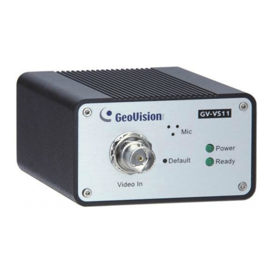
- Page 16 1.7.1.3 GV-VS11 Figure 1-5 No. Name Function Video Input 1 plug for video input. It resets all configurations to their factory settings. See 6.4 Default Button Restoring to Factory Default Settings. Audio Input 1 plug for audio input. This LED is on, indicating the GV-Video Server is ready for Ready LED connection.
-
Page 17: Rear View
Introduction 1.7.2 Rear View 1.7.2.2 GV-VS04H / GV-VS14 Figure 1-7 No. Name Function USB Port 2 USB ports for installing portable storage devices. The connectors for digital input, relay output, PTZ camera, Terminal Block Wiegand device and GPS module control. See Chapter 9 Auxiliary Device Connectors. - Page 18 1.7.2.3 GV-VS11 Figure 1-8 No. Name Function USB Port 1 USB port for installing portable storage device. A plug for inserting an Ethernet cable to build the network Ethernet Port connection. The connectors for digital input, digital output and PTZ camera Terminal Block control.
-
Page 19: Chapter 2 Getting Started
2.1 Installing on a Network These instructions describe the basic connections to install the GV-Video Server on the network. Here we use GV-VS04H as the example to demonstrate the steps. Figure 2-1 1. Connect your camera’s video output to the BNC video input. - Page 20 1. The GV-VS11 / GV-VS14 does not support PoE function. 2. The DC Male-to-Male Cable and 3.5 mm Stereo to RCA Cable are only supplied for GV-VS04H and GV-VS14. 3. The GV-Video Server cannot work with the microphone requiring power from the unit.
-
Page 21: Checking The Ip Address
Getting Started 2.2 Checking the IP Address By default, an unused IP address is automatically assigned by the DHCP server to the GV-Video Server when connecting to the network. Follow the steps below to look up the IP address and access the Web interface. Install the GV-IP Device Utility program included on the Software CD/DVD. -
Page 22: Changing The Ip Address
2.3 Changing the IP Address To assign a static IP address or establish a connection to your ISP, log in the Web interface to access the network setting page. Note: If your router does not support DHCP, the default IP address will be 192.168.0.10. In this case, it is strongly suggested to modify the IP address to avoid the IP address conflict with other GV-IP device on the same LAN. -
Page 23: Configuring The Basic
Getting Started IMPORTANT: • PPPoE should only be enabled if you know which IP address the GV-Video Server will get from the ISP. Otherwise, you must use the Dynamic DNS service to obtain a domain name linked to the GV-Video Server’s changing IP address first. -
Page 24: Chapter 3 Accessing The Gv-Video Server
4. A video image, similar to the example in Figure 3-2, is now displayed in your browser. Note: To enable the updating of images in Microsoft Internet Explorer, you must set your browser to allow ActiveX Controls and perform a one-time installation of GeoVision’s ActiveX component onto your computer. -
Page 25: Functions Featured On The Main Page
▼ Network ► Status Figure 3-2 Main page of GV-VS04H in Guest Mode For GV-VS11 and GV-VS14 users, you can process one video stream in two different image settings. In the Administrator mode, both streams are available. Click Streaming 1 or Streaming 2 in the left menu to access the live view. -
Page 26: The Live View Window
3.2.1 The Live View Window In the left menu, click Live View, and then select the desired Camera to see live video. . 2 3 4 5 6 7 Figure 3-3 No. Name Function Play Plays live video. Stop Stops playing video. Microphone Talks to the surveillance area from the local computer. -
Page 27: The Control Panel Of The Live View Window
Accessing the GV-Video Server 3.2.2 The Control Panel of the Live View Window To open the control panel of the Live View window, click the arrow button on top of the viewer. You can access the following functions by using the right and left arrow buttons on the control panel. -
Page 28: Snapshot Of A Live Video
3.2.3 Snapshot of a Live Video To take a snapshot of live video, follow these steps: 1. Click the Snapshot button (No. 5, Figure 3-3). The Save As dialog box appears. 2. Specify Save in, type the File name, and select JPEG or BMP as Save as Type. You may also choose whether to display the name and date stamps on the image. - Page 29 Accessing the GV-Video Server Picture-in-Picture View With the Picture in Picture (PIP) view, you can crop the video to get a close-up view or zoom in on the video. Navigation box Inset window Figure 3-5 1. Select PIP. An inset window appears. 2.
- Page 30 Picture-and-Picture View With the Picture and Picture (PAP) view, you can create a split video effect with multiple close-up views on the image. A total of 7 close-up views can be defined. Figure 3-6 Select PAP. A row of three inset windows appears at the bottom. Draw a navigation box on the image, and this selected area is immediately reflected in one inset window.
-
Page 31: Alarm Notification
Accessing the GV-Video Server 3.2.6 Alarm Notification After input triggers and motion detection, you can be alerted by a pop-up live video and view up to four captured images. Pop-up live video Captured images Figure 3-7 To configure this function, click the Show System Menu button (No. 11, Figure 3-3), and select Alarm Notify. -
Page 32: Video And Audio Configuration
3.2.7 Video and Audio Configuration You can enable the microphone and speaker for two-way audio communication and adjust the audio volume. To change audio configuration, click the Show System Menu button (No. 11, Figure 3-3), and select Video and Audio Configuration. Note: The GV-VS11 only supports one-way audio communication. -
Page 33: Camera Name Display
Accessing the GV-Video Server 3.2.9 Camera Name Display To display the camera name on the image, click the Show System Menu button (No. 11, Figure 3-3), and select Show Camera Name. 3.2.10 Image Enhancement To enhance the image quality of live video, click the Show System Menu button (No. 11, Figure 3-3), and select Image Enhance. -
Page 34: Ptz Control
3.2.11 PTZ Control To open the PTZ control panel, click the PTZ Control button (No. 9, Figure 3-3) and select PTZ Control Panel. Different PTZ devices have different functions, so the features included in the Option button may vary. This feature is only available when the PTZ is set ahead by the Administrator. For details, see 4.2.1 PTZ Settings. -
Page 35: Visual Ptz
Accessing the GV-Video Server 3.2.12 Visual PTZ In additional to the PTZ control panel, you can display a visual PTZ control panel on the image. This feature is only available when the PTZ is set ahead by the Administrator. For details, see 4.2.1 PTZ Settings. -
Page 36: I/O Control
3.2.13 I/O Control The I/O Control window provides real-time graphic displays of camera and I/O status, and alarm events. Additionally, you can force output to be triggered. Figure 3-13 To display the I/O control window, click the I/O Control button (No. 8, Figure 3-3). The Alarm List is displayed in three levels. -
Page 37: Visual Automation
Accessing the GV-Video Server 3.2.14 Visual Automation The Visual Automation allows you to change the current state of the electronic device by simply clicking on its image, e.g. turning the light ON. This feature is only available when the Visual Automation is set ahead by the Administrator. For details, see 4.1.7 Visual Automation. -
Page 38: Chapter 4 Administrator Mode
Chapter 4 Administrator Mode The Administrator can access the system configuration via the Internet. Eight categories of configurations are involved in the system configuration: Video and Motion, Digital I/O and PTZ, Events and Alerts, Monitoring, Recording Schedule, Remote ViewLog, Network, and Management. Figure 4-1... - Page 39 Administrator Mode List of Menu Options Find the topic of interest by referring to the section number prefixed to each option. The available options vary among video server models. 4.1.1 Multicast 4.1.2 Video Settings 4.1.3 Motion Detection 4.1.4 Privacy Mask 4.1 Video and Motion 4.1.5 Text Overlay 4.1.6 Tampering Alarm...
- Page 40 Comparison Table for Major Functions The options or functions on the left menu of the Web interface (Figure 4-1) may vary depended on models. The table below provides the information of major differences in supported functions. Model GV-VS04H GV-VS11 GV-VS12 GV-VS14 (Firmware (Firmware V1.0...
-
Page 41: Video And Motion
Automation and Video Channel Source Settings. 4.1.1 Multicast Note this function is available for GV-VS04H (Firmware Version 1.03 or later), GV-VS11, GV-VS12 (Firmware Version 1.05 or later) and GV-VS14. The Multicast view allows the GV-Video Server receiving video and audio streams from a multicast group. -
Page 42: Video Settings
2. Expand the Host folder and drag the desired cameras to the screen for display. If the host has already set a password, you will be promoted to enter it at this step. 3. To receive audio broadcasting, first ensure a speaker is properly installed on the local computer. - Page 43 Administrator Mode Figure 4-3...
- Page 44 Auto detect signal type on booting: Automatically detects the type of video input is NTSC or PAL. The supported codecs vary from model to model. Model Codec GV-VS04H H.264 GV-VS11 H.264, MPEG4 , MJPEG (Streaming 1 and 2) GV-VS12 H.264, MPEG4 , MJPEG GV-VS14 H.264 (Streaming 1), MJPEG (Streaming 2)
- Page 45 Model Bitrates for selection 3072 kbps, 2048 kbps, 1536 kbps, 1024 kbps, 768 kbps, GV-VS04H 512 kbps, 384 kbps, 256 kbps (3GPPV7), 128 kbps (3GPPV7), 64 kbps GV-VS14 (3GPPV6), 52 kbps (3GPPV6) 2048 kbps, 1536 kbps, 1024 kbps, 768 kbps,...
- Page 46 Overlaid with time stamps: Includes time stamps on live and recorded videos. Overlaid with the GPS speed: Includes the vehicle speed in live and recorded videos. Note this function is only available for GV-VS04H (Firmware Version 1.05 or later), GV- VS12 (Firmware Version 1.05 or later) and GV-VS14.
- Page 47 Administrator Mode [Apply All Settings] Apply the settings to all cameras: Applies the same settings to other cameras.
-
Page 48: Motion Detection
4.1.3 Motion Detection Motion detection is used to generate an alarm whenever movement occurs in the video image. You can configure up to 8 areas with different sensitivity values for motion detection. Figure 4-4 1. The default sensitivity value is 2 for the whole area. To define a different sensitivity value, click Reset. -
Page 49: Privacy Mask
Administrator Mode 4.1.4 Privacy Mask The Privacy Mask can block out sensitive areas from view, covering the areas with dark boxes in both live view and recorded clips. This feature is ideal for locations with displays, keyboard sequences (e.g. passwords), and for anywhere else you don’t want sensitive information visible. -
Page 50: Text Overlay
4.1.5 Text Overlay Note this option is available for GV-VS04H (Firmware Version 1.03 or later), GV-VS11, GV-VS12 (Firmware Version 1.02 or later), and GV-VS14. The Text Overlay function allows you to type any text in any place on the camera view. Up to 16 text messages can be created. -
Page 51: Tampering Alarm
Administrator Mode 4.1.6 Tampering Alarm Note this option is available for GV-VS04H (Firmware Version 1.03 or later), GV-VS11, GV-VS12 (Firmware Version 1.02 or later), and GV-VS14. The Tampering Alarm is used to detect when a camera is being physically tampered. An alarm can be generated when the camera is moved, covered up, or out of focus. - Page 52 To configure the tampering alarm: 1. Select the Enable option. 2. If you want GV-Video Server to ignore any movement or scene change in certain areas, click the button to drag areas on the camera view. 3. Select the desired detection sensitivity by moving the slider. The higher the value, the more sensitive the camera is to scene changes.
-
Page 53: Visual Automation
Administrator Mode 4.1.7 Visual Automation This intuitive feature helps you automate any electronic device by triggering the connected output device. When you click on the image of the electronic device, you can simply change its current state, e.g. light ON. Figure 4-9 1. -
Page 54: Video Channel Source Settings
4.1.8 Video Channel Source Settings Note this option is only available for GV-VS04H (Firmware Version 1.03 or later). The function allows you to assign the video input to the desired video channel for display. Figure 4-11... -
Page 55: Digital I/O & Ptz
GPS control on the rear panel of GV-VS12 (see Figure 1-12). Differently, on the rear panels of GV-VS04H, GV-VS11 and GV-VS14, all the functions for auxiliary device control are included in a terminal block. For details, see Chapter 9 Auxiliary Device Connectors. -
Page 56: Input/Output Settings
The number of input and output devices the GV-Video Server can connect to vary from model to model. The GV-VS04H and GV-VS14 can connect up to 4 input and 4 output devices, GV-VS11 can connect 1 input and 1 output device, and GV-VS12 can connect up to 2 input and 2 output devices. -
Page 57: Output Setting
Administrator Mode Input off: Direct the PTZ camera to another preset point when the triggered input is off. Duration to set preset after input off x seconds: Specify the amount of time the PTZ camera stays in “Input on” preset point before moving to “Input off” preset point. For related PTZ settings, see 4.2.1 PTZ Settings. - Page 58 Important: The input/output settings only function after you start I/O Monitor manually or by schedule. To configure the I/O monitoring, see 4.4 Monitoring.
-
Page 59: Gps/Wiegand
Figure 4-15 GPS Function Note this function is only available for GV-VS04H, GV-VS12 and GV-VS14. The GV-Video Server supports the Global Position System (GPS) for active vehicle tracking and location verification. You can track the vehicle location on Google maps and display the average speed of a vehicle in live view. - Page 60 When the connection is resumed, the saved GPS data will be automatically sent to the GV-GIS and removed from the storage device. For the setup of GV-GIS connection, see 4.3.5 GV-GIS. Note this function is only available for GV-VS04H (Firmware V1.03 or later), GV-VS12 (Firmware Version 1.04 or later) and GV-VS14.
- Page 61 Administrator Mode Wiegand Function Note this function is only available for GV-VS04H and GV-VS14. The GV-Video Server can work in conjunction with the Wiegand-interface card reader to send video and cardholder data to the central monitoring stations Center V2 and VSM, as well as GV-System (DVR).
-
Page 62: Buzzer
4.2.4 Buzzer Note this function is only available for GV-VS04H (Firmware Version 1.03 or later). The system buzzer can be activated automatically under these conditions: video lost, input device triggered, motion detected, disk full, disk write error and tampering alarm. You can set the duration of buzzing sounds to be 5 Seconds, 10 Seconds, 20 Seconds or 30 Seconds. -
Page 63: Events & Alerts
Administrator Mode 4.3 Events & Alerts For the events of motion detection or I/O trigger, the Administrator can set up the two trigger actions: 1. Send a captured still image by e-mail or FTP. 2. Notify Center Monitoring Station, Center V2, VSM or GV-GIS, by video or text alerts. - Page 64 Firmware Version 1.02 or later. 2. The motion detection and triggered input options (under the Alarm Settings section) are available for GV-VS04H (Firmware Version 1.03 or later), GV-VS11, GV-VS12 (Firmware Version 1.04 or later), and GV-VS14 For the related settings to send e-mail alerts, see 4.1.3 Motion Detection, 4.2.2...
-
Page 65: Ftp
Administrator Mode 4.3.2 FTP You can also send the captured still image to a remote FTP server for alerts. Figure 4-20 [Upload to a FTP Server] Enable: Select to enable the FTP function. Server URL/IP Address: Type the URL address or IP address of the FTP Server. Port Number: Type the port number of the FTP Server. - Page 66 [Alarm Settings] Motion Detection: Once the motion is detected on the selected camera, a still image will be sent to the FTP Server as a notification. Continuously send images upon trigger events (motion): A sequence of snapshot images are uploaded to the FTP Server when motion is detected on the selected camera.
-
Page 67: Center V2
Administrator Mode 4.3.3 Center V2 After a motion or an I/O triggered event, the central monitoring station Center V2 can get notified by live videos and text alerts. Up to two Center V2 servers can be connected simultaneously. For live monitoring through Center V2, you must already have a subscriber account on each Center V2 server. - Page 68 To enable the Center V2 connection: 1. Activate Link: Enable the monitoring through Center V2. 2. Host Name or IP Address: Type the host name or IP address of Center V2. 3. Port Number: Match the port to Port 2 on Center V2. Or keep the default value 5551. For details, see 8.1 Center V2.
-
Page 69: Vsm
Administrator Mode 4.3.4 VSM After a motion or an I/O triggered event, the central monitoring station VSM can get notified by text alerts. Up to two VSM servers can be connected simultaneously. For live monitoring through VSM, you must already have a subscriber account on each VSM server. - Page 70 7. To establish the connection to the second VSM server, click the Connection 2 tab and repeat above steps for setup. These options you can also find on this VSM setting page: Cease motion detection messages from: Stops notifying VSM of motion detection from the selected camera.
-
Page 71: Gv-Gis
Administrator Mode 4.3.5 GV-GIS Note the GV-GIS with two connections is only available on GV-VS04H (Firmware Version 1.03 or later), GV-VS12 (Firmware Version 1.02 or later) and GV-VS14. Through the Internet connection, the GV-Video Server with enabled-GPS function can send GPS data and live video to the GV-GIS geographic information system for the services of vehicle tracking, location verification and live monitoring. - Page 72 To enable the GV-GIS connection: 1. Activate Link: Enable the monitoring through GV-GIS. 2. Host Name or IP Address: Type the host name or IP address of GV-GIS. 3. Port Number: Match the communication port on GV-GIS. Or keep the default value 3356.
-
Page 73: Backup Center
Administrator Mode 4.3.6 Backup Center Note the function is only available for GV-VS04H (Firmware Version 1.03 or later), GV- VS11, GV-VS12 (Firmware Version 1.02 or later) and GV-VS14. The connection to GV-Backup Center allows you to back up another copy of recordings and system log to a PC-based GV-Backup Center while the GV-Video Server is saving these data to the attached storage device. - Page 74 5. Password: Type a valid password to log into the failover server. 6. Click Apply. Note: The Backup Video, Compact Video and Resend all files functions are available for GV-VS04H (Firmware Version 1.03 or later), GV-VS11, GV-VS12 (Firmware Version 1.02 or later), and GV-VS14.
-
Page 75: Video Gateway/Recording Server
Administrator Mode 4.3.7 Video Gateway/Recording Server Note the function is only available on GV-VS04H (Firmware Version 1.03 or later), GV- VS11, GV-VS12 (Firmware Version 1.02 or later), and GV-VS14. The GV-Video Gateway / GV-Recording Server is a video streaming server designed for large-scale video surveillance deployments. - Page 76 The GV-Video Server can connect up to two GV-Video Gateway / GV-Recording Server. To send the video images to the GV-Video Gateway or GV-Recording Server, follow the steps below. 1. Activate Link: Enable the connection to GV-Video Gateway / GV-Recording Server. 2.
-
Page 77: Viewlog Server
Administrator Mode 4.3.8 ViewLog Server The ViewLog Server is designed for remote playback function. This server allows you to remotely access the recorded files saved at the GV-Video Server and play back video with the player ViewLog. Select Enable to activate the built-in server. Keep the default port 5552 or modify it if necessary. -
Page 78: 3Gpp/Rtsp
4.3.9 3GPP/RTSP The 3GPP / RTSP Server enables video and audio streaming to your 3G-enabled mobile phone. Figure 4-27 Activate Link: Enable the 3GPP / RTSP service. RTSP/TCP Port: Keep the default value 8554, or modify it if necessary. RTP/UDP Port: Keep the default range from 17300 to 17319, or modify it if necessary. The number of ports for use is limited to 20. -
Page 79: Monitoring
Administrator Mode 4.4 Monitoring You can start recording manually, by schedule or by input trigger. Figure 4-28 [Manual] Manually activates motion detection and input monitoring. Select one of the following options and then click the Start button. Select all: Manually start recording and input monitoring as well. Camera x: Manually start recording. - Page 80 [Start monitoring by Input X] Start monitoring by the assigned input. When the assigned input is triggered, the system will respond based on your recording or input monitoring settings in above Manual or Schedule options. [Stop monitoring by Input X] Stop monitoring by the assigned input. When the assigned input is triggered, the system will stop monitoring.
-
Page 81: Recording Schedule
Administrator Mode 4.5 Recording Schedule The schedule is provided to activate recording and I/O monitoring on a specific time each day. 4.5.1 Recording Schedule Settings You can set up different monitoring schedules for each camera. Figure 4-29 Span 1- Span 3: Set a different recording mode for each time frame during the day. Each day can be divided into 3 time frames, represented by Span 1 to Span 3. -
Page 82: I/O Monitoring Settings
4.5.2 I/O Monitoring Settings You can set the schedule for I/O monitoring to start. Figure 4-30 Span 1-3: Set different time frames during the day to enable I/O monitoring. Each day can be divided into 3 time frames, represented by Span 1 to Span 3. The time frame settings will work from Monday through Sunday. -
Page 83: Network
Administrator Mode 4.7 Network The Network section includes some basic but important network configurations that enable the GV-Video Server to be connected to a TCP/IP network. 4.7.1 LAN According to your network environment, select among Static IP, DHCP and PPPoE. Figure 4-31 [OptionalNetwork type] According to the network environment, select Wired or Wireless. - Page 84 [LAN Configuration] Dynamic IP address: The network environment has a DHCP server. By default the GV-Video Server will be automatically assigned a dynamic IP address by the DHCP server. To check the current IP address, click the Test DHCP button. Static IP address: Assign a static IP or fixed IP to the GV-Video Server.
-
Page 85: Wireless-Client Mode
Administrator Mode 4.7.2 Wireless-Client Mode To use the wireless function, a wireless LAN USB adaptor is required. For supported wireless LAN adaptors, see Appendix B. Figure 4-32 Network type: Select the network mode Ad Hoc or Infrastructure. Infrastructure: Via the Access Point to connect to the Internet. This mode further gives wireless access to the Internet or data sharing under a previously wired environment. - Page 86 WEP (Wired Equivalent Privacy): A type of data encryption. Type up to four WEP Keys in HEX or ASCII format. Note that if you use HEX format, only digits 0-9 and letters A-F, a-f are valid. WPAPSK-TKIP and WPA2PSK-TKIP: Type WPA-PSK (Pre-Shared Key) for data encryption.
-
Page 87: Advanced Tcp/Ip
Administrator Mode 4.7.3 Advanced TCP/IP This section introduces the advanced TCP/IP settings, including DDNS Server, HTTP port, HTTPS port, streaming port and UPnP. Figure 4-33... - Page 88 Private Key files and type the password if the .pem files are protected by password. Click Apply. The Web interface will be restarted and you will need to log in again. Note this function is available for GV-VS04H (Firmware V1.03 or later), GV-VS11 and GV- VS12 (Firmware Version 1.04 or later), and GV-VS14.
- Page 89 Note: The DLNA function is only supported with Windows Media Player version 1.1 or later. You must have installed GeoVision codec from the Software CD/DVD or have accessed the GV-Video Server Web interface on the computer with Windows Media Player.
- Page 90 Note this function is available for GV-VS04H (Firmware Version 1.05 or later), GV-VS11, GV-VS12 (Firmware Version 1.05 or later), and GV-VS14.
-
Page 91: Umts
Administrator Mode 4.7.4 UMTS UMTS stands for Universal Mobile Telephone System. UMTS is a third-generation (3G) broadband, packet-based transmission of text, digitized voice, video, and multimedia at data rates up to 2 megabits per second. UMTS offers a consistent set of services to mobile computer and phone users, no matter where they are located in the world. - Page 92 Figure 4-34 PIN number: Type the PIN number that is provided by your network operator. Access Point Name (APN): Type Access Point Name that is provided by your network operator. Username: Type a valid username to enable the UMTS service from your network operator.
-
Page 93: Multicast
Administrator Mode 4.7.5 Multicast Note this function is available for GV-VS04H (Firmware Version 1.03 or later), GV-VS11, GV-VS12 (Firmware Version 1.05 or later) and GV-VS14. The multicast provides a mechanism for sending a single video and audio stream to a group of hosts. -
Page 94: Ip Filter
Multicast Audio: Select the audio to send its audio through multicasting. Enable Encryption: Enable this option and type the Encryption Key to secure multicast streams. The hosts in the multicast group will need to enter the Key to access the video and audio streams. Enable Audio callback: Enable this option to receive audio broadcasting from hosts in the multicast group. -
Page 95: Snmp Setting
The Simple Network Management Protocol (SNMP) allows you to monitor the status of the camera through SNMP network management software. Note this function is available for GV-VS04H (Firmware Version 1.05 or later), GV-VS11, GV-VS12 (Firmware Version 1.05 or later) and GV-VS14. -
Page 96: Management
4.8 Management The Management section includes the settings of data and time, USB mass storage device and user account. Also you can view the firmware version and execute certain system operations. 4.8.1 Date and Time Settings The date and time settings are used for date and time stamps on the image. Figure 4-38... - Page 97 Administrator Mode [Date & Time on Video server] Displays the current date and time on the GV-Video Server. [Time Zone] Sets the time zone for local settings. Select Enable Daylight Saving Time to automatically adjust the GV-Video Server for daylight saving time. Type the Start Time and End Time to enable the daylight saving function.
-
Page 98: Gps Maps Settings
4.8.2 GPS Maps Settings Note this function is only available for GV-VS04H, GV-VS12 and GV-VS14. The GV-Video Server supports the Global Position System (GPS) for active vehicle tracking and location verification. The vehicle location will be tracked by Google Maps. -
Page 99: Storage Settings
The GV-VS11 does not support the USB2.0 to SATA / IDE cable for external USB storage connection. Currently, 3 TB hard disk is not supported. It is not recommended to use the flash USB drive with GV-VS04H and GV-VS14 because of its slow read and write speed. - Page 100 Figure 4-40 [Storage Settings] If the Enable recycling option is checked, when the space of the USB mass storage device is lower than the specified space, the system will either write the data to another device or overwrite the oldest recorded files. If the Enable recycling option is not checked, the system will stop recording when the specified space is reached.
- Page 101 Administrator Mode [Disk Information] This section shows the details of the attached storage devices. [Partition Information] This section shows the partition details of the attached storage devices. To add a USB mass storage device: 1. Attach the device to the GV-Video Server. 2.
-
Page 102: User Account
4.8.4 User Account You can change the login name and password of Administrator, Guest and FTP Server User. • The default Administrator login name and password are admin. • The default Guest login name and password are guest. • To allow a Guest user log in without entering name and password, select Disable authentication for guest account. -
Page 103: Log Information
Administrator Mode 4.8.5 Log Information The Startup time log section contains every start time of the GV-Video Server. The start time is recorded on the local storage device, so the information is only available when a storage device is connected to the GV-Video Server. The Debug Messages section contains dump data that is used by service personnel for analyzing problems. -
Page 104: System Log
4.8.6 System Log Note the function is only available on GV-VS04H (Firmware Version 1.03 or later), GV- VS11, GV-VS12 (Firmware Version 1.02 or later) and GV-VS14. The System Log records the events in the four types of logs: System Event, Monitoring Event, I/O Event and Login/Logout Event. -
Page 105: Tools
Administrator Mode 4.8.7 Tools This section allows you to execute certain system operations and view the firmware version. Figure 4-45... - Page 106 Day Interval: Type the day interval between each reboot. Reboot Time: Use the drop-down lists to specify the time for automatic reboot. Note this function is available for GV-VS04H (Firmware Version 1.03 or later), GV-VS11, GV-VS12 (Firmware V1.04 or later) and GV-VS14.
-
Page 107: Languages
Administrator Mode 4.8.8 Language You can select the language for the Web interface. Figure 4-46 Use the Language drop-down list to select a language for the Web interface. By default, the language on the Web interface will be the same with the one used for the operating system. -
Page 108: Chapter 5 Recording And Playback
Chapter 5 Recording and Playback The GV-Video Server can record down video/audio directly to the attached USB mass storage device. And you can play back the recorded files on the GV-System or over the TCP/IP network. 5.1 Recording To enable the recording function: 1. -
Page 109: Recording And Playback
Recording and Playback 5.2.1 Playback Using USB Mass Storage Device You can play back the files recorded at the GV-Video Server by attaching the USB mass storage device to the GV-System. However, the GV-System is run on Windows system while the files recorded at GV-Video Server is of Linux file system. To enable Windows to recognize Linux files, you need to install the program Ext2Fsd, an ext2 file system driver for Windows, from Software CD/DVD. - Page 110 3. For the first-time installation, launch the Ext2Fsd Service. A. From the Ext2 Volume Manager window, select Tools and select Service Management. This dialog box appears. Figure 5-2 B. Click Apply. 4. Mount the storage device to your computer. A. From the Ext2 Volume Manager window, right-click the storage device and select Ext2 Management.
- Page 111 Recording and Playback C. On the Ext2 Volume Manager window, the storage device is successfully mounted to your computer when it is indicated with the disk drive you specified. Figure 5-4 5. Access the recording files from the specified disk drive of your computer. 6.
- Page 112 Note: Ext2Fsd program supports Windows 2000 / XP / 2003 / Vista / 7 / 8 / Server 2012 (32-bit and 64-bit). If you are using Windows 8 and Windows Server 2012, change its compatibility before installing the Ext2Fsd program: Right-click the Ext2Fsd program and select Properties.
-
Page 113: Playback Over Network
Recording and Playback 5.2.2 Playback over Network With the Remote ViewLog function, you can play back the files recorded at the GV-Video Server over TCP/IP network. 1. For remote playback, the GV-Video Server must allow the access with ViewLog Server activated ahead. See 4.3.8 ViewLog Server. 2. -
Page 114: Playback Of Gps Tracks
5.2.3 Playback of GPS Tracks On GV-System, you can retrieve the GPS tracks from GV-Video Server for playback. You can also attach the USB mass storage device with the GPS data to GV-System for playback. The following instructions describe how to retrieve the GPS tracks from GV-Video Server over Internet. - Page 115 Recording and Playback 6. To play back GPS tracks, click the Tools button and select Display GIS Window. The first-time user will be prompted for a License Agreement. Read through the license terms before you click I understand and agree to continue. 7.
-
Page 116: Playback Of Daylight Saving Time Events
5.2.4 Playback of Daylight Saving Time Events On GV-System, you can retrieve the events recorded during the Daylight Saving Time (DST) period from GV-Video Server for playback. You can also attach the USB mass storage device with the recorded files to GV-System for playback. The following instructions describe how to retrieve the recorded files from GV-Video Server over Internet. -
Page 117: Chapter 6 Advanced Applications
This chapter introduces more advanced applications. 6.1 Upgrading System Firmware GeoVision will periodically release the updated firmware on the website. The new firmware can be simply loaded into the GV-Video Server by using the Web interface or the GV-IP Device Utility included on the Software CD/DVD. -
Page 118: Using The Web Interface
6.1.1 Using the Web Interface 1. In the Live View window, click the Show System Menu button (No. 11, Figure 3-3), select Remote Config. This dialog box appears. Figure 6-1 2. Click the Browse button to locate the firmware file (.img) saved at your local computer. 3. -
Page 119: Using The Ip Device Utility
Advanced Applications 6.1.2 Using the IP Device Utility The IP Device Utility provides a direct way to upgrade the firmware to multiple GV-Video Servers. 1. Insert the Software CD/DVD, select IP Device Utility, and follow the onscreen instructions to install the program. 2. -
Page 120: Backing Up And Restoring Settings
5. Click the Firmware Upgrade tab. This dialog box appears. Figure 6-4 6. Click the Browse button to locate the firmware file (.img) saved at your local computer. 7. If you like to upgrade all the GV-Video Servers in the list, check Upgrade all devices. 8. -
Page 121: Restoring The Settings
Advanced Applications 3. Click the Export Settings button. This dialog box appears. Figure 6-5 4. Click the Browse button to assign a file path. 5. Type Password, and click Export Settings to save the backup file. 6.2.2 Restoring the Settings 1. -
Page 122: Gps Tracking
6.3 GPS Tracking Note this function is only available for GV-VS04H, GV-VS12 and GV-VS14. The GV-Video Server supports the Global Position System (GPS) for active vehicle tracking and location verification. The vehicle location will be tracked by Google Maps. To track the location of your GV-Video Server: 1. - Page 123 Advanced Applications 5. To track the GV-Video Server on Google Maps, click Open. A warning message appears. Figure 6-8 6. Right-click the warning message and select Allow Blocked Content. The map will be displayed. The icon indicates the location of your GV-Video Server. At the upper right corner you have options for viewing different map formats, such as Satellite and Hybrid.
-
Page 124: Restoring To Factory Default Settings
To restore to default settings, use the Reset and Load Default buttons on the front panel. For the location of the two buttons see 1.7 Physical Description. Restoring GV-VS04H and GV-VS14 to Default Settings 1. Press and then release the Reset button immediately. -
Page 125: Verifying Watermark
Advanced Applications 6.5 Verifying Watermark Note this function is only available for GV-VS04H (Firmware Version V1.03 or later), GV- VS11, GV-VS12 (Firmware Version V1.02 or later) and GV-VS14. The watermark is an encrypted and digital signature embedded in the video stream during the compression stage, protecting the video from the moment of creation. -
Page 126: The Watermark Proof Window
6.5.3 The Watermark Proof Window Figure 6-10 The controls in the window: No. Name Description Open File Opens the recorded file. First Frame Goes to the first frame of the file. Play Plays the file. Previous Frame Goes to the previous frame of the file. Next Frame Goes to the next frame of the file. -
Page 127: Chapter 7 Dvr Configurations
GV-Video Server GV-System with 32-channel Display GV-Video Server Figure 7-1 • The compatible version of GV-System for each model: Model Compatible version of GV-System GV-VS04H 8.4.3 or later GV-VS11 8.5.3 or later GV-VS12 8.3.2 or later GV-VS14 8.5.5 or later... - Page 128 • The maximum number of streams that a GV-Video Server allows is 8 (GV-VS04H) / 16 (GV-VS14) / 4 (GV-VS11 and GV-VS12). For GV-VS04H and GV-VS12, when a channel is connected to GV-System, IE browser, or any other application, it takes up 1 stream.
-
Page 129: Setting Up Gv-Video Server
Figure 7-3 Type the IP address, username and password of the GV-Video Server. Modify the default HTTP port if necessary. Select GeoVision from the Brand drop-down list and select the GV-Video Server model from the Device drop-down list. The following... - Page 130 For GV-VS04H / GV-VS12: Figure 7-4 Click Query to detect the GV-Video Server. When it is detected, its available camera options will be displayed in the Camera List section. Select the camera for live view from the Preview drop-down list, and the camera for recording from the Record drop-down list.
- Page 131 DVR Configurations Click Apply. The camera from the GV-Video Server is added to the list. Note: If the GV-Video Server is not being detected, modify the HTTP port (Figure 7-3) and streaming port (Figure 7-4 or Figure 7-5) to match those of the IP camera, and click the Query button to detect the IP camera again.
-
Page 132: Customizing Gv-Video Server Settings
7.1.1 Customizing GV-Video Server Settings After the GV-Video Server is connected and assigned with a display position, you can configure the GV-Video Server’s settings such as frame rate or resolution. Right-click the desired GV-Video Server to see the following list of options: Figure 7-7 Change Resolution: Note this function is only available for GV-VS11. - Page 133 Recording Codec Format: Specifies whether to record in standard or GeoVision type of MJPEG, MPEG4 or H.264 codec. GIS Setting: Note this function is only available for GV-VS04H, GV-VS12 and GV- VS14. Records the video with the GPS data. To record the GPS data, remember to also enable the GIS function of the GV-System (Configure button <...
-
Page 134: Receiving Cardholder Data From Video Server
7.2 Receiving Cardholder Data from Video Server Over the network, GV-System can receive cardholder data from the Wiegand-interface card reader. This transmission is made possible through GV-Video Server. Wiegand In Video Data Text Data Card Reader GV-Video Server GV-System Figure 7-8 To receive cardholder data from Video Server, follow these steps: Add the GV-Video Server to the GV-System. - Page 135 DVR Configurations Note the cardholder data will not be overlaid on the mapped camera. To view cardholder data, click the ViewLog button, select System Log to display the Live Log Browser, and then click the Device tab. Figure 7-10 For the related settings on the GV-Video Server, see Wiegand Function in 4.2.3 GPS/Wiegand.
-
Page 136: Remote Monitoring With Multi View
7.3 Remote Monitoring with Multi View You can use the Multi View to monitor and manage the cameras and I/O devices connected to the GV-Video Server. Connecting to GV-Video Server The Multi View program is available in the GV-System applications, and also included on the Software CD/DVD as an independent program. - Page 137 DVR Configurations 6. Select GV-Video Server from the Device drop-down list. Type the host name, IP address, user name and password of the GV-Video Server. Modify the default VSS port 10000 if necessary. Figure 7-11 7. Click Save to establish connection. For details on the Multi View functions, see “Multi View Viewer”, Chapter 8, User’s Manual on the Surveillance System Software CD/DVD.
-
Page 138: Remote Monitoring With E-Map
7.4 Remote Monitoring with E-Map You can use the Remote E-Map to monitor and manage the cameras and I/O devices connected to the GV-Video Server. Creating an E-Map for the GV-Video Sever With the E-Map Editor, you can create an E-Map for the cameras and I/O devices connected to the GV-Video Server. - Page 139 DVR Configurations Connecting to GV-Video Server Depending on where you save the created E-Map file (GV-System, E-Map Server or Control Center), the steps to open the Remote E-Map window for monitoring may vary slightly. The following is the connection example when you store the E-Map file in the GV- System.
-
Page 140: Chapter 8 Cms Configurations
Chapter 8 CMS Configurations This section introduces the related settings to enable connecting to the GV-Video Server in the central monitoring stations Center V2, VSM and Dispatch Server. 8.1 Center V2 The Center V2 can monitor and manage the cameras and I/O devices connected to the GV-Video Server. - Page 141 CMS Configurations To define how to display the received video on motion detection and input trigger from the GV-Video Server, click the Preference Setting button and select System Configure. This dialog box appears. Figure 8-3 Manual close channel: Closes the triggered camera view manually. Close the camera view when motion stopped: Closes the triggered camera view automatically when motion stops.
-
Page 142: Vsm
8.2 VSM The VSM is designed to monitor and manage the cameras and I/O devices connected to the GV-Video Server under low bandwidth network. TCP/ IP GV-Video Server Text Data GV-Video Server Figure 8-4 To set the appropriate port connecting to the GV-Video Server, click Configure on the window menu, and select System Configure to display this dialog box. -
Page 143: Dispatch Server
CMS Configurations 8.3 Dispatch Server The Dispatch Server minimizes overloading of Center V2 Servers by re-distributing GV- Video Server subscribers to the least busy Center V2 server. TCP/ IP GV-Video Server Center V2 Video Data Text Data Dispatch Server GV-Video Server Center V2 Figure 8-6 To set the appropriate port connecting to the GV-Video Server, click the Server... -
Page 144: Chapter 9 Auxiliary Device Connectors
Chapter 9 Auxiliary Device Connectors 9.1 GV-VS04H and GV-VS14 The 16-pin terminal block, located on the rear panel, provides interfaces for four digital inputs, four relay outputs, an RS-485 interface, a Wiegand interface, a GPS interface and auxiliary power. The terminal block can be used to develop applications for motion detection, event alerts via E-mail and FTP, center monitoring by Center V2 and VSM, PTZ control, Wiegand-interface card reader and a variety of other functions. -
Page 145: Relay Output
Auxiliary Device Connectors 9.1.2 Relay Output The relay outputs on the terminal block only drives a maximum load of 5 volts. Working in conjunction with the GV-Relay V2 module, it is capable of driving heavier loads. Refer to the figure and table below to connect the GV-Relay V2 module to the GV-Video Server. Note: The GV-Relay module is an optional product. -
Page 146: Gv-Vs11
9.2 GV-VS11 The terminal block on the rear panel of GV-VS11 provides one digital input and output, an RS-485 interface and auxiliary power. RS-485 + 5V DI DO G Figure 9-3 Function RS-485- RS-485- RS-485+ RS-485+ DC 5V Out Digital Input Digital Output Ground... -
Page 147: Gv-Vs12
Auxiliary Device Connectors 9.3 GV-VS12 Owing to the model size, GV-VS12 provides the I/O Cable with RJ-45 Connector for the extensible connection to other I/O devices and PTZ cameras. A RJ-45 connector and a bundle of shielded wires are on the each end of the cable. Strip the desired wires first, and connect the auxiliary devices with the right wires according to the following pin assignment in the section 9.2.1. -
Page 148: Terminal Block
9.3.2 RS-232 Terminal Block The RS-232 terminal block on GV-VS12 is mainly used for the connection to a GPS module. RS232 Figure 9-5 Function GPS RX (Receive) GPS TX (Transmit) Ground DC 5V Out Note: To ensure the connection to the GV-VS12, the GPS RX must be connected to the TX pin, and the GPS TX must be connected to the RX pin. -
Page 149: Chapter 10 Mobile Phone Connection
Mobile Phone Connection Chapter 10 Mobile Phone Connection Using a PDA, Smartphone or 3G-enabled mobile phone, you can receive live video streaming from the GV-Video Server. The chart below lists the GV mobile applications supporting the GV-Video Server. Handheld Settings on OS Supported Default Port Device View... - Page 150 Supported Resolution and Codec Handheld GV-GView GV-MSView GV-SSView 3GPP GV-Eye / GV-Eye HD Device View V2/ V3 Viewer V1.2.1 320 x 240 or 720 x 480 320 x 240 or below MPEG4 below or below MJPEG 1920 x 1080 or below H.264 Note: A “X”...
-
Page 151: Pda
10.1.1 Installing GV-GView V2 1. To download GV-GView V2, please go to http://www.geovision.com.tw/english/5_4_gview.asp. 2. Click the Download button. 3. Consult your PDA user’s manual for how to install a program to the PDA. 10.1.2 Activating the GV-GView Function... - Page 152 1. Execute GV-GView V2 on your PDA. Figure 10-2 2. Click the button located at the lower left corner. The login screen appears. Figure 10-3 3. Enter the IP address of your GV-Video Server, port value (default value is 10000), a username and a password.
-
Page 153: Playing Back The Recordings From Gv-Video Server
Mobile Phone Connection 10.1.4 Playing Back the Recordings from GV-Video Server To play back the recordings from the GV-Video Server, follow these steps: 1. Enable the ViewLog Server on GV-Video Server. Keep the connection port to be 5552 or modify it if necessary. See 4.3.8 ViewLog Server for details. 2. -
Page 154: Other Functions
10.1.5 Other Functions In addition to live view and playback, GV-GView V2 offers these functions: viewing / controlling I/O devices, PTZ control, adjusting image quality, and starting / stopping recording. On the live view screen, click the buttons on the toolbar to have the desired functions. Figure 10-5 Button Description... - Page 155 Mobile Phone Connection Accessing I/O Devices To access the connected I/O devices, use the drop-down list to select the desired camera and click the button. The I/O module button appears on the toolbar. Figure 10-6 The numbers on the toolbar indicate the connected module. Click the desired number to access its I/O devices.
- Page 156 Viewing Input-Triggered Events All input triggers are logged on the Alarm list. Click the “I” button (Figure 10-7) to view the list of trigger events. Figure 10-8 Forcing Outputs To force any connected output devices, click the “O” button (Figure 10-7) and click the desired number.
- Page 157 Mobile Phone Connection Controlling PTZ Cameras To control the PTZ camera, use the drop-down list to select the desired camera, and click button on the live view screen (Figure 10-5). Figure 10-10 Button Description Click it to return to the previous page. Use these buttons to move the PTZ camera to the left, up, down and right Click it to return to home.
- Page 158 This screen displays the status of camera activity. Three messages indicate the current camera status. Message Description Normal The camera is turned on and not recording. Inactive The camera is turned off. Recording The camera is recording.
-
Page 159: Windows Smartphone
Windows-based smartphone. For the supported operating system version, see Chart 1. 10.2.1 Installing GV-MSView V2 / V3 1. To download GV-MSView V2 / V3, please go to http://www.geovision.com.tw/english/5_4_msview.asp. 2. Click the Download button. 3. Consult your smartphone user’s manual for how to install a program to the smartphone. - Page 160 2. Click Type and then Live. Figure 10-14 3. On the login screen, enter the IP address of your GV-Video Server, port value (default value is 10000), a username and a password. Then click Control and select Connect. Figure 10-15...
- Page 161 Mobile Phone Connection 4. Once the connection is established, the live image will appear. You can use the scroll key on your smartphone to navigate camera channels. Figure 10-16...
-
Page 162: Playing Back The Recordings From Gv-Video Server
10.2.4 Playing Back the Recordings from GV-Video Server To play back the recordings from the GV-Video Server, follow these steps: 1. Enable the ViewLog Server on GV-Video Server. Keep the connection port to be 5552 or modify it if necessary. See 4.3.8 ViewLog Server for details. 2. -
Page 163: Symbian Smartphone
Symbian-based smartphone. For the supported operating system version, see Chart 1. 10.3.1 Installing GV-SSView V3 1. To download GV-SSView V3, please go to http://www.geovision.com.tw/english/5_4_ssview.asp. 2. Click the Download button. 3. Consult your smartphone user’s manual for how to install a program to the smartphone. -
Page 164: Quick Connection
3. Enter the IP address of your GV-Video Server, port value (default value is 10000), a username and a password. Then click Options and select Connect. 4. Once the connection is established, the live image will appear. Figure 10-20 10.3.4 Quick Connection The IP addresses of connected servers can be stored for quick connection in the future. -
Page 165: Playing Back The Recordings From Gv-Video Server
Mobile Phone Connection 10.3.5 Playing Back the Recordings from GV-Video Server To play back the recordings from the GV-Video Server, follow these steps: 1. Enable the ViewLog Server on GV-Video Server. Keep the connection port to be 5552 or modify it if necessary. See 4.3.8 ViewLog Server for details. 2. -
Page 166: Mobile Phone
10.4 3G Mobile Phone Without installing any GV applications, you can use a 3G mobile phone to access GV- Video Server directly. 10.4.1 Activating the 3G Mobile Phone Function To allow remote access to the GV-Video Server, first you must select 3GPPv7, MSViewV2/V3, SSViewV3 and GViewV2 as the connection type in the Connection Template field on the Video Setting page, and then enable the 3GPP Server on GV-IP Speed Dome. - Page 167 Mobile Phone Connection 3. After the connection is established, an image similar to this example appears. Figure 10-23 4. Select Live to receive the Live View images, and click Submit. This screen appears. Figure 10-24...
-
Page 168: Playing Back The Recordings From Gv-Video Server
5. Select the desired channel. Its live image will appear. Figure 10-25 10.4.3 Playing Back the Recordings from GV-Video Server To play back the recordings from the GV-Video Server, follow these steps: Enable the ViewLog Server on GV-Video Server. Keep the connection port to be 5552 or modify it if necessary. - Page 169 Mobile Phone Connection 2. Select the desired event from the list. The video will start to play. [PRB] Select this option. This screen appears. Search the desired video by date and time with the drop-down list, and click Submit. The video will start to play. Figure 10-27 Note: Currently the 3GPP application does not support I/O control or PTZ control.
-
Page 170: Android Smartphone
For the supported operating system version, see Chart 1. Note: For the latest specifications and instructions of the latest version, see the GV-Eye for Android Smartphones & Tablets Installation Guide on our website: http://www.geovision.com.tw/upload/en/mobileap/GV-Eye_AndroidV121.pdf Figure 10-28... -
Page 171: Connecting To Gv-Video Server
Mobile Phone Connection 10.5.1 Connecting to GV-Video Server 1. Tap the GV-Eye icon on you device. This page appears. Figure 10-29 2. Type the IP address, port number (default value is 10000), user name and password of the GV-IP devices you want to access. And then tap the Add button to save the connection information in the address book. -
Page 172: Accessing Live View
10.5.2 Accessing Live View You can press the Menu button on the mobile phone to see or hide the connection information. Motion Detected I/O Triggered Motion Detected Figure 10-31 The following function buttons are available: Icon Name Function Channel Switches to a different channel. You can drag across number the numbers to see more channels. - Page 173 Mobile Phone Connection Icon Name Function Audio Enables or disables the audio function. G.711 and G.723 audio codec are supported. PTZ Control Enables the PTZ function. A message will appear asking if you want to use Gesture Detector to control PTZ.
-
Page 174: Iphone, Ipod Touch And Ipad
Note: For the latest specifications and instructions of the latest version, see the GV-Eye for iPhone and iPod Touch / GV-Eye HD for iPad Installation Guide on our website: http://www.geovision.com.tw/upload/en/mobileap/GV-EyeV121.pdf GV-Eye icon on iPnone / iPod Touch GV-Eye HD icon on iPad... -
Page 175: Connecting To Gv-Video Server
Mobile Phone Connection 10.6.1 Connecting to GV-Video Server To connect your iPhone, iPod Touch or iPad to the GV-Video Server, follow these steps: 1. Tap the GV-Eye icon on the desktop of your phone. The welcome page appears. . This page appears. 2. -
Page 176: Accessing Live View
10.6.2 Accessing Live View You can tap the information button at the top-right corner to see the connection information. Figure 10-35 The buttons below are available when the iPhone, iPod Touch or iPad is positioned vertically. Icon Name Function Screen Displays up to four channels on the same page if the GV- division IP device supports multiple channels. - Page 177 Mobile Phone Connection Note: The PTZ control and I/O device functions are only accessible on devices with PTZ control and I/O devices. The default live view is stream 2, limited to Admin users only starting from GV-Eye (HD) V1.2.0.
-
Page 178: Specifications
Specifications Video Model GV-VS04H GV-VS11 GV-VS12 GV-VS14 Video Standard NTSC, PAL Video Input 4 channels 1 channel 2 channels 4 channels H.264, Compression H.264 H.264, MPEG4, MJPEG, MJPEG 30 fps per channel NTSC 60 fps in total for 2 channels, 120 fps in total for 4 channels... -
Page 179: Management
Specifications Management Trigger Schedule, Sensor Input, Motion Detection Store video (AVI format), Event Send e-mails with captured images, Management Action Upload captured images to FTP Server, Monitor through Center V2, VSM and GV-GIS, Activate relay outputs to control external devices Remote upgrade by HTTP, Firmware Upgrade Firmware upgrade utility included on the Software DVD... -
Page 180: External Interface
External Interface Model GV-VS04H GV-VS11 GV-VS12 GV-VS14 Video Input 4 BNC ports 1 BNC port 2 BNC ports 4 BNC ports 2 stereo phone 2 stereo phone Audio Input jack to 4 RCA 1 RCA port 2 RCA ports jack to 4 RCA... -
Page 181: Appendix
1. Set the Security to Medium-high (default). 2. Enable Allow previously unused ActiveX controls to run without prompt. 3. Disable Only allow approved domains to use ActiveX without prompt. B. Supported Wireless LAN USB Adaptor GV-VS04H / GV-VS12 / GV-VS14 Vendor Model D-Link... -
Page 182: Supported Mobile Broadband Device
C. Supported Mobile Broadband Device GV-VS04H / GV-VS12 / GV-VS14 Vendor Model Bandluxe C320, C501 E156, E156B, E169, E220, E303, E353, E1692, E1750, E1752, E1756, Huawei E1756C, EC169C, EC189 USB Modem (HSDPA/UMTS/EDGE/GPRS/GSM) Novatel MC950D, MC996D, MC998D (HSDPA/UMTS/EDGE/GPRS/GSM) Onda MSA523HS Sierra... -
Page 183: The Supported Ptz Cameras
E. The Supported PTZ Cameras The following table shows the supported PTZ cameras. PTZ Model and Protocol AcutVista (SSD-7971D) Ademco (Jupiter) Bosch (G3) Bosch (TC700 / 8560) Canon (VCC4 / VCC5i) CBC GANZ (ZC-S120 Series) Chiper (CPT-V9KRV) COP (15-CD53W) - Pelco D COP (15-CD55TW) - Pelco D COP (15-CD55W) - Pelco D COP (CD55X) - Pelco D... - Page 184 Lilin (PIH-7625) – MLP1 Lilin (PIH-820) – MLP1 MESSOA (SDS600 Series) MESSOA (D-700 Series) Minking Dome Mintron (54G2AHN / P) NanWang (NVD 2300PNT) NanWang V4.1 (NVD 2300PNT) Panasonic (WV-CS850) Panasonic (WV-CW960) Pelco Dome Pelco (Spectra III) Pelco Spetra Mini Dome (SD4-WO) Pishion (22X) PTZ in I/O RX214D...
-
Page 185: The Cgi Command
F. The CGI Command Note this function is supported by GV-VS04H (Firmware Version 1.03 or later), GV-VS11, GV-VS12 (Firmware Version 1.04 or later) and GV-VS14. You can use the CGI command to obtain a snapshot of the live view or access the User Account Web interface.
Need help?
Do you have a question about the GV-VS04H and is the answer not in the manual?
Questions and answers