Advertisement
Quick Links
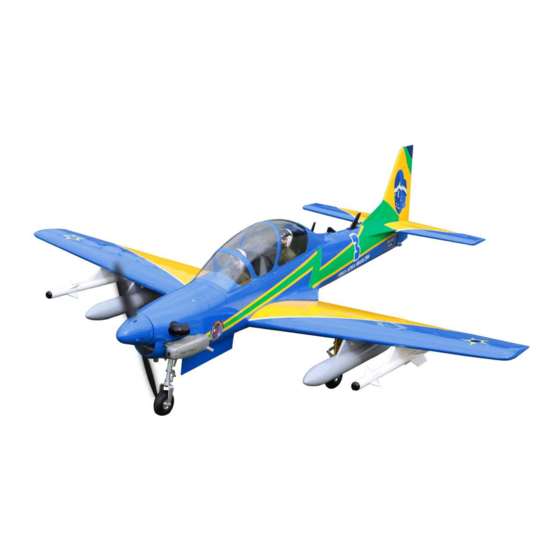
ASSEMBLY MANUAL
Speciications
Wing span-------------------- 65 in--------------- 165 cm
Wing area-------------------- 658.8 sq.in-------- 42.5 sq dm
Weight------------------------ 10.4-11 lbs-------- 4.7-5.0 kg
Length------------------------ 62.4 in------------- 158.4 cm
Engine------------------------ 0.91 -1.00 cu.in--- 2-stroke
ELECTRIC CONVERSION : OPTIONAL
Radio------------------------- 8 channels with 9 servos
Code : SEA 379
1.00-1.25 cu.in --- 4-stroke
15-26cc
1
Advertisement

Related Manuals for Seagull Models Super Tucano T-27


Summary of Contents for Seagull Models Super Tucano T-27
- Page 1 Code : SEA 379 ASSEMBLY MANUAL Speciications Wing span-------------------- 65 in--------------- 165 cm Wing area-------------------- 658.8 sq.in-------- 42.5 sq dm Weight------------------------ 10.4-11 lbs-------- 4.7-5.0 kg Length------------------------ 62.4 in------------- 158.4 cm Engine------------------------ 0.91 -1.00 cu.in--- 2-stroke 1.00-1.25 cu.in --- 4-stroke 15-26cc ELECTRIC CONVERSION : OPTIONAL Radio------------------------- 8 channels with 9 servos...
- Page 2 Super Tucano “Brazil Air Force” 65” span 15-20cc Instruction Manual. INTRODUCTION Super Tucano “Brazil Air Force” 65” span 15- hank you for choosing the 20cc Super Tucano “Brazil Air Force” 65” span ARTF by SG MODELS . he 15-20cc was designed with the intermediate/advanced sport lyer in mind. It is a semi scale airplane which is easy to ly and quick to assemble.
- Page 3 KIT CONTENTS HINGING THE FLAP Super Tucano “Brazil Air SEA379 Note : he control surfaces, including the ailer- Force” 65” span 15-20cc ons, elevators, and rudder, are prehinged with hinges installed, but the hinges are not glued in place. It is imperative that you properly adhere 1.
- Page 4 Super Tucano “Brazil Air Force” 65” span 15-20cc Instruction Manual. Repeat this process with the other wing Delect the and completely satu- panel, securely hinging the aileron in rate each hinge with thin C/A glue. he place ailerons front surface should lightly con- tact the wing during this procedure.
- Page 5 Remove each hinge from the wing panel NOTE : he hinge is constructed of a spe- and aileron and place a T-pin in the center cial material that allows the C/A to wick of each hinge. Slide each hinge into the wing or penetrate and distribute throughout panel until the T-pin is snug against the wing the hinge, securely bonding it to the wood...
- Page 6 Super Tucano “Brazil Air Force” 65” span 15-20cc Instruction Manual. Repeat this process with the other wing panel, securely hinging the aileron in place Ater both ailerons are securely hinged, irmly grasp the wing panel and aileron to make sure the hinges are securely glued and cannot be pulled out.
- Page 7 Remove the control horns from the control surfaces. Apply epoxy to the slot in the aileron and lap. Make sure the epoxy gets into the slot for a good bond between the surfaces and control horn. INSTALL FLAP CONTROL HORN Epoxy Install the lap control horn using the same method as same as the aileron con-...
- Page 8 Super Tucano “Brazil Air Force” 65” span 15-20cc Instruction Manual. Minimum servo spec. Torque : 80 oz-in (5.8 kg-cm) @ 4.8V; 100 oz-in (7.2 kg-cm) @ 6.0V Because the size of servos difer, you Epoxy may need to adjust the size of the precut opening in the mount.
- Page 9 Remove the string from the wing at the servo location and use the tape to attach it to the servo extension lead. Pull the lead through the wing and remove the string. C/A glue Use dental loss or heatshrunk tube to secure the connection so they cannot be- come unplugged.
- Page 10 Super Tucano “Brazil Air Force” 65” span 15-20cc Instruction Manual. AILERON PUSHROD INSTALLATION Set the aileron hatch in place and use a Phillips screw driver to install it with four Mark the control wire where it crosses wood screws. the servo arm hole. M3x10mm Make a 90-degree bend at the mark and cut of the excess wire leaving 8mm past...
- Page 11 Wing M2 lock nut Connect the linkage as shown and secure the control wire with a snap keeper. Flap INSTALLING RETRACTABLE LANDING GEAR Locate items necessary to install Sprin Landing Gear. You use this fork set JP ER-120-84degree. INSTALLING THE FLAP PUSHROD Repeat the procedure for the aileron pushrod.
- Page 12 Super Tucano “Brazil Air Force” 65” span 15-20cc Instruction Manual. M3x4mm M3x20mm...
- Page 13 Collar M3x4mm M3x10mm Collar M3x4mm...
- Page 14 Super Tucano “Brazil Air Force” 65” span 15-20cc Instruction Manual. WING AND THE ARMAMENTS ASSEMBLY Please see below pictures.
- Page 15 4x25mm C/A glue 4x25mm...
- Page 16 Super Tucano “Brazil Air Force” 65” span 15-20cc Instruction Manual. THROTTLE SERVO ARM INSTALLATION Install adjustable servo connector in the servo arm as same as picture below: INSTALLING THE FUSELAGE SERVOS Because the size of servos difer, you may need to adjust the size of the precut Rudder servo arm opening in the mount.
- Page 17 INSTALLING THE ENGINE SWITCH Trim and cut Vent tube Fuel pick up tube Fuel ill tube Switch Carefully bend the second nylon tube up at a 45º angle. his tube is the vent tube. Test it the stopper assembly into the tank. INSTALLING THE STOPPER It may be necessary to remove some of the ASSEMBLY...
- Page 18 Super Tucano “Brazil Air Force” 65” span 15-20cc Instruction Manual. When satisied with the alignment of the stopper assembly tighten the 3 x 20mm ma- chine screw until the rubber stopper expands and seals the tank opening. Do not over- tighten the assembly as this could cause the tank to split.
- Page 19 head locker glue Vent tube Fuel pick up tube Fuel ill tube Connect the lines from the tank to the engine and muler. he vent line will connect to the muler and the line from the clunk tothe carburetor. Blow through one of the lines to ensure the fuel lines have not become kinked inside the fuel tank compartment.
- Page 20 Super Tucano “Brazil Air Force” 65” span 15-20cc Instruction Manual. Use a drill to drill the four holes in the engine mount rails. Pushrod wire Machine screw M4x30mm 4.5mm M4 lock Nut On the ie wall has the location for the throttle pusshrod tube (pre-drill).
- Page 21 Move the throttle stick to the closed po- sition and move the carburetor to closed. Use a 2.5mm hex wrench to tighten the screw that secures the throttle pushrod wire. Make sure to use threadlock on the screw so it does not vibrate loose. COWLING Please see below pictures.
- Page 22 Super Tucano “Brazil Air Force” 65” span 15-20cc Instruction Manual. Use a drill and drill bit to drill the holes for the cowl mounting screws. Make sure the cowl position is correct before drill- ing each hole. Install the muler and muler exten- sion onto the engine and make the cutout in the cowl for muler clearance.
- Page 23 ELECTRIC POWER CONVERSION Locate the items neccessary to install the electric power conversion included with your model. Recommend the items necessary to in- stall the electric power conversion parts included with your model.
- Page 24 Super Tucano “Brazil Air Force” 65” span 15-20cc Instruction Manual. - Motor: 110 - 2000 Watts - Propeller: 17x8 ~ 19x10 - ESC: 85A - 6S- 8S Lipo Attach the electric motor box to the ire- wall centered with the cross lines drawn on the electric motor box and irewall.
- Page 25 Attach the motor to the front of the elec- tric motor box using four 4mm blind nut, Balsa stick four M4x20mm hex head bolts to secure the motor. Please see picture shown. Epoxy Attach the speed control to the side of the motor box using two-sided tape and tie wraps.
- Page 26 Super Tucano “Brazil Air Force” 65” span 15-20cc Instruction Manual. he propeller should not touch any part of the spinner cone. If it does, use a sharp modeling knife and carefully trim away the spinner cone where the propel- ler comes in contact with it. Battery NOSE GEAR INSTALLATION Locate the parts needed to attach the...
- Page 27 M3x20mm 17mm...
- Page 28 Super Tucano “Brazil Air Force” 65” span 15-20cc Instruction Manual. Epoxy Epoxy...
- Page 29 27mm...
- Page 30 Super Tucano “Brazil Air Force” 65” span 15-20cc Instruction Manual. M3x4mm...
- Page 31 Epoxy INSTALLING THE HORIZONTAL INSTALL ELEVATOR CONTROL HORN STABILIZER Using a ruler and a pen, locate the cen- terline of the horizontal stabilizer, at the trailing edge, and place a mark. Use a tri- angle and extend this mark, from back to front, across the top of the stabilizer.
- Page 32 Super Tucano “Brazil Air Force” 65” span 15-20cc Instruction Manual. Slide the stabilizer into place in the When cutting through the covering to precut slot in the rear of the fuselage. he remove it, cut with only enough pressure to stabilizer should be pushed irmly against only cut through the covering itself.
- Page 33 HINGING THE RUDDER - Glue the top two rudder hinges in place using the same techniques used to hinge the ailerons. Epoxy - he lower hinge will be glued when the i/rudder assembly is attached to the fu- selage. Rudder Fiberglass control horn INSTALLING VERTICAL STABILIZER INSTALL RUDDER CONTROL HORN Fiberglass control horn...
- Page 34 Super Tucano “Brazil Air Force” 65” span 15-20cc Instruction Manual. - Using a modeling knife, remove the cov- ering from over the precut hinge slot cut into the lower rear portion of the fuselage. Epoxy Vertical Stabilizer. Horizontal 90º Stabilizer. - Slide the vertical stabilizer back inplace.
- Page 35 Elevator and rudder pushrods assembly as pictures below. C/A glue 500mm Hinge ELEVATOR PUSHROD INSTALLATION Locate items necessaryto install rudder Elevator pushrod pushrod. M2 clevis Hex nut Fuel tubing - Install the elevator control horn using the same method as with the aileron con- trol horns.
- Page 36 Super Tucano “Brazil Air Force” 65” span 15-20cc Instruction Manual. RUDDER PUSHROD INSTALLATION - Locate items necessaryto install rudder pushrod.
- Page 37 Epoxy INSTALLATION COCKPIT, PILOT AND CANOPY Locate items necessary to install.
- Page 38 Super Tucano “Brazil Air Force” 65” span 15-20cc Instruction Manual. Epoxy...
- Page 39 Epoxy Epoxy Epoxy...
- Page 40 Super Tucano “Brazil Air Force” 65” span 15-20cc Instruction Manual. M2x6mm Epoxy...
- Page 41 ATTACKMENT WING-FUSELAGE Attach the aluminium tube into fuselage. Epoxy Wing tube INSTALLING THE BATTERY-RECEVER Plug the servos leads and the switch lead into the receiver. Plug the battery pack lead into the switch also. Wrap the receiver and battery pack in the protective foam rubber to protect them from vibration.
- Page 42 Super Tucano “Brazil Air Force” 65” span 15-20cc Instruction Manual. BALANCING 1) It is critical that your airplane be balanced correctly. Improper balance will cause your plane to lose control and crash. THE CENTER OF GRAV- ITY IS LOCATED 88MM BACK FROM THE LEADING EDGE OF THE WING AT THE WING ROOT.
- Page 43 Lit the model. If the tail drops when CONTROL THROWS you lit, the model is “tail heavy” and you must add weight* to the nose. If the nose drops, it is “nose heavy” and you must Ailerons: Rudder: add weight* to the tail to balance. High Rate : High Rate : Right : 40 mm...
- Page 44 Super Tucano “Brazil Air Force” 65” span 15-20cc Instruction Manual. FLIGHT PREPARATION. PREFLIGHT CHECK. Check the operation and direction of the 1) Completely charge your transmit- elevator, rudder, ailerons and throttle. ter and receiver batteries before your irst day of lying. A) Plug in your radio system per the 2) Check every bolt and every glue joint manufacturer’s instructions and turn eve-...
- Page 45 If you have any queries, or are interested in our products, please feel free to contact us Factory : 12/101A - Hamlet 4 - Le Van Khuong Street - Dong hanh Ward - Hoc Mon District - Ho Chi Minh City - Viet Nam. Oice : 62/8 Ngo Tat To Street - Ward 19 - Binh hanh District - Ho Chi Minh City - Viet Nam Phone : 848 - 86622289 or 848- 36018777...
Need help?
Do you have a question about the Super Tucano T-27 and is the answer not in the manual?
Questions and answers