Table of Contents
Advertisement
MS:134
ASSEMBLY MANUAL
"Graphics and specifications may change without notice".
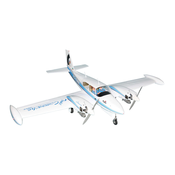
Specifications:
Wing span ----------------------------76.4in (194cm).
Wing area -----------------830.8sq.in (53.6sq dm).
Weight -------------------------10.6-11lbs (4.8-5kg).
Length ------------------------------51.3in (130.3cm).
Engine ------------------ 0.46-0.55cu.in ----2-stroke.
0.72-0.82cu.in---4-stroke.
Radio -------------------6 channels with 10 servos.
Retracts landing gear (excluded)-optional.
Electric conversion: optional.
Advertisement
Table of Contents

Related Manuals for Seagull Models TWIN COMANCHE SEA134


Summary of Contents for Seagull Models TWIN COMANCHE SEA134
- Page 1 MS:134 ASSEMBLY MANUAL “Graphics and specifications may change without notice”. Specifications: Wing span ----------------------------76.4in (194cm). Wing area -----------------830.8sq.in (53.6sq dm). Weight -------------------------10.6-11lbs (4.8-5kg). Length ------------------------------51.3in (130.3cm). Engine ------------------ 0.46-0.55cu.in ----2-stroke. 0.72-0.82cu.in---4-stroke. Radio -------------------6 channels with 10 servos. Retracts landing gear (excluded)-optional. Electric conversion: optional.
-
Page 2: Kit Contents
TWIN COMANCHE INTRODUCTION. Thank you for choosing the TWIN COMANCHE ARTF by SEAGULL MODELS. The TWIN COMANCHE was designed with the intermediate/advanced sport flyer in mind. It is a semi scale airplane which is easy to fly and quick to assemble. The airframe is conventionally built using balsa, plywood to make it stronger than the average ARTF , yet the design allows the aeroplane to be kept light. -
Page 3: Additional Items Required
www.seagullmodels.com CONTEN.TS HINGING THE FLAP . Fuselage Left wing panel Right wing panel Tail set (2) Aluminum wing tube wheel (3) Fiberglass cowl Speing landing gear EP conversion pack Hardware bag included T-pin. ADDITIONAL ITEMS REQUIRED. Hinge. 0.46-0.55 2-stroke. 0.72-0.82 4-stroke. -
Page 4: Hinging The Aileron
Instruction Manual. TWIN COMANCHE HINGING THE AILERON . Note: The control surfaces, including the ailerons, elevators, and rudder, are prehinged with hinges installed, but the hinges are not glued in place. It is imperative that you properly adhere the hinges in place per the Hinge. -
Page 5: Hinging The Rudder
www.seagullmodels.com HINGING THE RUDDER. Glue the rudder hinges in place using the same techniques used to hinge the ailerons. 5) Turn the wing panel over and deflect the aileron in the opposite direction from the opposite side. Apply thin C/A glue to each Hinge. - Page 6 Instruction Manual. TWIN COMANCHE Install plastic wing tip to wing end. 3) Once the epoxy cures and use a covering INSTALL THE AILERONS CONTROL iron to seal the covering on the wing and over HORN. the wing tip. 1) Locate the hardware necessary to install the control horns for the ailerons.
- Page 7 www.seagullmodels.com 2) Position the control horn on the bottom of the aileron. You will see pre-drill hole 3mm for the horn mounting screw on the aileron. Aileron control horn. 3mm. INSTALL FLAP CONTROL HORN. Install the flap control horn using the same method as same as the aileron control horns.
- Page 8 Instruction Manual. TWIN COMANCHE Epoxy. Horizontal Elevator Stabilizer. 18mm. Flap control horn. INSTALL ELEVATOR CONTROL HORN. Install the elevator control horn using the same method as same as the aileron control horns. Elevator control horn. 2 sets. INSTALL RUDDER CONTROL HORN. 3x35mm.
-
Page 9: Installing The Fuselage Servos
www.seagullmodels.com CONTROL HORN M3 SCREW. Rudder servo. Aluminum Washer. Epoxy. Rudder Fuselage Elevator servo. Aluminum Washer. M3 LOCK NUT THROTTLE SERVO ARM INSTALLATION. Install adjustable servo connector in the servo Epoxy. arm as same as picture below: Rudder Fuselage Loctite secure. Adjustable Servo 18mm connector. -
Page 10: Installing The Switch
Instruction Manual. TWIN COMANCHE Metal connector. Throttle servo arm. 25mm. Servo arm. Servo for retractable only. INSTALLING THE SWITCH. Rudder servo arm. Install the switch into the precut hole in the side, in the fuselage. 3/ 32” Hole. Stearing servo arm. Elevator servo arm. -
Page 11: Installing The Aileron - Flap Servos
www.seagullmodels.com INSTALLING THE AILERON - FLAP SERVOS. Servos. Small weight. Thread. 4) Apply 2-3 drops of thin C/A to each of the Because the size of servos differ, you mounting holes. Allow the C/A to cure without may need to adjust the size of the precut open- using accelerator. - Page 12 Instruction Manual. TWIN COMANCHE Aileron servo. M2x12mm. M2x12mm. Flap servo. Small weight. String. Attach the string to the servo lead and carefully thread it though the wing.
- Page 13 www.seagullmodels.com 6) A string has been provided in the wing to 1) Mark the control wire where it crosses the pull the aileron lead through to the wing root. servo arm hole. Remove the string from the wing at the servo location and use the tape to attach it to the servo extension lead.
-
Page 14: Engine Mount Installation
Instruction Manual. TWIN COMANCHE Repeat the procedure for the other aileron servo. INSTALLING THE FLAP PUSHROD. Repeat the procedure for the aileron pushrod. Flap. M2 lock nut. Wing. ENGINE MOUNT INSTALLATION. 1) Locate the items necessary to install the engine mount included with your model. + ENGINE .46- .55 : 2 STROKE. - Page 15 www.seagullmodels.com 2) Use a pin drill and 2mm drill bit to drill a small indentation in the mount for the engine mounting screw. 2mm. Epoxy. 3) Use a drill to drill the four holes in the engine mount rails. Epoxy. 2mm.
-
Page 16: Installing The Stopper Assembly
Instruction Manual. TWIN COMANCHE 3) Use a drill to drill the four holes in the engine mount rails. 2mm. Epoxy. INSTALLING THE STOPPER ASSEMBLY. 1) Using a modeling knife, carefully cut off the rear portion of one of the 3 nylon tubes leaving 1/2”... -
Page 17: Fuel Tank Installation
www.seagullmodels.com Vent tube. Fuel pick up tube. Fuel tank. Fuel fill tube. 3) Carefully bend the second nylon tube up at a 45º angle. This tube is the vent tube. 4) Test fit the stopper assembly into the tank. It may be necessary to remove some of 8) Use plywood template to hold in place the flashing around the tank opening using a the fuel tank with C/A glue to secure the fuel... -
Page 18: Mounting The Engine
Instruction Manual. TWIN COMANCHE MOUNTING THE ENGINE. COWLING. + ENGINE .46- .55 : 2 STROKE. 1) Connect the Z-bend in the 450mm throttle pushrod to the outer hole of the carburetor arm. 2) Slide the throttle pushrod wire into the tube. Position the engine between the mounts. - Page 19 www.seagullmodels.com Trim and cut. 3) Install the muffler and muffler extension onto the engine and make the cutout in the cowl for muffler clearance. Connect the fuel Trim and cut. and pressure lines to the carburetor, muffler and fuel filler valve. Secure the cowl to fuse- lage using the M3x10mm screws.
- Page 20 Instruction Manual. TWIN COMANCHE M3x10mm. + ENGINE .72- .82 : 4 STROKE. 1) Slide the pushrod tube in the firewall and guide it through the fuel tank mount. Use medium C/A to glue the tube to the firewall and the fuel tank mount. 2) Connect the Z-bend in the 450mm throttle pushrod to the outer hole of the carburetor arm.
- Page 21 www.seagullmodels.com 5) Move the throttle stick to the closed position Trim and cut. and move the carburetor to closed. Use a 2.5mm hex wrench to tighten the screw that secures the throttle pushrod wire. Make sure to use threadlock on the screw so it does not vibrate loose.
- Page 22 Instruction Manual. TWIN COMANCHE Machine screw M3x10mm. Needle valve. Epoxy. ELECTRIC POWER CONVERSION. 1) Locate the items neccessary to install the electric power conversion included with your model.
- Page 23 www.seagullmodels.com - Model size: .35-.45 size models - Motor: 35mm 830 rev per volt - Propeller: 10x7 - ESC: 50A - Lipo Batteries: 4 cell 3200mA 2) Attach the electric motor box to the firewall suitable with the cross lines drawn on the electric motor box and firewall.
-
Page 24: Installing The Spinner
Instruction Manual. TWIN COMANCHE Blind nut. Speed control. Electric motor. Battery M4 x 15mm. INSTALLING THE SPINNER. Epoxy. Install the spinner backplate, propeller and spinner cone. 150mm. The propeller should not touch any part of the spinner cone. If it does, use a sharp modeling knife and carefully trim away Balsa stick. - Page 25 www.seagullmodels.com + ENGINE .72- .82 : 4 STROKE. Epoxy. Pen. INSTALLING TEXTURED LANDING GEAR. 2mm. M3x15mm. Cut.
- Page 26 Instruction Manual. TWIN COMANCHE Screw. Epoxy. Epoxy. Epoxy. Epoxy.
- Page 27 www.seagullmodels.com Cut. 3) Glue hardwood mounting blocks into the Repeat the procedure for the other wing. wing as show with epoxy. INSTALLING RETRACTABLE Epoxy. LANDING GEAR (OPTIONAL). 1) Locate the items necessary to install the retracts landing gear and retract linkage instal- lation (excluded).
- Page 28 Instruction Manual. TWIN COMANCHE M3x15mm. M2 lock nut. M2 clevis. 6) Install the wheel wells after adjusting the retracts. Roughen the bottom side of the well and glue the wells using C/A glue as shown. C/A glue. Epoxy. 7) Install the gear door to the retract strut. Apply a thin epoxy to the two gear door brack- ets to secure the gear door to the retract strut as shown.
- Page 29 www.seagullmodels.com Excluded. Repeat the procedure for the other wing. INSTALLING NOSE RETRACTABLE LANDING GEAR (OPTIONAL). Metal connector. 25mm. Servo arm. Servo for retractable only. C/A glue.
- Page 30 Instruction Manual. TWIN COMANCHE C/A glue. 2mm. 2mm.
- Page 31 www.seagullmodels.com INSTALLING NOSE TEXTURED LANDING GEAR. M2 clevis. Adjustable connector.
-
Page 32: Installing The Horizontal Stabilizer
Instruction Manual. TWIN COMANCHE Remove the covering. Cut. 3) Put the stabilizer into place in the position of the fuselage. 4) Install the stabilizer onto the fuselage. Align the centerline drawn on the top and the rear of the stabilizer with the centre of the fu- selage. -
Page 33: Installing The Vertical Stabilizer
www.seagullmodels.com Remove the covering. When cutting through the covering to remove it, cut with only enough pressure to only cut through the covering itself. Cut- ting into the balsa structure may weaken 10) After the epoxy has fully cured, re- 8) Using a modeling knife, carefully re- move the masking tape or T-pins used to hold move the covering that overlaps the stabilizer... - Page 34 Instruction Manual. TWIN COMANCHE Fill epoxy. While holding the vertical stabilizer Epoxy. firmly in place, use a pen and draw a line on each side of the vertical stabilizer where it meets the top of the fuselage. 4) When you are sure that everything is aligned correctly, mix up a generous amount of Flash 30 Minute Epoxy.
- Page 35 www.seagullmodels.com ELEVATOR PUSHROD HORN INSTALLATION. 1) Install the elevator control horn using the same method as with the aileron control horns. 2) Position the elevator control horn on the both side of elevator. Rudder control horn. Elevator control horn. C/A glue. 3) Thread one clevis and M2 lock nut on to each elevator control rod.
- Page 36 Instruction Manual. TWIN COMANCHE RUDDER PUSHROD HORN INSTALLATION. Elevator pushrod. M2 lock nut . M2 clevis. 8mm. Pen. Control horn. Rudder pushrod. 8mm. M2 lock nut. Metal clevis. 8mm. Pen. 8mm. Cut.
-
Page 37: Apply The Decals
www.seagullmodels.com Screw. Battery. APPLY THE DECALS. 1) If all the decals are precut and ready to stick. Please be certain the model is clean and free from oily fingerprints and dust. Position decal on the model where desired, using the photos on the box and aid in their location. - Page 38 Instruction Manual. TWIN COMANCHE ATTACHMENT WING-FUSELAGE. Attach the aluminium tube into fuselage. Wing tube. Receiver. Insert two wing panels as pictures below. INSTALL THE PLASTIC PARTS. Epoxy. Wing bolt.
- Page 39 www.seagullmodels.com Open Position. servo arm. Close Position. 12mm. servo arm.
-
Page 40: Control Throws
Instruction Manual. TWIN COMANCHE With the wing attached to the fuselage, all parts of the model installed ( ready to fly), and empty fuel tanks, hold the model at the marked balance point with the stabilizer level. Lift the model. If the tail drops when you lift, the model is “tail heavy”... -
Page 41: Flight Preparation
www.seagullmodels.com FLIGHT PREPARATION. PREFLIGHT CHECK. 1) Completely charge your transmitter A) Check the operation and direction of and receiver batteries before your first day of the elevator, rudder, ailerons and throttle. flying. Plug in your radio system per the 2) Check every bolt and every glue joint manufacturer's instructions and turn every- in the TWIN COMANCHE to ensure that ev- thing on. - Page 42 Instruction Manual. TWIN COMANCHE FOR USA MARKET ONLYLY. Safety,Precautions and Warnings As the user of this product, you are solely responsible for operating it in a manner that does not endanger yourself and others or result in damage to the product or the property of others. Carefully follow the directions and warnings for this and any optional support equipment (chargers, rechargeable battery packs, etc.) that you use.
- Page 43 www.seagullmodels.com If you as the Purchaser or user are not prepared to accept the liability associated with the use of this Product, you are advised to return this Product immediately in new and unused condition to the place of purchase. Law: These Terms are governed by Illinois law (without regard to conflict of law principals).
Need help?
Do you have a question about the TWIN COMANCHE SEA134 and is the answer not in the manual?
Questions and answers