Table of Contents
Advertisement
WWW.SEAGULLMODELS.COM
A S S E M B L Y M A N U A L
Code: SEA240
" Graphics and specifications may change without notice ".
(SEA240M)
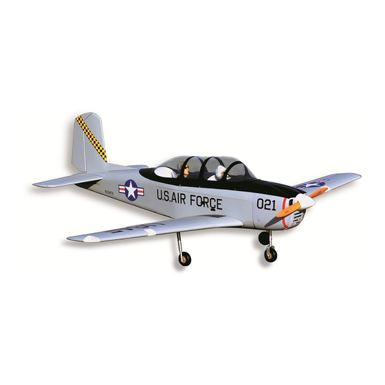
Specifications:
Wingspan---------------74.8 in (190 cm).
Wing area---------------848.5 sq.in ( 54.7sq.dm).
(SEA240Y)
Weight-------------------11.2 lbs ( 5.1 kg).
Length-------------------56.3 in (143 cm).
Engine-------------------20-22cc
----------------------------Power 110
Radio--------------------6 channels with 11 servos.
Electric conversion: Optional.
www.seagullmodels.com
1
Advertisement
Table of Contents

Related Manuals for Seagull Models T-34 Mentor


Summary of Contents for Seagull Models T-34 Mentor
- Page 1 WWW.SEAGULLMODELS.COM A S S E M B L Y M A N U A L Code: SEA240 “ Graphics and specifications may change without notice ”. (SEA240M) Specifications: Wingspan---------------74.8 in (190 cm). Wing area---------------848.5 sq.in ( 54.7sq.dm). (SEA240Y) Weight-------------------11.2 lbs ( 5.1 kg). Length-------------------56.3 in (143 cm).
-
Page 2: Kit Contents
MENTOR is simply a joy. This instruction manual is designed to help you build a great flying aeroplane. Please read this manual throughly before starting assembly of your T-34 MENTOR . Use the parts listing below to indentify all parts. -
Page 3: Additional Items Required
WWW.SEAGULLMODELS.COM HINGING THE FLAP. KIT CONTENTS. SEA240 T-34 MENTOR Note : The control surfaces, including the ai- SEA24001 Fuselage lerons, elevators, and rudder, are prehinged SEA24002 Wing set with hinges installed, but the hinges are not glued in place. It is imperative that you prop-... -
Page 4: Hinging The Aileron
T-34 MENTOR Instruction Manual. 4) Deflect the flap and completely saturate 8) After both flap are securely hinged, firmly each hinge with thin C/A glue. The flap’s grasp the wing panel and flap to make sure front surface should lightly contact the wing the hinges are securely glued and cannot during this procedure. -
Page 5: Hinging The Elevator
WWW.SEAGULLMODELS.COM 5) Turn the wing panel over and deflect the aileron in the opposite direction from the opposite side. Apply thin C/A glue to each hinge, making sure that the C/A penetrates into both the aileron and wing panel. 6) Using C/A remover/debonder and a pa- Hinge. -
Page 6: Hinging The Rudder
T-34 MENTOR Instruction Manual. HINGING THE RUDDER. INSTALL FLAP CONTROL HORN. Glue the rudder hinges in place using Install the flap control horn using the the same techniques used to hinge the ai- same method as same as the aileron con- lerons. -
Page 7: Installing The Fuselage Servos
WWW.SEAGULLMODELS.COM Elevator fiberglass control horn. INSTALLING THE FUSELAGE SERVOS. Because the size of servos differ, you may need to adjust the size of the precut opening in the mount. The notch in the sides of the mount allow the servo lead to pass through. -
Page 8: Installing The Switch
T-34 MENTOR Instruction Manual. INSTALLING THE SWITCH . Install the switch into the precut hole in the side, in the fuselage. 3/32” Hole. Trim and cut. Switch. Vent tube. Fuel pick up tube. INSTALLING THE STOPPER ASSEMBLY. Fuel fill tube. -
Page 9: Fuel Tank Installation
WWW.SEAGULLMODELS.COM 5) With the stopper assembly in place, the weighted pick-up should rest away from the rear of the tank and move freely inside the tank. The top of the vent tube should rest just below the top of the tank. It should not touch the top of the tank. -
Page 10: Engine Mount Installation
T-34 MENTOR Instruction Manual. 2) Use a pin drill and 4mm drill bit to ENGINE MOUNT INSTALLATION. drill a small indentation in the mount for the engine mounting screw. 1) Locate the items necessary to install the engine mount included with your model. - Page 11 WWW.SEAGULLMODELS.COM 8) Reinstall the servo horn by sliding the connector over the pushrod wire. Center the throttle stick and trim and install the servo horn perpendicular to the servo center line. Machine screw M4x30mm Pushrod wire. 9) Move the throttle stick to the closed po- sition and move the carburetor to closed.
- Page 12 T-34 MENTOR Instruction Manual. Because of the size of the cowl, it may be nec- essary to use a needle valve extension for the high speed needle valve. Make this out of suf- ficient length 1.5mm wire and install it into the end of the needle valve.
- Page 13 WWW.SEAGULLMODELS.COM ELECTRIC POWER CONVERSION. 1) Locate the items neccessary to install the electric power conversion included with your model. M4x20mm 4) Attach the motor to the front of the electric motor box using four 4mm blind nut, four M3x12mm hex head bolts to se- cure the motor.
- Page 14 T-34 MENTOR Instruction Manual. 4 mm Balsa stick. Epoxy 6) Attach the speed control to the side of the motor box using two-sided tape and tie wraps. Connect the appropriate leads from the speed control to the mo- tor. Make sure the leads will not interfere with the operation of the motor.
-
Page 15: Installing The Spinner
WWW.SEAGULLMODELS.COM INSTALLING THE SPINNER. Servos Small weight Thread Because the size of servos differ, you may need to adjust the size of the precut opening in the mount. The notch in the sides of the mount allow the servo lead to pass through. - Page 16 T-34 MENTOR Instruction Manual. 8) Remove the string from the wing at the servo location and use the tape to at- tach it to the servo extension lead. Pull the lead through the wing and remove C/A glue 5) Use dental floss to secure the connec- tion so they cannot become unplugged.
-
Page 17: Installing The Aileron Servo
WWW.SEAGULLMODELS.COM INSTALLING THE FLAP SERVO. Repeat the procedure for the flap servo. 9) Set the aileron hatch in place and use a Phillips screw driver to install it with four wood screws. INSTALLING THE LIGHT COVER. Please see below pictures. 2x10mm INSTALLING THE AILERON SERVO. - Page 18 T-34 MENTOR Instruction Manual. CA glue CA glue. AILERON PU SHROD HORN INSTALLATION. Please see below pictures.
- Page 19 WWW.SEAGULLMODELS.COM Use a felt tip pen to mark the wire where INSTALLING THE FLAP PUSHROD. it crosses the hole. Use a pair of pliers to put a shrp 90-degree bend in the wire at Repeat the procedure for the aileron the mark.
- Page 20 T-34 MENTOR Instruction Manual. Collar. Collar. M3x15mm...
- Page 21 WWW.SEAGULLMODELS.COM Repeat steps to install the retract land- ing gear at the back of the fuselage. M3x15mm Crimp. M3 clevis. Metal connector. Cable end.
-
Page 22: Optional Retractable Landing Gear
Collar. popular add-on as optional. If you want to use retracts in your T-34 Mentor, we recommend that you buy a good set of electric retracts as the Himark AM05 Main Gear and the AM-06 Nose Gear shown as below. - Page 23 WWW.SEAGULLMODELS.COM M3x15mm...
- Page 24 T-34 MENTOR Instruction Manual. Collar. Install the retract nose gear in the fu- selage. We recommend you use a sep- arate mini-size servo to steer the nose wheel, as shown. (The steering servo, pushrod, and plywood for mount are not provided.)
-
Page 25: Installing The Horizontal Stabilizer
WWW.SEAGULLMODELS.COM INSTALLING THE HORIZONTAL STABILIZER. 1) Using a ruler and a pen, locate the cen- terline of the horizontal stabilizer, at the trailing edge, and place a mark. Use a tri- angle and extend this mark, from back to front, across the top of the stabilizer. Also extend this mark down the back of the trailing edge of the stabilizer. -
Page 26: Installing Vertical Stabilizer
T-34 MENTOR Instruction Manual. 6) Using a modeling knife, carefully re- INSTALLING VERTICAL STABILIZER move the covering that overlaps the sta- bilizer mounting platform sides in the fuselage. Remove the covering from both the top and the bottom of the platform sides. -
Page 27: Installation
WWW.SEAGULLMODELS.COM Vertical Stabilizer. Rudder control horn. Horizontal 90º Stabilizer. 4) When you are sure that everything is aligned correctly, mix up a generous amount of 30 Minute Epoxy. Apply a thin layer to the bottom of the vertical stabi- 2) Rudder pushrods assembly as pictures lizer mounting area. - Page 28 T-34 MENTOR Instruction Manual. M2 clevis. M2 lock nut. Fuel tubing. Rudder pushrod. ELEVATOR PU SHROD H ORN INSTALLATION. 1) Locate items necessary to install eleva- tor pushrod. Elevator control horn. 2) Elevator pushrods assembly as pic- tures below.
- Page 29 WWW.SEAGULLMODELS.COM If you are going to install a pilot figure, Repeat steps to install the remaining el- please use a sanding bar to sand the base evator pushrod horn. of the figure so that it is flat. 3) Position the pilot figure on the can- opy floor as shown.
-
Page 30: Apply The Decals
T-34 MENTOR Instruction Manual. APPLY THE DECALS. ATTACHMENT WING- FUSELAGE. 1) If all the decals are precut and ready to Slide the aluminum tube into fuselage. stick. Please be certain the model is clean and free from oily fingerprints and dust. - Page 31 WWW.SEAGULLMODELS.COM BALANCING. 1) It is critical that your airplane be balanced correctly. Improper balance will cause your plane to lose control and crash. THE CENTER OF GRAV- ITY IS LOCATED 120MM BACK FROM THE LEADING EDGE OF THE WING AT THE WING ROOT. 2) Mount the wing to the fuselage.
-
Page 32: Control Throws
T-34 MENTOR Instruction Manual. With the wing attached to the fuselage, all parts of the model installed ( ready to fly), and empty fuel tanks, hold the mod- 120mm el at the marked balance point with the stabilizer level. Lift the model. If the tail drops when you lift, the model is “tail heavy”... -
Page 33: Flight Preparation
A) Plug in your radio system per the 2) Check every bolt and every glue manufacturer’s instructions and turn joint in the T-34 MENTOR to en- everything on. sure that everything is tight and well bonded.
Need help?
Do you have a question about the T-34 Mentor and is the answer not in the manual?
Questions and answers