Table of Contents
Advertisement
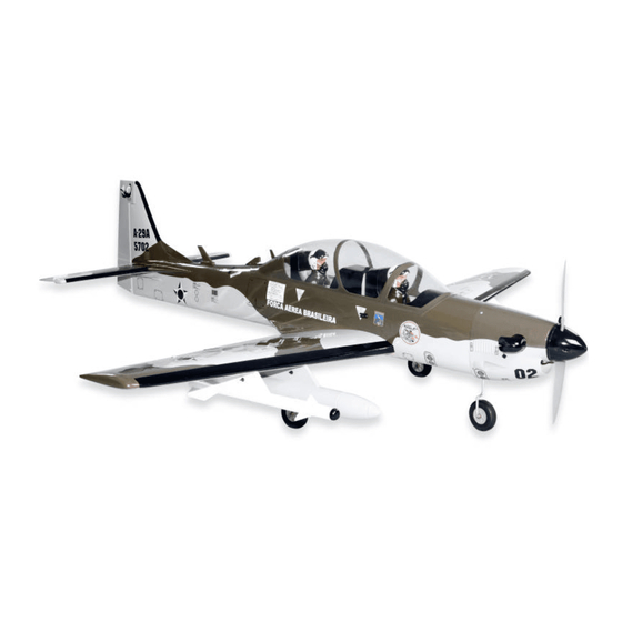
MS:124
ASSEMBLY MANUAL
"Graphics and specifications may change without notice".
Specifications:
Wing span ------------------------------65in (165cm).
Wing area -----------------658.8sq.in (42.5sq dm).
Weight -------------------------10.4-11lbs (4.7-5kg).
Length ------------------------------62.4in (158.4cm).
Engine ---------------- 0.91-1.00cu.in ----2-stroke.
1.00-1.25cu.in ----4-stroke.
Radio --------------------6 channels with 9 servos.
Retracts landing gear (included).
Advertisement
Table of Contents

Related Manuals for Seagull Models SUPER TUCANO


Summary of Contents for Seagull Models SUPER TUCANO
- Page 1 MS:124 ASSEMBLY MANUAL “Graphics and specifications may change without notice”. Specifications: Wing span ------------------------------65in (165cm). Wing area -----------------658.8sq.in (42.5sq dm). Weight -------------------------10.4-11lbs (4.7-5kg). Length ------------------------------62.4in (158.4cm). Engine ---------------- 0.91-1.00cu.in ----2-stroke. 1.00-1.25cu.in ----4-stroke. Radio --------------------6 channels with 9 servos. Retracts landing gear (included).
-
Page 2: Kit Contents
You will find that most of the work has been done for you already.The motor mount has been fitted and the hinges are pre-installed . Flying the SUPER TUCANO is simply a joy. This instruction manual is designed to help you build a great flying aeroplane. Please read this manual thoroughly before starting assembly of your SUPER TUCANO. -
Page 3: In The Box
www.seagullmodels.com KIT CONTENTS. HINGING THE AILERONS . Note: The control surfaces, including the Fuselage ailerons, elevators, and rudder, are Canopy prehinged with hinges installed, but Left wing panel the hinges are not glued in place. It Right wing panel is imperative that you properly Tail set adhere the hinges in place per the Aluminum wing tube... -
Page 4: Instruction Manual
Instruction Manual. SUPER TUCANO Hinge. 4)Deflect the aileron and completely saturate each hinge with thin C/A glue. The ailerons front surface should lightly contact the wing during this procedure. Ideally, when the hinges are glued in place, a 1/64” gap or less will be maintained throughout the lengh of the aileron to the wing panel hinge line. -
Page 5: Hinging The Elevator
www.seagullmodels.com HINGING THE ELEVATOR. Glue the elevator hinges in place using the same techniques used to hinge the ailerons. 3mm. HINGING THE RUDDER. Place epoxy into hole. This will harden the threads and prevent the crews from pulling Glue the rudder hinges in place using the loose. - Page 6 Instruction Manual. SUPER TUCANO INSTALL FLAP CONTROL HORN. T-pin. Install the flap control horn using the same method as same as the aileron control horns. C/A glue. 2 sets. 3x30mm. T-pin. C/A glue. C/A glue. Hinge. CONTROL HORN M3 SCREW.
- Page 7 www.seagullmodels.com 3mm. CONTROL HORN M3 SCREW. 3mm. Aluminum Washer. Epoxy. Horizontal Elevator Stabilizer. CONTROL HORN M3 SCREW. Aluminum Washer. M3 LOCK NUT Aluminum Washer. Epoxy. Epoxy. Rudder Fuselage Horizontal Elevator Stabilizer. Aluminum Washer. 18mm M3 LOCK NUT Epoxy. Rudder Fuselage 18mm Elevator control horn.
-
Page 8: Engine Mount Installation
Instruction Manual. SUPER TUCANO ENGINE MOUNT INSTALLATION. 1) Locate the items necessary to install the engine mount included with your model. . 4x30mm. 2) Use four 4x30mm head bolts and four 4mm washers to attach the engine mount rails to the firewall. -
Page 9: Fuel Tank Installation
www.seagullmodels.com 7) Slide the fuel tank into the fuselage. Guide the lines from the tank through the hole in the firewall. Fuel tank. Vent tube. Fuel pick up tube. Fuel fill tube. 3) Carefully bend the second nylon tube 8) Use plywood template to hold in place up at a 45º... -
Page 10: Installing The Fuselage Servos
Instruction Manual. SUPER TUCANO THROTTLE SERVO ARM INSTALLATION. Install adjustable servo connector in the servo arm as same as picture below. Adjustable servo connector. Loctile Servo arm. secure. Elevator servo.arm Blow through one of the lines to en- sure the fuel lines have not become kinked inside the fuel tank compartment. -
Page 11: Installing The Switch
www.seagullmodels.com Adjustable servo connector. Screw. Adjustable servo connector. M3x10mm. INSTALLING THE SWITCH. Install the switch into the precut hole in the side, in the fuselage. 3/ 32” Hole. Screw. -
Page 12: Mounting The Engine
Instruction Manual. SUPER TUCANO 3) Use a drill to drill the four holes in the engine mount rails. Trim and cut. 4.5mm. 4) On the fire wall has the location for the throttle pusshrod tube (pre-drill). Switch. MOUNTING THE ENGINE. - Page 13 www.seagullmodels.com COWLING. 1) Slide the fiberglass cowl over the en- gine and line up the back edge of the cowl with the marks you made on the fuselage then trim and cut as shown. Trim and cut. 8) Reinstall the servo horn by sliding the connector over the pushrod wire.
-
Page 14: Installing The Spinner
Instruction Manual. SUPER TUCANO 2) While keeping the back edge of the INSTALLING THE SPINNER. cowl flush with the marks, align the front of Install the spinner backplate, propeller and the cowl with the crankshaft of the engine. The spinner cone. - Page 15 www.seagullmodels.com 1) Using a small weight ( 5) Use dental floss to secure the connection Weighted fuel pick-up ) and string, feed the string through so they cannot become unplugged. works well the wing as indicated. Small weight. String. 2) Place the servo between the mounting 6) Secure the servo to the aileron hatch using blocks and space it from the hatch.
- Page 16 Instruction Manual. SUPER TUCANO M2x6mm. Aileron servo. M2x6mm. Flap servo. Small weight. Wing rib. Attach the string to the servo lead and carefully thread it though the wing. String. Aileron servo. Flap servo.
- Page 17 www.seagullmodels.com 2) Make a 90-degree bend at the mark and cut AILERON PUSHROD HORN INSTALLATION off the excess wire leaving 8mm past the bend. Metal clevis. M2 lock nut. Mark. Snap keeper. Pen. Servo arm. 1) Mark the control wire where it crosses the servo arm hole.
- Page 18 Instruction Manual. SUPER TUCANO INSTALLING THE FLAP PUSHROD. Repeat the procedure for the aileron pushrod. Wing. M2 lock nut. Cut. Flap. 3) Glue hardwood mounting blocks into the wing as show with epoxy. INSTALLING RETRACTABLE LANDING GEAR. 1) Locate the items necessary to install the retracts landing gear and retract linkage instal- lation.
- Page 19 www.seagullmodels.com 5) Install the linkage into the connector on the end of the retract unit as shown. Mounting the landing gear to the rail with four M3x 25mm. M3x25mm. Cut. 6) Install a wheel and two wheel collars on the main landing gear. Secure the collars. C/A glue.
- Page 20 Instruction Manual. SUPER TUCANO WNG AND THE ARMAMENTS ASSEMBLY. Plactic screw. Plactic screw.
-
Page 21: Installing The Horizontal Stabilizer
www.seagullmodels.com 5) When you are satisfied with the align- ment, hold the stabilizer in place with T- pins or masking tape, but do not glue at this time. INSTALLING THE HORIZONTAL STABILIZER. 1) Using a ruler and a pen, locate the centerline of the horizontal stabilizer, at the Hinge slot. - Page 22 Instruction Manual. SUPER TUCANO 9) When you are sure that everything is aligned correctly, mix up a generous amount of 30 Minute Epoxy. Apply a thin layer to the bottom of the stabilizer mounting area and to the stabilizer mounting platform sides in the fuselage.
-
Page 23: Installing The Vertical Stabilizer
www.seagullmodels.com 3) Slide the vertical stabilizer back in INSTALLING THE VERTICAL STABILIZER. place. Using a triangle, check to ensure that the vertical stabilizer is aligned 90º to the hori- zontal stabilizer. Vertical Stabilizer. Horizontal 90º Stabilizer. Hinge. 1) Using a modeling knife, remove the covering from over the precut hinge slot cut into the lower rear portion of the fuselage. - Page 24 Instruction Manual. SUPER TUCANO ELEVATOR - RUDDER PUSHROD HORN INSTALLATION. 1) Install the elevator control horn using the same method as with the aileron control horns. Epoxy. 2) Position the elevator control horn on the both side of elevator. Elevator control horn.
- Page 25 www.seagullmodels.com Pen. Elevator pushrod. Control horn. M2 lock nut. Metal clevis. 8mm. Elevator pushrod. 8mm. 8mm. RUDDER PUSHROD HORN INSTALLATION. M2 lock nut . M2 clevis. 8mm.
- Page 26 Instruction Manual. SUPER TUCANO Elevator pushrod. Elevator pushrod. Control horn. M2 lock nut. Rudder pushrod. Metal clevis. C/A glue. Rudder pushrod. Elevator pushrod. C/A glue. Elevator control horn. Rudder control horn. 2) Install servos arm to servos. Notice the position of the servo arms on the servos. See picture below.
- Page 27 www.seagullmodels.com MOUNTING THE NOSE WHEEL. Locate items necessary to install nose wheel. M3x25mm. M3x25mm. M2x12mm. Wheel. M3x25mm. Landing gear. Cut. 50mm. Wheel. 70mm. 2mm.
- Page 28 Instruction Manual. SUPER TUCANO Screw. Screw. Cut. 4mm. 205mm. 90mm. 225mm. Screw.
- Page 29 www.seagullmodels.com Screw. M3x25mm.
- Page 30 Instruction Manual. SUPER TUCANO INSTALLTION PILOT AND CANOPY. 1) Locate items necessary to install pilot, cockpit panel, and canopy. M2x6mm. 2) A scale pilot is included with this ARF. The Seagull Pilot included fitting well to the cockpit. (or you can order others scale pilot figures made by Seagull factory.
- Page 31 www.seagullmodels.com 4) Position the canopy onto the fuselage. Trace around the canopy and onto the fuselage using a felt-tipped pen. - Apply a bead of canopy glue around the inside edge of the canopy. Position the canopy onto the hatch. Use tape to hold the canopy secure until the glue fully cures.
-
Page 32: Apply The Decals
Instruction Manual. SUPER TUCANO Insert two wing panels as pictures below. APPLY THE DECALS. 1) If all the decals are precut and ready to stick. Please be certain the model is clean and free from oily fingerprints and dust. Position decal on the model where desired, using the photos on the box and aid in their location. -
Page 33: Control Throws
www.seagullmodels.com With the wing attached to the fuselage, all parts of the model installed ( ready to fly), and empty fuel tanks, hold the model at the marked balance point with the stabilizer level. Lift the model. If the tail drops when you lift, the model is “tail heavy”... -
Page 34: Flight Preparation
A) Plug in your radio system per the 2) Check every bolt and every glue joint manufacturer's instructions and turn every- in the SUPER TUCANO to ensure that thing on. everything is tight and well bonded. B) Check the elevator first. Pull back 3) Double check the balance of the air- on the elevator stick.
Need help?
Do you have a question about the SUPER TUCANO and is the answer not in the manual?
Questions and answers