Table of Contents
Advertisement
Advertisement
Table of Contents

Subscribe to Our Youtube Channel
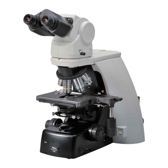
Related Manuals for Nikon Eclipse Ni-U


Summary of Contents for Nikon Eclipse Ni-U
- Page 1 M570 E 11.8.NF.1 (2/2) Upright Microscope Instruction Manual Assembly/Maintenance...
-
Page 3: Introduction
Introduction Thank you for purchasing a Nikon product. This instruction manual is written for users of the Nikon ECLIPSE Ni-U microscope. To ensure correct usage, read this manual carefully before operating this product. ● No part of this manual may be reproduced or transmitted in any form without prior written permission from Nikon. -
Page 4: Contents Of The Manual
Introduction Contents of the Manual The instruction manual for ECLIPSE Ni-U is provided as two volumes. Operation Assembly/Maintenance (This manual) Safety Precautions Assembly Components Troubleshooting Microscopy Procedures Maintenance and Storage Operation Flowchart Specifications Bright/Dark-field Microscopy Before reading the “Assembly/Maintenance” manual, Epi-fluorescence Microscopy read the “Safety Precautions”... -
Page 5: Summary Of Contents
Summary of Contents Summary of Contents (See the next page for the detailed contents.) Assembly Introduction Contents of the Manual Symbols Used in This Manual Troubleshooting Maintenance and Storage Specifications... -
Page 6: Table Of Contents
Introduction ......................... i Contents of the Manual ....................ii Symbols Used in This Manual ..................ii Summary of Contents ....................... iii Assembly....................1 ECLIPSE Ni-U System Configuration ...............2 Components List .......................3 Assembly Method......................4 Introduction ........................4 Check the input voltage..................4 Attach the DIA motorized shutter (optional)............5 Attach the lamp. - Page 7 Contents Phase Contrast Microscopy ................32 Electrical Requirements ..................33 General......................33 Epi-fluorescence Microscopy ................34 Maintenance and Storage ..............35 Replacing the Lamp ....................36 Cleaning ........................37 Cleaning Lenses....................37 Cleaning Parts Other than the Lens..............37 Cleaning Immersion Oil..................38 Decontaminating the Product................
- Page 8 Contents...
-
Page 9: Assembly
Chapter Assembly This chapter contains an Ni-U system configuration diagram, a list of its components, and explains how to assemble the system. Read appropriate notes such as CAUTION “9 Cautions on assembling and installing the product” at the beginning of the separately provided instruction manual “Operation”... -
Page 10: Eclipse Ni-U System Configuration
Chapter 1 Assembly ECLIPSE Ni-U System Configuration Camera cable to ENG mount camera DS-U3 or DS-L3 C mount camera Various adapters Photomicrography device DS camera head CFI eyepiece Centering telescope DSC port for ergonomic Tube adapter for TV adapter binocular tube... -
Page 11: Components List
The ECLIPSE Ni-U components are shown in the table below. Depending on when you purchased the ECLIPSE Ni-U, there may be devices not yet available for use and devices not listed that are already available for use. Contact your nearest Nikon representative for details. -
Page 12: Assembly Method
Be sure to turn off the power to the microscope and peripheral devices before starting cable connection. Cable connections are described in each assembly step. Nikon recommends connecting cables at the end of the assembly. See “20 Connect the motorized device cable.” for the connector connections. -
Page 13: Attach The Dia Motorized Shutter (Optional)
Assembly Attach the DIA motorized shutter (optional). The motorized shutter is attached by Nikon. Contact your nearest Nikon representative when the DIA motorized shutter needs to be attached or removed. Attach the lamp. Tool: Hex wrench (3 mm across flats) -
Page 14: Attach The Standard Arm/Contact Arm
Chapter 1 Assembly Attach the standard arm/contact arm. The attachment procedure is the same for standard arm and contact arm. To use the motorized accessories, attach the contact arm. The contact arm has a contact. When attaching a motorized device on the arm, remove the contact cover beforehand. -
Page 15: Attach The Epi-Fluorescence Cube Turret And Epi-Fluorescence Attachment (Required For Epi-Fluorescence Microscopy)
Chapter 1 Assembly Attach the epi-fluorescence cube turret and epi-fluorescence attachment (required for epi-fluorescence microscopy). Tool: Hex driver (2 mm across flats) Hex wrench (3 mm across flats) Epi-fluorescence First, connect the epi-fluorescence cube turret and Positioning hole cube turret epi-fluorescence attachment and then attach them on the Epi-fluorescence attachment... -
Page 16: Attaching A Filter Cube
Chapter 1 Assembly ■ Attaching a filter cube Precautions for attaching and removing the cube • Be sure to check that the light source is turned off before attaching or removing the cube. Be sure to check that the power switch for microscope main body is turned off and then attach the cube by •... -
Page 17: Replacing Excitation And Barrier Filters
• The filter is two-faced. Be aware that the filter does not face a wrong side. Nikon filters have an arrow indication printed on the outer frame. Make sure that the arrow faces the direction of a dichroic mirror when attaching the filter. -
Page 18: Attach The Quadrocular Tilting Tube And Dsc Zooming Port For Quadrocular Tube
Fixing screw Fixing the quadrocular tube and DSC zooming port set Attach the EPI motorized shutter (optional). The motorized shutter is attached by Nikon. Contact your nearest Nikon representative when the EPI motorized shutter needs to be attached or removed. -
Page 19: Attach Eyepieces
Chapter 1 Assembly Attach eyepieces. Make sure the notch on the eyepiece side and the Notch Protrusion protrusion of the eyepiece sleeve are aligned, then insert the eyepieces. Notch on eyepiece The eyepiece has a notch to prevent rotation. When attaching, match the notch with the protrusion on the eyepiece sleeve. -
Page 20: Attach The Condenser Holder
Chapter 1 Assembly Attach the condenser holder. Attach a condenser holder to the substage. (Remove or attach the condenser holder after detaching the stage.) Tool: Hex wrench (3 mm across flats) Hook the half dovetail of the condenser holder onto the Condenser holder half dovetail groove of the lower substage and push it fixing screw... -
Page 21: Attach The Condenser
Turn the condenser focus knob until the condenser holder reaches the bottom. Fit the round dovetail of the condenser to the condenser holder so that the Nikon nameplate faces front and tighten the fixing screw of the condenser holder with a hex driver. - Page 22 Chapter 1 Assembly NI-CUD Universal Condenser Structure Replacement cover fixing screw (two) Replacement cover removed Module replacement cover Hole number Condenser Turret lens part PH module centering knob (Use the centering knob by pulling it out horizontally when centering. Otherwise, Condenser keep it folded down.) aperture...
- Page 23 Chapter 1 Assembly [Procedure for attaching the DIC module on the condenser, dark-field module, and 2-4x auxiliary lens] Holes (5), (6), and (7) have their positioning pin and module fixing screw. • First check that the tip of the module fixing screw is not inside the hole. If it is inside, place that hole into the optical path, lift the Ph module centering knob at right rear of the condenser, and turn the centering screw to loosen the module fixing screw.
- Page 24 Chapter 1 Assembly Combination of DIC slider on the objective and DIC module on the condenser (when using the NI-CUD universal condenser) Standard combination Contrast-oriented Resolution-oriented Objective DIC module on DIC slider on DIC module on DIC slider on DIC module on DIC slider on the condenser the objective...
-
Page 25: Attaching The Dic Module To Dic Condenser Oil
Chapter 1 Assembly ■ Attaching the DIC module to DIC condenser oil D-CUO is provided with two sliders. Incorporate the oil condenser-specific DIC modules [D-C DIC N2 OIL] and [D-C DIC NR OIL] to each slider. Select the DIC module appropriate for the objective. (See the next table.) To support for particular purposes, module for higher contrast or resolution are available. - Page 26 Chapter 1 Assembly Combination of DIC slider on the objective and DIC module on the condenser (when using the D-CUO DIC condenser) Standard combination Resolution-oriented Objective DIC module DIC slider DIC module DIC slider on the condenser on the objective on the condenser on the objective Plan Fluor 10X...
-
Page 27: Attach The Nosepiece
Chapter 1 Assembly Attach the nosepiece. Tool: Hex driver (2 mm across flats) Lift the nosepiece at a position slightly toward yourself than directly below the arm and attach while sliding it back. Continue sliding the nosepiece back until its front position is aligned with the front of the arm. -
Page 28: Attach The Eyelevel Riser (Optional)
Chapter 1 Assembly Attach the eyelevel riser (optional). Tool: Hex driver (2 mm across flats) Place the eyelevel riser on the arm, and tighten the fixing screws on the front of the arm using a hex driver (2 mm across flats). Eyelevel riser fixing Eyelevel riser screw... -
Page 29: [18.2] When Attaching To The Dsc Zooming Port For Quadrocular Tube
Chapter 1 Assembly 18.2 When attaching to the DSC zooming port for quadrocular tube Screw the camera head into the C mount on the Camera connection connector DSC port. Camera head Connect the camera connection connector for the C mount camera head and the camera connector for the DS-L3/DS-U3 DS camera control unit using a provided camera cable. -
Page 30: Replace The Nd Filter (Optional)
Chapter 1 Assembly Replace the ND filter (optional). Tool: Hex driver (2 mm across flats) The ND filter in the ND filter cassette of the Ni-U main Rubber cap body can be replaced as follows: Check that the microscope power switch is OFF. Press all ND filter IN/OUT switches to the “IN”... - Page 31 B) control box B) (Connect to DSC (Ni-U) on LAMP control box B or EXT.I/O on DS-L3/U3) (Connect to dia-illumination lamphouse) MODEL ECLIPSE Ni-U NIKON CORPORATION 100–240V~ TOKYO, JAPAN 9 2 0 0 0 1 1.7A 50/60Hz M A D E I N J A P A N This device complies with Part 15 of the FCC Rules.
-
Page 32: Connect The Power Cord
Chapter 1 Assembly Connect the power cord. Make sure that the microscope is turned off (the power switch is pressed to “Ο” position). Plug the power cord into the AC inlet on the microscope main body. Plug the other end of each power cord into a wall outlet. -
Page 33: Troubleshooting
If you detect problems that are not listed in the table or the problem still persists after measures are taken, turn off the device and contact your nearest Nikon representative. -
Page 34: Optical System And Operation
Chapter 2 Troubleshooting Optical System and Operation General Problem Cause Measure Dirt or dust rotates when the eyepiece is turned. Clean the eyepiece. The eyepiece is dirty. (→See Chapter 3, “2.1 Cleaning Lenses” in the “Assembly/Maintenance”.) Dirt or dust does not rotate when eyepiece is turned (1) to (5) (1) The specimen is dirty if dirt or dust moves... - Page 35 Chapter 2 Troubleshooting Problem Cause Measure Open it to the proper size. An aperture diaphragm is stopped down too far. (→See Chapter 3, “6 Adjusting the Aperture Diaphragm” in Otherwise, it is open too much. the “Operation”.) Make sure the condenser is focused and centered. The field diaphragm image is not focused on the specimen surface.
- Page 36 If the objective does not have a stopper, do not pull protection of the objective is pushed in. because the tip cannot be turned. In this case, contact your nearest Nikon representative. Screw the objective all the way in. Objective lens is attached incorrectly.
- Page 37 Chapter 2 Troubleshooting Problem Cause Measure Attach it correctly and rotate it to the click stop position. The nosepiece is not attached correctly, or has not been fully rotated to the click stop position. (→See Chapter 1, “3 Assembly Method, 14 Attach the nosepiece”...
-
Page 38: Epi-Fluorescence Microscopy
Chapter 2 Troubleshooting Epi-fluorescence Microscopy Problem Cause Measure Lack of visibility around Push the cube in to the limit. periphery of field of view. (→See Chapter 1 “3 Assembly Method, 6 Attach the Illumination is uneven The filter cube is misaligned. epi-fluorescence cube turret and epi-fluorescence across the field of view. -
Page 39: Differential Interference Contrast Microscopy
Chapter 2 Troubleshooting Differential Interference Contrast Microscopy Problem Cause Measure Rotate it to the click stop position. The universal condenser's turret is at the (→See Chapter 3 “7.2 Using the NI-CUD Universal intermediate position. Condenser (Dry)” in the “Operation”.) Push in the slider until it reaches the limit. The DIC slider is at the intermediate position for (→See Chapter 3 “7.3 Using the D-CUO DIC Condenser an oil condenser. -
Page 40: Phase Contrast Microscopy
Chapter 2 Troubleshooting Problem Cause Measure Adjust the orientation of the optical system correctly. (→See Chapter 2 “4 Differential Interference Contrast The orientation of the polarizer is incorrect. Microscopy - 14 Adjust the orientation (vibration direction) of the polarizer and analyzer” in the “Operation”.) Select the DIC module suitable for the objective used. -
Page 41: Electrical Requirements
Chapter 2 Troubleshooting Electrical Requirements General ■ Power Problem Cause Measure There is no power even Connect the cable properly. The power cord is not connected, or is though the power switch is (→See Chapter 1, “3 Assembly Method, 20 Connect the connected improperly. -
Page 42: Epi-Fluorescence Microscopy
Chapter 2 Troubleshooting ■ Motorized nosepiece Problem Cause Measure Attach it correctly. Motorized nosepiece does The motorized nosepiece is attached incorrectly. (→See Chapter 1, “3 Assembly Method, 14 Attach the not move at all. nosepiece” in the “Assembly/Maintenance”.) Objectives are mounted on rather one side of Attach objective evenly. -
Page 43: Maintenance And Storage
Chapter Maintenance and Storage This chapter describes how to replace the halogen lamp and how to clean and store the product. -
Page 44: Replacing The Lamp
Chapter 3 Maintenance and Storage Replacing the Lamp CAUTION • Beware of burns: Wait until the lamp and nearby parts have cooled (approximately 30 minutes) before replacing the lamp. • Beware of electrical shock: Turn off the power switch and unplug the power cord from the wall outlet. •... -
Page 45: Cleaning
Chapter 3 Maintenance and Storage Cleaning Clean and decontaminate the microscope and lenses in accordance with the following procedure. ■ Tools used for cleaning • Blower • Soft brush • Soft cotton cloth, lens tissue, gauze, etc. • Absolute alcohol (ethyl or methyl alcohol), medical alcohol •... -
Page 46: Cleaning Immersion Oil
• Switch off the microscope (press the power switch to the “O” position) and wait for the lamphouse to cool before covering this product with a cover. Regular Inspections (Charged) To maintain the performance of this product, Nikon recommends periodic inspections (chargeable service). Contact your nearest Nikon representative for details. -
Page 47: Specifications
Chapter Specifications... -
Page 48: Microscopy (Principles)
■ Intended user It is intended for the researchers, medical professional and those who work on experiments in the field of pathology and cytology. Performance Properties ■ Nikon Microscope ECLIPSE Ni-U Model ECLIPSE Ni-U Main body Optical system... - Page 49 Chapter 4 Specifications Tube Binocular tube (binocular section 100%) Trinocular tube F (Binocular : adapter = 100:0, 0:100) Trinocular tube T (Binocular : adapter = 100:0, 20:80, 0:100) Ergonomic tube (Binocular section 100%) (with DSC port mounted, binocular : DSC port = 50:50) Quadrocular tilting tube (Binocular : adapter = 100:0, 0:100) (with DSC port mounted, binocular : adapter : DSC port = 0:0:100)
- Page 50 PSE approved detachable power cord set, 3 conductor grounding (3 conductor grounding Type VCTF 3 x 0.75 mm , 3 m long maximum, rated at 125 VAC minimum) ■ Simple Remote Control Pad for Nikon Microscope Model NI-SRCP Connected to:...
-
Page 51: Physical Properties
Chapter 4 Specifications Physical Properties ■ Nikon Microscope ECLIPSE Ni-U Model ECLIPSE Ni-U Operating conditions Temperature: 0°C to +40°C Humidity: 60% RH max. (no condensation) Altitude: 2000 m max. Pollution degree: Degree 2 Installation: Category II Electrical shock protection class:... - Page 52 90% RH max. (no condensation) External dimensions and External dimensions: 93 (W) x 160 (H) x 220 (D) mm (excluding projections) weight Weight: 2.2 kg ■ Simple Remote Control Pad for Nikon Microscope Model NI-SRCP Operating conditions Temperature: 0°C to +40°C Humidity: 60% RH max.
Need help?
Do you have a question about the Eclipse Ni-U and is the answer not in the manual?
Questions and answers