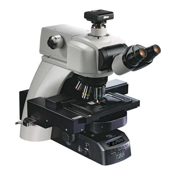
Nikon ECLIPSE Ni-E Instruction Manual
Upright motorized microscope, focusing nosepiece system
Hide thumbs
Also See for ECLIPSE Ni-E:
- Instruction manual (120 pages) ,
- Instruction manual (72 pages) ,
- Instruction manual (186 pages)

Related Manuals for Nikon ECLIPSE Ni-E


Summary of Contents for Nikon ECLIPSE Ni-E
- Page 1 M572 E 11.8.NF.1 (2/2) Upright Motorized Microscope (Focusing Nosepiece System) Instruction Manual Assembly/Maintenance...
-
Page 3: Introduction
● No part of this manual may be reproduced or transmitted in any form without prior written permission from Nikon. ● The contents of this manual are subject to change without notice. -
Page 4: Contents Of The Manual
Introduction Contents of the Manual The instruction manual for ECLIPSE Ni-E (Focusing Nosepiece System) is provided in two volumes. Operation Assembly/Maintenance (This manual) Safety Precautions Assembly Components Troubleshooting Microscopy Operations Maintenance and Storage Before Microscopy Specifications Operation Flowchart Before reading the “Assembly/Maintenance” manual, IR-DIC (Infrared Ray Differential Interference read the “Safety Precautions”... -
Page 5: Summary Of Contents
Summary of Contents Summary of Contents (See the next page for detailed contents.) Assembly Introduction Contents of the Manual Symbols Used in This Manual Troubleshooting Maintenance and Storage Specifications... -
Page 6: Table Of Contents
Contents of the Manual ....................ii Symbols Used in This Manual ..................ii Summary of Contents ....................... iii Assembly....................1 ECLIPSE Ni-E (Focusing Nosepiece System) System Configuration.......2 Components List .......................4 Assembly Method......................6 Introduction: Motorized Device Combination ..............6 Check input voltage....................7 Unfasten the elevating section................ - Page 7 Contents Troubleshooting..................29 Optical System and Operation ................30 General......................30 Differential Interference Contrast Microscopy..........33 Epi-fluorescence Microscopy ................34 Electrical System.....................35 General......................35 Epi-fluorescence Microscopy ................38 Maintenance and Storage ..............39 Replacing the Lamp ....................40 Cleaning ........................41 Cleaning Lenses....................41 Cleaning Parts Other than the Lens..............
- Page 8 Contents...
-
Page 9: Assembly
Chapter Assembly This chapter contains the system configuration diagram and components list for Ni-E (focusing nosepiece system), and instructions on assembling the system. Read appropriate notes such as CAUTION “9 Cautions on assembling and installing the product” at the beginning of the separately provided instruction manual “Operation”... -
Page 10: Eclipse Ni-E (Focusing Nosepiece System) System Configuration
Chapter 1 Assembly ECLIPSE Ni-E (Focusing Nosepiece System) System Configuration ENG mount camera C mount camera photomicrography device Camera cable to DS-U3 or DS-L3 DS camera head Various adapters Centering CFI eyepiece telescope Tube adapter for quadrocular tube Motorized shutter... - Page 11 Chapter 1 Assembly To motorized XY stage controller with driver cable Motorized XY stage Standard stage (requires motorized XY stage (requires FN1 stage Optical fiber adapter) adapter) illuminator LWD condenser To connector box with motorized shutter connector Ni-E main body Substage for focusing nosepiece Motorized...
-
Page 12: Components List
The ECLIPSE Ni-E (Focusing Nosepiece System) components are shown in the table below. Depending on when you purchased the ECLIPSE Ni-E (Focusing Nosepiece System) product, there may be products not yet available for use and products not listed that are already available for use. Contact your nearest Nikon representative for details. - Page 13 Chapter 1 Assembly Device Device Name Model Remarks To connect a second unit (on the dia-illumination side), NIE-CB must be connected to Ni-E. Motorized shutter NI-SH-E An NI-SHCS motorized shutter cable short is required for connection. Motorized shutter adapter for upright NI-SHAEP-U Shutter epi-fl...
-
Page 14: Assembly Method
Chapter 1 Assembly Assembly Method Introduction: Motorized Device Combination The available combinations are specified when installing the following four types of motorized device to Ni-E with contact arms connected. If an unallowed combination is used, an error message will be displayed when the power is turned on. -
Page 15: Check Input Voltage
Be sure to turn off the power to the microscope and peripheral devices before starting cable connection. Cable connections are described in each assembly step. Nikon recommends connecting a cable at the end of the assembly. See “20 Connect the motorized device cable” for information about connector positions. -
Page 16: Attach The Lamp
Chapter 1 Assembly Attach the lamp. Tool: Hex wrench (3 mm across flats) Insert the hex wrench and Lamp handling precautions loosen the fixing screw. Avoid touching the glass surface of the lamp with your bare hands. Fixing screw Loosen a lamphouse-cover fixing screw and lift up Lamphouse the cover to remove it. -
Page 17: Attach The Focusing Nosepiece Sub Arm
Chapter 1 Assembly Attach the focusing nosepiece sub arm. The focusing nosepiece sub arm attachment position to the elevating section of the main body differs depending on the arm spacer to be attached in step 11. NI-AMSS Arm Spacer 49 mm: Attach the sub arm to the lower position. NI-AMSL Arm Spacer 74 mm: Attach the sub arm to the upper position. -
Page 18: Attach The Polarizer Turret (Required For Differential Interference Contrast Microscopy)
Chapter 1 Assembly Attach the polarizer turret (required for differential interference contrast microscopy). Tool: Hex driver (2 mm across flats) Hex wrench (3 mm across flats) Put the polarizer turret with optical module attached (according to the following procedure) on the field lens of the microscope base and fix it using the provided fixing screws (x2). -
Page 19: Attach The Nosepiece
Chapter 1 Assembly Attach the nosepiece. The procedures are the same for both the sliding nosepiece and single nosepiece. Tool: Hex driver (2 mm across flats) Insert a hex drive through the hole on the right side of the focusing nosepiece sub arm, and then loosen the M4 hexagon hole set screw. -
Page 20: Attach The Condenser
Turn the condenser focus knob until the condenser holder of the focusing nosepiece substage reaches the bottom. Fit the round dovetail of the condenser to the condenser holder so that the Nikon nameplate faces front and tighten the condenser clamp screw of the condenser holder. Condenser... - Page 21 Chapter 1 Assembly Combination of DIC Slider on the Objective and DIC Module on the Condenser (when using FN-C LWD condenser) Standard combination Contrast-oriented Resolution-oriented DIC slider DIC slider DIC slider Objective DIC module on DIC module on DIC module on on the on the on the...
-
Page 22: Attach The Stage
Chapter 1 Assembly Attach the stage. Tools: Hex wrench (3 mm across flats) Hex wrench (4 mm across flats) 10.1 Standard stage Stage fixing screw Attaching the stage (M5 hexagon socket Remove four M5 hexagon socket head bolts head bolt) on the top of the focusing nosepiece substage. -
Page 23: [10.2] Motorized Xy Stage
Chapter 1 Assembly Attaching the stage support plates Place the support plates on the stage and Stage support tighten eight fixing screws (four for each side) Acrylic plate fixing screw chamber to secure them in place. Stage support plate Attaching a chamber holder and acrylic Chamber holder chamber... - Page 24 Chapter 1 Assembly Attaching the stage Remove the motorized XY stage cover fixing Motorized XY stage cover screws (x4) using a hex driver to remove the cover. Align the attachment hole inside the stage with the screw hole on the substage to place the stage.
- Page 25 5 6 1 0 0 1 This device complies with Part 15 of the FCC Rules.Operation is subject to the following two conditions: MODEL ECLIPSE Ni-E (1) this device may not cause harmful interference,and this device must accept any interference received, including interference...
- Page 26 Chapter 1 Assembly Pull out the fuse holder using a flathead screwdriver. This device complies with Part 15 of the FCC Rules.Operation is subject following two conditions: (1) this device may not cause harmful interference,and (2) this device must accept any interference received, including interfere that may cause undesired operation.
-
Page 27: Attach The Arm Spacer
Chapter 1 Assembly Attach the arm spacer. There are two types of arm spacers: “NI-AMSS Arm Spacer 49 mm” for the petri dish in the standard combination, and “NI-AMSL Arm Spacer 74 mm” for a thick sample such as a live mouse. The procedures are the same for both models. -
Page 28: Attach The Contact Arm/Standard Arm
Chapter 1 Assembly Attach the contact arm/standard arm. Installing the harmful light shielding block Attach the harmful light shielding block provided with the arm spacer to the contact arm/standard arm. Insert the harmful light shielding block to the bottom of the round dovetail of the arm and fix it by tightening the Harmful light shielding block fixing screw... -
Page 29: Attach The Epi-Fluorescence Cube Turret And Epi-Fluorescence Attachment (Required For Epi-Fluorescence Microscopy)
Chapter 1 Assembly Attach the epi-fluorescence cube turret and epi-fluorescence attachment (required for epi-fluorescence microscopy). Tool: Hex driver (2 mm across flats) Positioning Epi-fluorescence Hex wrench (3 mm across flats) hole cube turret Epi-fluorescence First, connect the epi-fluorescence cube turret and attachment epi-fluorescence attachment and then attach them on the microscope arm. -
Page 30: Attaching The Filter Cube/Analyzer Cube
Chapter 1 Assembly ■ Attaching the filter cube/analyzer cube Precautions on attaching and removing the cube • Be sure to check that the light source is turned off before attaching or removing the cube. • Be sure to check that the power switch for control box A is turned off and then attach the cube by rotating the cube switchover turret. -
Page 31: Replacing Excitation And Barrier Filters
Orientation of the filter • The filter is two-faced. Be aware that the filter does not face a wrong side. Nikon filters have an arrow indication printed on the outer frame. Make sure that the arrow faces the direction of a dichroic mirror when attaching the filter. -
Page 32: Attach The Quadrocular Tilting Tube And Dsc Zooming Port For Quadrocular Tube
Chapter 1 Assembly Attach the quadrocular tilting tube and DSC zooming port for quadrocular tube. Tools: Hex driver (2 mm across flats) Hex driver (2.5 mm across flats, included with DSC zooming port) Hex wrench (3 mm across flats) Hex wrench (4 mm across flats) First connect the quadrocular tilting tube and DSC zooming port for quadrocular tube and then attach them on the microscope arm (if fluorescence cube turret,... -
Page 33: Attach Eyepieces
Chapter 1 Assembly Attach eyepieces. Make sure the notch on the eyepiece side and the Notch Protrusion protrusion of the eyepiece sleeve are aligned, then insert the eyepieces. Notch on eyepiece The eyepiece has a notch to prevent rotation. When attaching, match the notch with the protrusion on the eyepiece sleeve. -
Page 34: Attach The Camera And Ds Camera Control Unit (Optional)
Chapter 1 Assembly Attach the camera and DS camera control unit (optional). 18.1 Attaching to DSC zooming port for quadrocular tube Screw the camera head into the C mount on the Camera cable connector DSC port. Camera head Connect the camera connection connector of the camera head and the camera connector of the DS-L3/DS-U3 camera control unit with dedicated camera cables. -
Page 35: Replace The Nd Filter (Optional)
Chapter 1 Assembly Replace the ND filter (optional). Tool: Hex driver (2mm across flats) The ND filter in the ND filter cassette of the Ni-E main Rubber cap body can be replaced as follows: Check that the power switch for control box A is OFF. Press all ND filter IN/OUT switches to the “IN”... -
Page 36: Connect The Power Cord
STAGE (Connect to ergo controller (Connect to or joystick controller) MICROSCOPE of motorized XY stage MODEL ECLIPSE Ni-E controller) NIKON CORPORATION 9 1 0 0 0 1 TOKYO, JAPAN M A D E I N J A P A N This device complies with Part 15 of the FCC Rules. -
Page 37: Troubleshooting
If you detect problems that are not listed in the table or the problem still persists after measures are taken, turn off the device and contact your nearest Nikon representative. -
Page 38: Optical System And Operation
Chapter 2 Troubleshooting Optical System and Operation General Problem Cause Measure Dirt or dust rotates when the eyepiece is turned. The eyepiece is dirty. Clean the eyepiece. (→See Chapter 3, “2.1 Cleaning Lenses” in the “Assembly/Maintenance”.) Dirt or dust does not rotate when the eyepiece is turned (1) to (5) (1) The specimen is dirty if dirt or dust... - Page 39 Chapter 2 Troubleshooting Problem Cause Measure Place ND filters in the optical path. The ND filters are out of the optical path. (→See Chapter 3, “3.2 Adjustment with ND Filters” in the “Operation”.) Turn the brightness control knob to Field of view is too bright. mark position and adjust the brightness The lamp voltage is too high.
- Page 40 Chapter 2 Troubleshooting Problem Cause Measure Perform diopter adjustment. Diopter adjustment has not been performed. (→See Chapter 3 “6 Adjusting the Diopter” in the A focal deviation is high “Operation”.) when switching over Make parfocal correction of the objective. objectives. Parfocal adjustment for the front and rear (→See “Operation”...
-
Page 41: Differential Interference Contrast Microscopy
Chapter 2 Troubleshooting Differential Interference Contrast Microscopy Problem Cause Measure Rotate it to the click stop position. A condenser’s turret is at the intermediate (→See “Operation” Volume, Chapter 3, “9 Using the position. Condenser”.) Attach it correctly. A DIC slider for the objective is at the (→See “Operation”... -
Page 42: Epi-Fluorescence Microscopy
Chapter 2 Troubleshooting Epi-fluorescence Microscopy Problem Cause Measure Lack of visibility around Push the cube in to the limit. periphery of field of view. (→See “Assembly/Maintenance” Volume, Chapter 1, “3 Assembly Method - 14 Attach the Illumination is uneven The filter cube is misaligned. epi-fluorescence cube turret and epi-fluorescence across the field of view. -
Page 43: Electrical System
Chapter 2 Troubleshooting Electrical System General ■ Power Problem Cause Measure The power cord is not connected, or is Connect the cable properly. There is no power even connected improperly. Or, the cable between (→See Chapter 1, “3 Assembly Method - 20 though the power switch the control box and the main body is not Connect the motorized device cable”... - Page 44 Chapter 2 Troubleshooting ■ Controls/buzzer on the main body Problem Cause Measure Change the setting. (→See “Operation” Volume, Chapter 3, “20 Buttons on the main body Operation is disabled. Operation on DS-L3” - “20.1 Setting Up the do not respond. Microscope - (3) Configuring the Button Functions - (3-1) Ni-E microscope button”.) Set the MODE function.
- Page 45 Chapter 2 Troubleshooting ■ Ergo controller and motorized XY stage ● Button Problem Cause Measure The operation button Connect the ergo controller properly. does not respond. Both (→See Chapter 1, “3 Assembly Method - 20 The ergo controller is not connected properly. LEDs on the FL-OBJ Connect the motorized device cable”...
-
Page 46: Epi-Fluorescence Microscopy
- ■Attaching the filter cube/analyzer cube” in the “Assembly/Maintenance”.) The shutter does not The shutter does not shield light for some Contact your nearest Nikon representative for move. (A series of short reason. advice. beep sounds.) Configuration “OPEN” is exclusive to Cannot configure to epi-fluorescence cube turret address 1. -
Page 47: Maintenance And Storage
Chapter Maintenance and Storage This chapter describes how to replace the halogen lamp, clean the product, restore microscope data to factory default, and transport/store the microscope. -
Page 48: Replacing The Lamp
Chapter 3 Maintenance and Storage Replacing the Lamp CAUTION • Beware of burns: Wait until the lamp and nearby parts have cooled (approximately 30 minutes) before replacing the lamp. • Beware of electrical shock: Turn off the power switch and unplug the power cord from the wall outlet. •... -
Page 49: Cleaning
Chapter 3 Maintenance and Storage Cleaning Clean and decontaminate the microscope and lenses in accordance with the following procedure. ■ Tools used for cleaning • Blower • Soft brush • Soft cotton cloth, lens tissue, gauze, etc. • Absolute alcohol (ethyl or methyl alcohol), medical alcohol •... -
Page 50: Cleaning Immersion Oil
If petroleum benzene is unavailable, use methyl alcohol alone. However, typically wipe three or four times because the detergency is weak. Decontaminating the Product For routine disinfection of this product, Nikon recommends using 70% medical alcohol. Use of organic solvents on plastic parts may result in discoloration. Cautions on disposal If contact occurs between a sample and this product, determine whether the sample is hazardous. -
Page 51: Transportation (Using The Fastening Position Mode Switch)
• Switch off the microscope (press the switch to the “O” position) and wait for the lamphouse to cool before covering this product with a cover. Periodic Inspections (Charged) To maintain the performance of this product, Nikon recommends periodic inspections (chargeable service). Contact your nearest Nikon representative for details. - Page 52 Chapter 3 Maintenance and Storage...
-
Page 53: Specifications
Chapter Specifications... -
Page 54: Microscopy (Principles)
It is intended for the researchers, the medical professional and those who work on experimentations in the field of pathology and cytology. Performance Properties ■ Nikon Microscope ECLIPSE Ni-E + Control Box A Model ECLIPSE Ni-E + NI-CTLA Main body... - Page 55 PSE approved detachable power cord set, 3 conductor grounding (3 conductor grounding Type VCTF 3 x 0.75 mm , 3 m long maximum, rated at 125 VAC minimum) ■Motorized XY Stage + Motorized XY Stage Controller for Nikon Microscope Model NI-S-E + TI-S-CON Input rating voltage...
-
Page 56: Physical Properties
Chapter 4 Specifications Physical Properties ■Nikon Microscope ECLIPSE Ni-E + Control Box A Model ECLIPSE Ni-E + NI-CTLA Operating conditions Temperature: 0°C to +40°C Humidity: 60% RH max. (no condensation) Altitude: 2000 m max. Pollution degree: Degree 2 Installation: Category II... - Page 57 Chapter 4 Specifications ■Motorized XY Stage + Motorized XY Stage Controller for Nikon Microscope Model NI-S-E + TI-S-CON Operating conditions Temperature: 0°C to +40°C Humidity: 60% RH max. (no condensation) Altitude: 2000 m max. Pollution degree: Degree 2 Installation: Category II...
Need help?
Do you have a question about the ECLIPSE Ni-E and is the answer not in the manual?
Questions and answers