Table of Contents
Advertisement
Advertisement
Table of Contents

Related Manuals for miniature aircraft Fury 55 X-CELL


Summary of Contents for miniature aircraft Fury 55 X-CELL
-
Page 1: Assembly Instructions
Assembly instructions step up to excellence with X-cell... -
Page 3: Table Of Contents
table of contents Kit Introduction ..............................4 R/C Helicopter Safety ............................4 Warning ..................................4 General Guidelines ..............................4 Academy of Model Aeronautics (AMA) ......................5 Kit Assembly ................................6 Required Tools ................................. 6 Optional Tools ................................6 Other Required Components ............................ 6 Assembly Tips ..............................7 Kit Contents .................................8 Bag 1 Assembly ..............................10 Bag 1 Hardware . -
Page 4: Kit Introduction
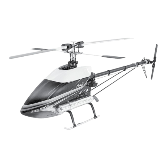
Kit introduction Thank you for purchasing the X-Cell Fury 55 by Miniature Aircraft USA. This model is the culmination of years of designing and manufacturing R/C helicopters. It is designed with the highest standards, and will provide years of enjoyment. Whether this is your first R/C model helicopter or you are an advanced R/C helicopter modeler, the X-Cell Fury 55 is a fantastic choice for a “50 size” model. r/c Helicopter safety A radio controlled model helicopter is not a toy, but rather a technically complex device that must be built and operated with care. It is also a fascinating and challenging part of the R/C sport, the mastery of which is very rewarding. A model helicopter must be built exactly in accordance with the building instructions. The kit manufacturer has spent much time and effort refining his product to make it reliable in operation and easy to build. The essentially bolt together construction can proceed quite rapidly, giving the builder a strong sense of accomplishment that encourages hasty progress from one construction phase to the next, so that the completed model can be more quickly seen and enjoyed. It is essential to recognize and guard against this tendency. -
Page 5: Academy Of Model Aeronautics (Ama)
Academy of model Aeronautics Miniature Aircraft USA highly recommends joining the Academy of Model Aeronautics (AMA). • AMA is the Academy of Model Aeronautics. • A MA is the world’s largest model aviation association, representing a membership of more than 150,000 from every walk of life, income level and age group. • AMA is a self-supporting, non-profit organization whose purpose is to promote development of model aviation as a recognized sport and worthwhile recreation activity. • AMA is an organization open to anyone interested in model aviation. • AMA is the official national body for model aviation in the United States. AMA sanctions more than a thousand model competitions throughout the country each year, and certifies official model flying records on a national and international level. -
Page 6: Kit Assembly
Kit Assembly Your Fury 55 kit will require a number of different supplies and tools to ensure the best final result. They are as follows: required lubricants and compounds: 1. Medium Strength Thread Locking Compound - X-Cell Super Lock Blue (MA3200-20) 2. Tri-Flow Oil (MA3200-02) 3. Tri-Flow Synthetic Grease (MA3200-06) 4. Medium Cyanoacrylate (CA) 5. Retaining Compound - X-Cell Super Lock Green (MA3200-22) required tools: 1. m4 Nut Driver 2. m5 Nut Driver 3. m5.5 Nut Driver... -
Page 7: Assembly Tips
important Assembly tips - PleAse reAd • F ollow the instructions. The methods of construction documented in this manual have been proven to work. Do not rush the build of your model! You have purchased a world class model helicopter kit, take your time and realize that the final result is now up to you. Take the time to fully understand each step, if you are unsure please contact Miniature Aircraft USA. • F ollow the order of assembly. The instructions have been organized into major sections and have been written in such a way that each step builds upon the work done in the previous step. Changing the order of assembly may result in unnecessary steps. • C lean all metal parts: All of the steel parts in this kit are coated with a lubricant to prevent them from rusting. This coating can interfere with the adhesives and thread locks needed for assembly. Use a solvent such as alcohol or acetone to clean the various metal parts, especially threads. -
Page 8: Kit Contents
Kit contents Please take some time to familiarize yourself with the contents of the kit. The Fury 55 kit has been broken down into six “bags”. Each bag contains parts and hardware. The hardware for each bag will be used only for that bag. There will be no left over parts after each bag is assembled. Bag Part No. Part Description Bag Part No. Part Description 1-A 128-10 C/F Right Main Frame .062” 2-B 128-123 Fan Shroud Set 1-A 128-13 C/F Left Main Frame .062” 128-125 C/F Shroud Deflector .062” 1-A 128-16 G-10 Antirotation Guide .075” 2-B 128-128 1/2 x 3/8 x 1/16 Rubber O-Rings 1-A 128-17 C/F Left Servo Mount .125” 2-B 128-22 C/F Rear Fan Shroud Mount .062” 1 1-A 128-18 C/F Right Servo Mount .125”... - Page 9 Kit contents Bag Part No. Part Description Bag Part No. Part Description Qty 4-B 0133 Ball Link 5-Hardware 0015 m2 Hex Nut 4-B 0159 m3 x 7 x 3 Ball Bearing 5-Hardware 0038 M2.5 x 10 Phillips Bolt 4-B 0361 Control Ball 5-Hardware 0039-2 m2.5 x 16 Phillips Bolt 4-B 0445 Plastic T/R Bellcrank 5-Hardware 0051 m3 x 3 Socket set Screw 4-B 0446-4 .165” x .310” x .003” S/S Shim 5-Hardware 0067 m3 x 14 Socket bolt 4-B 0457 F4-10m Thrust Bearing 3 pc.
-
Page 10: Bag 1 Hardware
bag 1 Hardware bag 1 Parts Pre-Assembled from Factory 0183 0183 128-48 128-71 122-28 0208 128-55 128-48 128-71 128-49 128-40 128-55 128-70 Lower Main Shaft Upper Main Shaft Aluminum Bearing Block Bearing Block Idler Pulleys 128-49 Autorotation Hub... -
Page 11: Getting Started
Getting started bag 1 Locate bag 1, and the hardware for bag 1. Please take the time to identify the hardware for this bag. Please note that the use of medium thread locking compound is always required when a part is threaded into metal. 128-62 Apply a small amount of medium thread lock when threading into metal parts 128-61 0060-1 0060-1 128-10 Illustration 1a... - Page 12 0064-3 Apply a small amount of medium thread lock when threading into metal parts 0060-1 0060-1 128-90 128-34 128-57 128-90 128-58 128-58 Illustration 1c 128-90 AT THIS LoCATIon 128-58 Locate the MA128-34 radio plate, two MA128-57 aluminum tray mounts, four MA128-58 frame spacers, two MA128-90 tank plate threaded stud mounts, five MA0060-1 m3x6 socket bolts, and four MA0064-3 m3x6 button head socket bolts. Refer to Illustration 1c for this step. Attach the MA128-34 radio plate to the two MA128-57 aluminum tray mounts using four MA0064-3 m3x6 button head socket bolts then attach the radio tray to the right side frame using two MA0060-1 m3x6 socket bolts. Attach the MA128-58 frame spacers.
- Page 13 128-13 0060-1 Apply a small amount of medium thread lock when threading into metal parts 0060-1 128-88 128-62 128-61 0060-1 0060-1 Illustration 1e 128-65 Locate the MA128-13 left main side frame, two MA128-88 rubber fuel tank mounts, one MA128-65 aluminum landing gear mounting block, one MA128-61 rear canopy mount, one MA128-62 front canopy mount, and six MA0060-1 m3x6 socket bolts. Refer to Illustration 1e for this step. Using six MA0060-1 m3x6 socket bolts, attach these components as shown in the illustration. Note that the two rubber fuel tank mounts are mounted on the inside of the frame. 0060-1 0060-1 0061 0060-1 Illustration 1f 0061 0060-1 Locate eleven MA0060-1 m3x6 socket bolts, and five MA0061 m3x8 socket bolts. It is time to join the right side frame to the left side frame. Refer to Illustration 1f for this step. Thread in the MA 0060-1 m3x6 socket bolts into the upper bearing block and one MA0060- 1 m3x6 socket bolt and one MA0061 m3x8 socket bolt into the lower bearing block as show. Note that the bolts threading into the upper and lower bearing blocks should not have been fully tightened at this time, as they need to remain slightly loose to allow for the alignment.
- Page 14 Apply a small amount of Illustration 1g medium thread lock when threading into metal parts 0060-1 128-18 0060-1 0060-1 0586-16 0586-16 noTE: NOTE: THE CoRnER BLoCKS of BoTH THE CORNER BLOCKS OF BOTH SERvo MoUnTS ARE InSTALLED 128-17 SERVO MOUNTS ARE INSTALLED 0060-1 BEHInD THE MAIn fRAMES BEHIND THE MAIN FRAMES.
- Page 15 Apply a small amount of medium thread lock when threading into metal parts noTE THE oRIEnTATIon of DRIvE BELT In BETWEEn THE TWo PULLyS 128-47 128-47 128-46 Illustration 1i.2 Illustration 1i.1 Locate the MA128-47 tail rotor drive belt, and the MA128-46 tail rotor drive pulley. Refer to Illustrations 1i.1 and 1i.2 for this step. Insert the tail rotor drive belt through the boom clamps as shown in the illustrations. Note the orientation of the tail rotor drive belt in between the two tension pulleys. Place the tail rotor drive pulley on top of the lower bearing block, keeping correct orientation of the drive belt between the tension pulleys. 128-43 Illustration 1j 0019 0019 128-49 0059-1...
-
Page 16: Bag 1 Completed Assembly Diagram
Illustration 1k 0058-6 0058-5 noTE: Dog-PoInT SET SCREW IS InSTALLED InTo THE BoTToM HoLE of THE MAIn SHAfT Locate the MA0058-5 m5x8 dog-point set screw, and the MA0058-6 m5x5 socket set screw. Refer to Illustration 1k for this step. These will both be threaded into the MA128-46 tail rotor drive pulley. The MA0058-5 m5x8 dog-point set screw will thread into the pulley, and extend into the indention on the main shaft. The MA0058-6 m5x5 socket set screw will simply tighten against the main shaft. bag 1 completed Assembly... -
Page 17: Bag 2 Hardware
bag 2 Hardware bag 2 Parts Pre-Assembled from Factory 0283 0439 128-114 128-121 128-133 0208 128-111 105-70 105-70 128-112 0279 128-40 128-106 128-109 Clutch Drive Centrifugal Start Shaft Assembly Bearing Block Clutch 128-110 Clutch Bell Unit... - Page 18 bag 2 Locate bag 2, and the hardware for bag 2. Please take the time to identify the hardware for this bag. Apply a small amount of 128-118 medium thread lock when threading into metal parts 0057 128-120 0273 128-110 128-109 Illustration 2a Locate the MA128-118 hex start adaptor, MA128-120 clutch drive bearing block, MA128-110 clutch bell unit, MA128-109 start shaft assembly, MA0273 steel shim washer, and two MA0057 m4x4 set screws. Insert the MA128-109 start shaft assembly into the MA128-110 clutch bell unit. Refer to Illustration 2a for this step. Place the MA0273 steel shim washer onto the top of the start shaft. Insert the start shaft through the MA128-120 clutch drive bearing block, taking note of the orientation of the block. Insert the MA128-118 hex start adaptor onto the start shaft, and line up the flat spot with the threaded hole on the hex start adaptor. Thread the MA0057 m4x4 set screw into the hex start adaptor, taking care not to allow vertical play in the start shaft assembly.
- Page 19 0078-5 Apply a small amount of medium thread lock when 128-106 threading into metal parts Illustration 2c 0064-3 128-104 EngInE nUT 0007 128-102 0063 CRAnKSHAfT WASHER 0067 0062-2 0003 128-25 0597-4 128-82 128-83 0063 noTE: DIMPLE fACES DoWn foR o.S. EngInES Locate the “50 size” engine you intend to use, MA128-106 centrifugal clutch, MA128-104 aluminum fan, MA128-102 aluminum fan hub, MA128-25 fan shroud plate, two MA0597-4 brass spacers, MA128-82 motor mount base, two MA128-83 motor mounts, two MA0078-5 m4x10 socket bolts, four MA0064-3 m3x6 button head socket bolts, the MA0007 6mm washer, six MA0063 m3x10...
- Page 20 128-128 Illustration 2d.2 128-125 128-123 128-128 Illustration 2d.1 Illustration 2d.3 0029 Locate the MA128-123 fan shroud set, the MA128-125 shroud deflector, two MA128-128 rubber “o” rings, and four MA0029 m2x2x13 Phillips self tapping screws. Refer to Illustration 2d.1, 2d.2 and 2d.3 for this step. Bring the two sides of the MA128-123 fan shroud set together with the MA128-125 shroud deflector between them. If there is flashing on the MA128-123 fan shroud, it can be easily trimmed with a razor knife. Note the correct orientation of these parts in the illustration. Use the four MA0029 m2.2x13 self tapping Phillips screws to join the fan shroud set together. Stretch the two MA128-128 rubber “o” rings over the alignment tabs as shown.
- Page 21 Apply a small amount of medium thread lock when threading into metal parts 0060-1 fAn SHRoUD 0061 MoToR MoUnT 128-22 0061 0060-1 0060-1 0061 128-65 Illustration 2f 128-28 0060-1 0061 Locate the MA128-28 left front frame plate, the MA128-22 rear fan shroud mount, 128-65 landing gear mounting block, six MA0060-1 m3x6 socket bolts, and eight MA0061 m3x8 socket bolts. Refer to Illustration 2f for this step. Attach the engine assembly motor mount to the RIGHT side frame using three of the MA0061 m3x8 socket bolts. Use two MA0060-1 m3x6 socket bolts to attach the MA128-65 landing gear mounting block to the MA128-28 left front frame plate. Use one MA0061 m3x8 socket bolt, and one MA0060-1 m3x6 socket bolt to attach the MA128-22 rear fan shroud mount to the left main frame. Use four MA0061 m3x8 socket bolts, and two MA0060-1 m3x6 socket bolts to mount the MA128-28 left front frame plate to the left main frame as shown in the illustration.
- Page 22 Apply a small amount of medium thread lock when threading into metal parts 115-65 190MM Long To MUffLER 0011-4 0014 115-65 128-99 140MM Long To EngInE 128-96 115-65 84MM Long 128-94 128-92 Illustration 2g.1 128-88 0060-1 Illustration 2g.2 128-85 Locate the MA128-99 fuel tank, MA128-96 fuel clunk, MA128-94 fuel nipple, MA128-92 rubber fuel tank plug, MA0011-4 m5x15x0.8 washer, MA0014-F m5 fine thread hex nut, and the MA115-65 fuel line.
-
Page 23: Bag 2 Completed Assembly Diagram
Apply a small amount of medium thread lock when threading into metal parts 0058-1 128-66 0003 0067 127-54A 127-53 Illustration 2h Locate the MA127-53 plastic struts, two MA128-66 aluminum skids, four MA127-54 skid plugs, four MA0067 m3x14 socket bolts, four MA0003 m3 washers, and four MA0058-1 m4x6 socket set screw. Please refer to Illustration 2h for this step. Using four MA0067 m3x14 socket screws, and four MA0003 m3 washers, attach the plastic struts to the aluminum landing gear mounting blocks. Slide the two MA128-66 aluminum skids through the struts, and position them as desired. Thread the MA0058-1 m4x6 socket set screws into the strut, and gently tighten just enough to prevent the skid from moving in the strut. Place a small amount of CA (cyanoacrylate) on each of the MA127-54 skid plugs, and push them into the MA128-66 aluminum skids. bag 2 completed Assembly... - Page 24 bags 3–4 Hardware bags 3–4 Parts Pre-Assembled from Factory 0442 0225 0443 0012-2 128-146 0058-3 0159 0440 128-145 128-162 128-160 0159 0439 0437 0439 128-157 128-148 128-161 LEfT “SHoWn” 128-164 onLy onE SIDE SHoWn RIgHT 0435 Tail Rotor Idler Boom Support Tail Plate Assembly Assembly 128-159...
- Page 25 bags 3–4 Locate bag 3 & 4, and the hardware for bag 3 & 4. Please take the time to identify the hardware for this bag. Apply a small amount of medium thread lock when threading into metal parts 0060-1 MASKIng TAPE noTCH fRonT of TAILBooM AT ToP of 128-47 noTCH IS AT THE ToP TAILBooM Illustration 3-4b 128-140 Illustration 3-4a This step will require some parts from bag 3, and all the parts from bag 4. Refer to Illustration 3-4a and 3-4b for this step. Locate the MA128-140 aluminum tail boom, and one MA0060-1 m3x6 socket bolt. Recall that the tail belt is already installed in the completed frame assembly from step 2. The MA128-47 Tail Rotor drive belt must be inserted through the boom with a counter clockwise ¼ twist.
- Page 26 Apply a small amount of medium thread lock when threading into metal parts 0060-1 0056 128-156 128-157 128-161 0065 127-15 0053 127-16 128-167 128-158 noTE: 128-156 THIS EnD of TAIL SHAfT HAS onLy onE DIMPLE foR TAIL PULLEy 128-164 0060-1 0060-1 Illustration 3-4d Locate the MA128-161 left tail plate with bearing, MA127-15 13t T/R pulley, MA127-16 T/R output shaft, MA128-158 aluminum...
- Page 27 High-Strength Thread Lock Apply a small amount of medium thread lock when 0064-9 threading into metal parts 0016-1 0065 High-Strength 129-149-A Thread Lock 129-59 0064-9 0016-1 0016-1 0064-9 High-Strength Thread Lock 129-148 High-Strength Thread Lock 129-149-B 0016-1 0064-9 Illustration 3-4e Locate the two MA128-148 boom support assemblies, MA128-149A upper boom support clamp, and MA128-149B lower boom support clamp, MA128-59 front boom support spacer, two MA0065 m3x12 socket bolts, four MA0064-9 m4x10 button head socket bolts, and four MA0016-1 external serrated lock washers. Refer to Illustration 3-4e for this step. Install the MA128-148 boom support assemblies to the...
- Page 28 High-Strength Thread Lock 0001 0361 0049-3 122-65 120-39 0873-1 0457 0446-4 0021 LARgE I.D. Illustration 3-4g High-Strength SMALL I.D. Thread Lock Locate the MA122-65 steel T/R hub, two MA0873-1 plastic T/R blade mounts, two MA120-39 ball bearings, two MA0457 thrust bearings, two MA0446-4 steel shims, two MA0361 control balls, two MA0001 washers, two MA0049-3 m2x8 socket bolts, and two MA0021 m4 lock nuts. Refer to Illustration 3-4g for this step. Use an MA0049-3 m2x8 socket bolt and an MA0001 washer to mount the MA0361 control ball to each plastic blade mount. Note that on each blade mount there are two mounting points for the control ball. For this model, the hole closest to the flat side of the T/R blade mount is correct. Push an MA120-39 ball bearing into each of the inner pockets of the MA0873-1 plastic T/R blade mount. Before installing the thrust bearing, you will need to determine which of the outer races has the larger inside diameter (I.D.) The outer race with the larger inside diameter will go in first.
- Page 29 Illustration 3-4i 128-142 0133 Locate the MA128-142 T/R control rod, and two MA0133 ball links. Refer to Illustration 3-4i for this step. Thread one of the MA0133 ball links onto the MA128-142 T/R control rod. Slide the T/R control rod through all three of the T/R control rod guides. Make sure they are aligned so that there are no bends in the T/R control rod. Thread on the other MA0133 ball link. It is important to align the T/R control rod guides so that they are positioned approximately 152mm from the ball links. Simply position the center T/R control rod guide evenly between the two outer T/R control rod guides. bag 3–4 completed Assembly...
-
Page 30: Bag 5 Hardware
bag 5 Hardware... - Page 31 bag 5 Locate bag 5, and the hardware for bag 5. Please take the time to identify the hardware for this bag. 128-176 Apply a small amount of medium thread lock when 0869 threading into metal parts 0095 0447-1 0159 0597-2 0159 0109 0221 0221 0109 0051 0597-2 0219 0159 0159 0097 0095 0447-1 128-176 0869 0112 0109 Completed assembly 0112 Illustration 5b...
- Page 32 Apply a small amount of medium thread lock when 128-172 threading into metal parts oR 128-173 SEE noTATIon In WRITTEn TExT SERvo 128-172 0039-2 4=SERvo Illustration 5c Locate the MA128-172 G-10 servo retainers, the carbon fiber cyclic servo spacers, eight MA0039-2 m2.5x16 Phillips bolts, and two of the servos you have chosen for cyclic control of the swashplate. Please refer to Illustration 5c for this step. Miniature Aircraft USA realizes that there are many different brands and models of servos available, and many have slightly different servo arm heights. We have included the spacers required for proper alignment of the control rod for nearly any servo available. Using the MA0039-2 m2.5x16...
- Page 33 Apply a small amount of medium thread lock when threading into metal parts 0038 0133 1-0103 THREADED BALL 1-0015 2MM HEx nUT RUDDER SERvo Illustration 5e Locate an MA0103 m2x5 threaded ball, an MA0015 m2 hex nut, four MA0038 m2.5x10 Phillips bolts, and the servo you have chosen to control the tail rotor. Refer to Illustration 5e for this step. Mount the MA0103 m2x5 threaded ball into the servo horn 14-15mm from the center of the horn and use an MA0015 m2 hex nut to secure the threaded ball to the servo horn. Use four MA0038 m2.5x10 Phillips bolts to mount the tail rotor servo to the frame. PEM nuts are already installed in the frame for this purpose. noTE: MoDEL SHoWn fRoM UnDERSIDE 0038 THRoTTLE SERvo RECEIvER LoCATIon 0038 THRoTTLE SERvo...
- Page 34 Illustration 5g SWASHPLATE AnD WASHoUT ASSEMBLy noTE: SERvo WHEEL oR ARM MUST BE 19.0MM oR 20.0MM fRoM SPLInE To 0103 THREADED BALL 0337 0015 SERvo WHEEL CUT To SIzE 0103 128-36 SERvo ALIgnMEnT TooL Locate six MA0133 plastic ball links, three MA0337 threaded control rods, MA128-36 servo alignment tool, three MA0103 m2x5 threaded control balls, three MA0015 m2 hex nuts, the servo horns you have chosen for your cyclic servos, and the swashplate and washout assembly you built in the first step of this bag. It is important to “center” your servos before mounting the servo horn. A simple tool has been provided to help you center the right and left cyclic servo, and a small hole in the frame to sight the exact center of the threaded control ball for the elevator servo. Place the MA128-36 servo alignment tool onto the socket bolt heads located above the main gear as shown in the illustration. When the MA128-36 servo alignment tool simply snaps over the socket bolt heads,...
- Page 35 Illustration 5i noTE: ELEvAToR SERvo RoD IS CEnTER/vERTICAL To MAIn SHAfT WHEn PRoPER SERvo SPACERS ARE USED noTE: ALL ConTRoL RoDS ARE PARALLEL To MAIn SHAfT WHEn PRoPER SERvo SPACERS ARE USED. Illustration 5h Illustrations 5h and 5i show the control rods parallel to the main shaft. It is important that these control rods are parallel to the main shaft. This can be adjusted using the spacers provided and discussed and shown in illustration 5c and 5d. Also shown in Illustration 5h is the throttle linkage, it is important that the linkage for the throttle is 90 degrees from the linkage when the throttle is at 50%, or as indicated in the manual for the engine you are using. Illustration 5j SMALL PIECE of HooK AnD...
- Page 36 Illustration 5k Illustration 5k shows the location of the holes for the canopy mounting grommets. It is first suggested that a 3mm hole be drilled in the front dimples to test fit the canopy. You can then determine if the rear holes require adjusting placement before opening the hole to the final grommet size.
-
Page 37: Bag 6 Hardware
bag 6 Hardware bags 6 Parts Pre-Assembled from Factory 106-02 128-180 128-182 Head Block Assembly 122-28 106-02 128-196 0317 3-D Bell Mixer 0840-27 0078-3 Assembly 0319 128-188 130-062 0283 Main Blade grips 130-062 128-186 0078-3 0283 0059-0... - Page 38 bag 6 Locate bag 6, and the hardware for bag 6. Please take the time to identify the hardware for this bag. 0067 Apply a small amount of THREADED HOLE medium thread lock when 0064-3 threading into metal parts 128-195 Illustration 6a 0112 0133 128-189 0133 SnAPED 128-189 In PoSITIon 0337 128-180 THREADED HoLE 0133 0112 0064-3 128-192 Locate the MA128-180 head block assembly, MA128-195 head button, two MA128-192 flybar control arms, two MA128-189 flybar control bar, four MA0133 ball links, two MA0337 m2x30 threaded control rods, two MA0112 m3x9.5 threaded control balls, four MA0064-3 m3x6 button head socket bolts, and one MA0067 m3x14 socket bolt. Refer to Illustration 6a for this step. Thread the four MA0331 ball links onto the two MA0337 m3x30 threaded control rod. These control rods should be made so that 13.75mm of threaded control rod is visible between the ball...
- Page 39 Illustration 6c Locate two MA128-188 main blade grips w/0319 bearings, two MA128-196 3-D bell mixer assemblies, two MA0112 m3x9.5 threaded control balls, two MA0109 m3x8 threaded 128-188 control balls, and two MA0091 m3x16 Phillips bolts. Refer to Illustration 6c for this step. Thread the MA0112 m3x9.5 threaded control balls into the OUTER holes on the MA128-196 3-D bell mixers. Note there is an inner hole, for the Fury 55 application we do not recommend installing the MA0112 m3x9.5 threaded control ball in this location. Mounting the MA0112 m3x9.5 threaded control ball on the inner hole on the Fury 55 may result in the binding and/or failure of the MA0133-1 ball link. Thread the MA0109 0109 m3x8 threaded control balls into the opposite side of each MA128-196 3-D bell mixer. Slide the MA0091 m3x16 Phillips bolt through each bell mixer, and apply a small amount of medium CA (cyanoacrylate) to the threads of the 0112 bolt, then thread the bolt into the hole on the blade grip as shown. It is important to thread the MA0091 Phillips bolts 128-196 into the correct hole on the blade grip for proper rotor head geometry. 0091 0848-2 gRoovE foR 0848-2 0332 0331 0844-6 128-187 Illustration 6d USE BoTH WASHERS foR 3D fLyIng.
- Page 40 Apply a small amount of medium thread lock when threading into metal parts 0331 0319 0324 0840-12 InnER RACE 120-7 0086 0840-12 Illustration 6e LARgE I.D. 0840-12 SMALL I.D. Locate two MA0331 m8x14x0.5 shim washers, two MA0319 m8x16x5 ball bearings, two MA0324 m10.75x16x1 shim washers, two MA0840-12 thrust bearings, two MA120-7 m5x5.5 C/F washer, and the two MA0086 m5x12 flanged socket bolts from the previous step. Refer to Illustration 6e for this step. In this step, you will complete two main rotor grip assemblies. Prepare the MA0840-12 thrust bearing by applying grease (MA3200-06 synthetic grease) to the inside pocket of the inner ball race. Push the MA0319 m8x16x5 ball bearing into the blade grip, followed by the MA0324 m10.75x16x1 shim, then the MA0840-12 thrust bearing. NOTE: install the...
- Page 41 0133-1 0053-5 0133-1 0133-1 120-25 0133-1 Illustration 6g Locate the two MA120-25 m3x86 threaded control rod, two MA0053-5 m3x16 socket set screws (these will be used as a threaded control rod), and four MA0133-1 plastic grey ball links. Refer to Illustration 6g for this step. Use the MA120-25 m3x86 threaded control rods, and MA0331-1 plastic grey ball links to make two “Hiller” control rods. These control rods should be made so that 70mm of thread control rod is visible between the ball links. See page 44 for control rod lengths. Use the MA0053-5 m3x16 socket set screws, and MA0133-1 plastic grey ball links to make two “Bell” control rods. These control rods should be made so that 0.0mm of thread control rod is visible between the ball links. See page 44 for control rod lengths. Install the completed control linkages as shown in the illustration. 0082 3700-150 2 PER SIDE 0082 0021 3700-150 USED onLy foR 12MM BLADE RooTS 0021 MAIn BLADE Illustration 6h Locate two MA0082 m4x38 socket bolts, two MA0021 m4 locknuts, four MA3700-150 1mm main rotor blade mount spacers, and the rotor blades you intend to use for this model. Refer to Illustration 6h for this step. NOTE: The main rotor blade grips on the Fury 55 have a 14mm grip spacing. Some rotor blades have a 12mm root thickness. If this is the case with your rotor blades, please use the MA3700-150 1mm main rotor blade mount spacers above and below each rotor blade root. If your rotor blades have a 14mm root thickness, do not use the spacers. Install the MA0082 m4x38 socket bolt through the hole in the blade grip, and through the rotor blades, and attach the MA0021 m4 locknut on the bottom. Main rotor grip tightness should be so that the blades do not “fall under their own weight”, but can still be rotated in the mount with moderate force.
-
Page 42: Electronics Installation
electronics installation 1/2” HooK AnD LooP TAPE RECEIvER 3/4” HooK AnD LooP TAPE BATTERy ADHESIvE BACKED HooK AnD LooP TAPE UnDER BATTERy AD RECEIvER HooK AnD LooP TAPE gyRo gyRo TAPE... - Page 44 control rod lengths Bell Mixer to flybar Servo to Swashplate Washout to flybar “Throttle” Servo to Carburetor approximate length “Hiller” Swashplate to Bell Mixer...
-
Page 45: Basic Model/Radio Set Up
basic model/radio set up The X-Cell Fury 55 is an eCCPM model. This means that the servos that are connected to the swashplate move together to achieve the function requested from the transmitter input. The transmitter mixes the channels required to achieve the correct movement of the swashplate. The X-Cell Fury 55 uses a very simple “direct” servo to swashplate system that decreases the overall parts count and complexity of the model. The very first thing to do, is center the swashplate servos. Your kit includes a simple pointer tool designed to help you center your servos. Ideally, you rotate the servo horn until the servo is centered, eliminating the use of sub-trim. For the pitch, aileron, and elevator servos: In your radio • ATV (servo endpoints) should be at 100%. -
Page 46: Swashplate Eccpm Set Up
swashplate eccPm set up: Now that you’ve built your new Fury 55 helicopter, you have to make the servos work together. The Fury 55 is an eCCPM model, and requires a specific radio program for the servos that control the swashplate. eCCPM is a mix that is already programmed in your transmitter, you just have to fine tune it to your Fury 55 and here’s how: The very first thing you need to do is tell your radio that a 120 degree eCCPM mix must be used. -
Page 47: Pitch Curve Set Up
Pitch curve set up: It is important that you build your model to exactly the way described in this manual. Make sure all your linkage rods are exactly the length determined in the manual included with your helicopter kit. First, go to the pitch curve menu in your radio for Idle up 1, or Stunt mode 1. You’ll see numbers, a graph or both. There will generally be 5 points you can adjust. You’ll have to imagine the points (1,2,3,4,5) as representing points on the collective stick, where point 1 represents full bottom stick, and 5 represents full top stick. Obviously that makes point 3 center stick and that’s where we start. Ensure that point 3 on the pitch curve (center stick) to equal 50% of the swashplate’s up and down travel, meaning the in the middle of it’s available travel. So, turn on your transmitter, and receiver, flip the flight mode switch to idle-up 1 or Stunt mode, and scroll to the pitch curve menu. Now place the left stick in the center. Use a pitch gauge, (We recommend MA3000-06) ensure that there is 0 degrees pitch on both rotor blades and that the mixing arms, and washout arms are perpendicular to the mainshaft. If any of this is untrue, you’ll need to make it so, by adjusting slightly the length of the pushrods. Now that you’ve got 0 degrees at center stick, and point 3 on the pitch curve has a value of 50% (don’t deviate here!) We can adjust the pitch at full top and bottom collective stick positions. Generally we want to have the same amount of pitch on the bottom stick position as we do on the top stick position in idle up or stunt mode. That means positive 10 degrees on top stick, and negative 10... -
Page 48: Throttle Curve Set Up
throttle curve set up: Build the throttle linkage as shown previously. This linkage length may change but ideally, you’ll want the servo linkage 90 degrees to the servo horn. This ensures equal travel in both directions. Turn on your transmitter. Scroll to the “throttle curve” screen and notice that there are points, usually 5, and the all have an assignable percentage. For example point 1 is 0% and point 5 is 100% (of the servo’s travel). Ensure that when the throttle/collective stick is at the mid point (point 3) that the engine’s carburetor is exactly ½ or 50% open (or otherwise stated in the manual included with the engine). This is crucial to easy set up. You may have to loosen the throttle arm on the carburetor for this to happen. Place the throttle stick to ½ and see where the carburetor opens to. On most popular engines today there is a mark that shows the halfway point. If it is not quite ½ way open you can use sub trim to make it so, but you don’t want to use too much. Too much sub trim can make further set up more difficult. Move the throttle stick to full throttle . The servo should open the carb to full open. If it opens less you can increase the end point in your radio so that it opens a little further, and if the servo binds (keeps wanting to move but the throttle is fully open) you can decrease the endpoint, but ideally you want the endpoints as close to 100% and 100% as possible. If you are experiencing the need for more servo movement, try moving the ball link out one hole on the servo arm, and conversely if you need much less servo movement, you can move the ball link one hole in. Once you have this set up in normal mode you’ll have to start and fly the helicopter to determine whether you need more or less throttle, but from what we’ve found this is a good starting point. - Page 49 Fury 55 Kit Hardware MA0001 M2 Washer MA0058-1 M4 x 6 Socket Bolt MA0003 M3 Washer-large MA0058-3 M4 x 16 Socket Set Screw MA0007 6mm Washer MA0058-5 M5 x 8 Dog-point Socket Set Screw MA0011-4 M5 x 15 x 0.8 Washer MA0058-6 M5 x 5 Socket Set Screw MA0012-1 M2.5 PEM Nut MA0059-1 M2.5 x 6 Socket Bolt MA0012-2 M3 PEM Nut MA0060-1 M3 x 6 Socket Bolt MA0014F Fine Thread M5 Hex Nut MA0061 M3 x 8 Socket Bolt MA0015 M2 Hex Nut MA0062-2 M3 x 12 Tapered Socket Head Bolt MA0016-1 M4 External Serrated Lock Washer MA0063 M3 x 10 Socket Bolt MA0017 M3 Hex Nut MA0064-3 M3 x 6 Button Head Socket Bolt...
- Page 50 Fury 55 Kit Parts MA120-25 M3 x 86 Threaded Control Rod MA128-108 Start Shaft Sleeve MA120-39 M5 x 10 x 4 Ball Bearing MA128-109 Start Shaft Assembly MA120-99 Canopy Knob MA128-110 Clutch Bell Unit MA122-28 M3 x .080” Brass Spacer MA128-111 Clutch Bell MA122-65 Steel T/R Hub MA128-113 Pinion Gear MA127-15 13T T/R Pulley MA128-118 6mm Hex Starting Adaptor MA127-16 T/R Output Shaft MA128-120 Clutch Drive Bearing Block w/Bearings MA127-53 Plastic Strut MA128-121 M6 x 13 x 5 Ball Bearing MA127-54A Skid Plugs MA128-123 Fan Shroud Set MA128-10 C/F Right Main Frame MA128-125 C/F Shroud Deflector MA128-13 C/F Left Main Frame...
- Page 51 notes...
- Page 52 notes...
- Page 53 notes...
- Page 54 notes...
- Page 55 Warranty The warranty covers defects in material or workmanship or missing components to the original purchaser for 30 days from the date of purchase. Miniature Aircraft, USA will replace or repair, at our discretion, the defective or missing component. Defective components must be returned to us prior to replacement. Any part, which has been improperly installed, abused, crash damaged or altered by unauthorized agencies, is not covered. Under no circumstances will the buyer be entitled to consequential or incidental damages. The components used in this kit are made from special materials designed for special applications and design strengths. We recommend that all replacement parts be original parts manufactured by Miniature Aircraft, USA, to ensure proper and safe operation of your model. Any part used which was manufactured by any firm other than Miniature Aircraft USA, VOIDS all warranties of this product by Miniature Aircraft USA.
- Page 56 2885 Farley lane • billings, mt 59101, usA Phone: 1.406.245.4883 Website: http://www.miniatureaircraftusa.com email: minair@miniatureacraftusa.com...
Need help?
Do you have a question about the Fury 55 X-CELL and is the answer not in the manual?
Questions and answers