Table of Contents
Advertisement
Advertisement
Chapters
Table of Contents

Related Manuals for Soyer BMK-16i


Summary of Contents for Soyer BMK-16i
- Page 1 Operating Instructions BMK-16i Stud Welder...
- Page 2 BMK-16i...
-
Page 3: Operating Instructions
Stud Welder Serial number* BMK-16i stud welder _________________________ Please enter the serial number here to have it immediately available if you need service support. Type table for BMK-16i stud welder Order No. Code designation Note P01340 BMK-16i Standard device (3 x 400 volt power supply) - Page 4 BMK-16i...
- Page 5 BMK-16i Congratulations on purchasing the BMK-16i SOYER stud welder. You have made an excellent choice. Your BMK-16i SOYER stud welder was specially developed for the high-speed fastening of SOYER welding studs in compliance with DIN EN ISO 13 918 on metallic, weldable workpieces.
- Page 6 BMK-16i...
- Page 7 BMK-16i Heinz Soyer Bolzenschweißtechnik GmbH Inninger Straße 14 82237 Wörthsee EC Conformity Declaration in compliance with EC Directive on Machinery 89/392/EEC, appendix II A We herewith declare that the machine described in the following and the version available on the market correspond in its design and construction to the fundamental safety and health requirements stipulated by EC Directive on Machinery.
- Page 8 BMK-16i...
-
Page 9: Table Of Contents
2.3.1 Manual electric welding (electrode welding) ..............18 2.3.2 TIG welding........................19 View / Dimensions ....................... 20 Technical data......................21 Circuit diagram of BMK-16i..................22 2.6.1 Wiring diagram......................22 2.6.2 Wiring diagram of modules ..................22 BMK-16i interfaces....................... 23 2.7.1 CNC interface ...................... - Page 10 Maintenance ...................... 61 Important instructions....................61 Cleaning........................61 8.2.1 Detergents ........................61 Replacement of components ..................62 Spare parts list for BMK-16i................63 Spare parts for BMK-16i ....................63 Troubleshooting ....................64 10.1 Malfunctions......................... 65 Transport and storage..................68 Terms of warranty..................... 68...
- Page 11 BMK-16i List of standards and guidelines ..............69 Appendix A / Adjustment of short-cycle drawn arc welding guns Appendix A...
-
Page 12: General
BMK-16i 1 General The following should be principally observed... With this stud welder you have purchased a product which • is state-of-the-art technology • fully complies with the current safety requirements and • enables successful working. Before installing the stud welder, please observe the following: •... -
Page 13: Application
For this purpose, however, special stud holders and ceramic ferrules or gas shrouds are required. With the BMK-16i SOYER stud welder it is also possible to weld studs of other metallic materials than steel. It is, however, necessary to first carry out experimental welds and to inspect them. -
Page 14: Chapters Of Operating Instructions
BMK-16i 1.5.1 Chapters of operating instructions The operating instructions describe the start-up and operation of the BMK-16i stud welder under normal conditions. The present operating instructions of the BMK-16i stud welder comprise the following chapters in detail: • Chapter 1 General •... -
Page 15: Conduct In The Case Of Malfunctions
Contacts and service address If you have any questions regarding the operation of the stud welding system, retrofits or if you require service, please contact your responsible service office or the following address: Heinz Soyer Bolzenschweißtechnik GmbH Etterschlag Inninger Straße 14 D-82237 Wörthsee Tel.: +49 (0) 8153-885-0... -
Page 16: Description Of Stud Welder
Short-cycle drawn arc technology Illustration 1: Short-cycle drawn arc technology The BMK-16i SOYER stud welder runs according to the principle of short-cycle drawn arc stud welding. For detailed information, please refer to the following regulations: • DIN EN ISO 14555, "Arc welding of metallic materials“... -
Page 17: Stud Welding
Stud welding The PH-2L stud welding gun with control cable and shielding gas equipment is the standard gun to be connected to the BMK-16i stud welder. Optionally you may also connect the PH-3N, PH-3L and PK-0K stud welding guns. These operating instructions only refer to the BMK-16i stud welder. -
Page 18: Manual Electric Welding / Tig Welding
BMK-16i IMPORTANT INFORMATION Ensure ceramic ferrules are absolutely dry. Manual electric welding / TIG welding Instructions on application These operating instructions only describe the function "stud welding". Instructions on manual electric welding / TIG welding can be obtained from the respective manufacturers of the necessary accessories. -
Page 19: Tig Welding
BMK-16i CAUTION During electrode welding, the connecting socket "welding cable" and the connecting plug "earth cable" are always live. The open-circuit voltage has always a direct voltage of approx. 80 V! 2.3.2 TIG welding TIG welding allows simple welding works using a TIG welding torch (welding torch is not included in delivery). -
Page 20: View / Dimensions
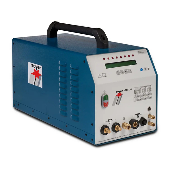
Illustration: Front view of BMK-16i Dimensions of BMK-16i 335 X 440 X 700 mm (w x h x d) -
Page 21: Technical Data
Designation BMK-16i Drawn arc stud welding (DS) Welding process Electrode welding rectifier SOYER threaded studs, DIN EN ISO 13918 from Welding range M3 – M16 RD (MR) or Ø 2 – 13mm Steel, stainless steel and heat-resistant steel (aluminium Material... -
Page 22: Circuit Diagram Of Bmk-16I
BMK-16i Circuit diagram of BMK-16i 2.6.1 Wiring diagram main switch DIL2 earth earth mains supply 400vac 50/60Hz 32AT socket A 12-pole 14-pole flat cable X3 PC-board SO112 grey grey mains filter 575V/6A yellow yellow X5/1 ON-pushbutton control transfo OFF-pushbutton 100mA... -
Page 23: Bmk-16I Interfaces
BMK-16i BMK-16i interfaces 2.7.1 CNC interface CNC interface Customer control 9-pole socket Start External release Start +U external +U external Terminology: Stud on workpiece Is only required when stud welder is operated via an external control. Start Contact releases the welding process. -
Page 24: Safety Instructions
BMK-16i 3 Safety instructions These operating instructions contain basic instructions which have to be complied with during installation and/or operation. It is therefore absolutely necessary that these operating instructions are read by the operator and responsible specialist staff prior to assembly and start-up. -
Page 25: Staff Qualification And Training
BMK-16i Staff qualification and training The staff responsible for operation, maintenance, inspection and assembly must have the respective qualification for carrying out these works. Field of responsibility, competence and the supervision of staff have to be exactly regulated by the user. If your personnel do not have the necessary knowledge, they have to be trained and instructed. -
Page 26: The Following Should Be Observed Before Starting The System
BMK-16i The following should be observed before starting the system… Before starting up the system, pay attention to the following information: • Juveniles under the age of 16 years must not operate the stud welding system. • Read all of the operating instructions before starting the system. -
Page 27: Working With The Stud Welding Equipment
BMK-16i Working with the stud welding equipment • Comply with all accident prevention regulations which apply to the operation of your stud welding device. One of the accident prevention regulations applicable to stud welders is VGB15 “Welding, cutting and similar working methods”. For more information, please contact the Employer’s Liability Insurance Association... -
Page 28: Stopping The Stud Welder
• Make sure stud welder can not be used by unauthorized persons. • Check welding cable and connections of the stud welder for damage such as burn-off, mechanical wear etc. and have damaged parts replaced by the SOYER customer service. -
Page 29: Installation Of Stud Welder
BMK-16i 4 Installation of stud welder The top of the BMK-16i stud welder is equipped with a carrying handle. CAUTION The carrying handle is intended for transport by hand only. Never pull ropes through this handle to lift the stud welder by means of a crane to the installation site. - Page 30 • Ensure sufficient ventilation of the working room when operating the welding system. NOTE The housing of BMK-16i stud welder corresponds to safety class IP 21. Please observe that this system of protection is not suitable for being operated or transported in the rain.
-
Page 31: Start-Up
BMK-16i 5 Start-up Front and rear view Front view of BMK-16i 1 OFF switch to switch the stud welder off 7 Air function "forward" (option) 2 Equipment-on indicator lamp 8 Air function "backward" (option) 3 ON switch to switch the stud welder on... -
Page 32: Operating Elements
Rear view of BMK-16i 15-pole connecting socket for controlling the feeder (BMK-16i automatic). 9-pole connecting socket for controlling the stud welder via a CNC interface or SPS control system (BMK-16i automatic) 9-pin connector, interface RS 232 (no function) Danger sign... -
Page 33: Display Elements
BMK-16i • Function keys for setting the welding parameters (item 6, chapter 5.1) The BMK-16i stud welder has four function keys on the front panel for setting the welding parameters: Function key “arrow up” Function key “arrow down” Function key “arrow left”... -
Page 34: Led Display (Item 4, Chapter 5.1)
BMK-16i 5.1.3 LED display (item 4, chapter 5.1) The first line of the display shows the designation of the parameters to be set. The second line shows the set value. When the parameter designation is flashing, you may change its value by using the keyboard. -
Page 35: Connecting Elements
BMK-16i 5.1.4 Connecting elements • Air function "forward" (item 7, chapter 5.1, option BMK-16i automatic) Connection for welding guns or heads with automatic stud feed. • Air function "backward" (item 8, chapter 5.1, option BMK-16i automatic) Connection for welding guns or heads with automatic stud feed. -
Page 36: Symbols
BMK-16i 5.1.5 Symbols Symbol Designation Function ON/OFF switch for switching the stud welder on Electrical energy and off. LED lights up when earth terminal of stud welder LED "Stud is connected and stud touches the workpiece. on Workpiece" LED lights up when pressing release switch of LED “Release"... -
Page 37: Preparation For Start-Up
BMK-16i Preparation for start-up Connect the stud welding gun and earth cables to the stud welder prior to start-up. 5.2.1 Earth connection • Attach earth cable to earth cable connectors (item 12, chapter 5.1) and lock by turning to the right until stop. -
Page 38: Connection Of Stud Welding Gun
BMK-16i Examples for various earth connections and possible effects: Balanced earth connection Ideal condition: The stud is located in the centre of both earth connections. Unbalanced earth connection Arc is deflected to the side where there is less current density. -
Page 39: Power Supply
BMK-16i 5.2.4 Power supply • Compare the power data (supply voltage / current consumption) on the type plate (item 17, chapter 5.1) with the data (supply voltage / fuse protection) of your power supply network. Always ensure the correct supply voltage in accordance with the data plate. - Page 40 BMK-16i 5.3.2.1 Operating mode "OP" (operational state) The operating mode "OP" allows normal welding operation with the welding parameters set. In the case of an excessive welding sequence, the welding operation is temporarily interrupted to avoid overheating of the stud welder.
- Page 41 BMK-16i • Check the lift setting of the stud welding gun and/or set the lift as described in the operating instructions of the welding gun or welding head. CAUTION Ensure once again that operating mode is set to "PRE" and observe the safety instructions in chapter 3.
- Page 42 BMK-16i signal is there. After a maximum of 4 sec, however, the lift test will be interrupted to protect the magnet. There is no welding current during this period of time. • If necessary, check and correct the height of lift according to the prescribed standard values (see table for welding parameters in chapter 6.1.2) for the welding gun or...
- Page 43 BMK-16i - the trigger of the welding gun or welding head - an active start signal at the CNC interface 5.3.2.5 Operating mode "Electrode welding" In the operating mode "Electrode welding" the stud welder works like a welding rectifier. CAUTION...
- Page 44 BMK-16i 5.3.2.6 Operating mode "TIG WELDING" In this operating mode the stud welder works as a TIG welding device. Gas and welding current flow when pressing the key on the burner. • Use the function key "arrow up" or "arrow down" (1 or 2) to set operating mode "TIG WELDING".
-
Page 45: Special Functions
BMK-16i Special functions With the stud welder BMK-16i you can call additional special functions: Start dealing with the special functions when you are familiar with the basic functions of the stud welder. The stud welder must be switched off when calling special functions. In order to call the respective special functions you have to press certain function key combinations and keep them pressed when starting the stud welder. -
Page 46: Special Function "Setting The Type Of Feeder And Its Functions
BMK-16i The operating counter can be reset to "0" by pressing the function key "arrow right". 5.4.3 Special function "Setting the type of feeder and its functions". With automatic operation, this special function serves to adapt the control to the feeder (parameter 1-4, only with BMK feeder). -
Page 47: Special Function "Selection Of Language. Display Of Software Version Number
BMK-16i Explanation of parameters • Plunger This parameter serves to adjust the after-blowing time of the stud feed blast air beyond the standard measure when the injection piston in the welding gun/welding head has moved forward to press the stud out of the stud holder. A longer time setting is required when welding e.g. -
Page 48: Special Function "Setting The Feeder Operation
BMK-16i 5.4.5 Special function "Setting the feeder operation" This special function serves as a help for setting the feeder operation when the stud welder is equipped with an optional automatic set. For calling this special function, please proceed as follows: •... -
Page 49: Operation
BMK-16i 6 Operation NOTE The applicable accident prevention and safety regulations in chapter 3 have to be complied with when operating the stud welder. 6.1.1 Setting welding parameters for standard welding operation • Switch ON/OFF switch to position “I” (item 3, chapter 5.1) The stud welder carries out a self test. - Page 50 BMK-16i The main current times for the most important stud dimensions are represented in tabular form in chapter 6.1.2 "Welding parameters for welding operation“. 6.1.1.3 PCT (preweld current time in milliseconds) • Select function "PCT" by pressing either function key "arrow left" (3) or "arrow right"...
- Page 51 BMK-16i 6.1.1.5 RLT (reload time in milliseconds) The reload time is the period of time the blast air valve requires for transporting the stud from the universal feeder to the welding gun or welding head. The longer the blast air hose is, the higher you have to set the reload time correspondingly. If automatic reload is not required, set value "0".
-
Page 52: Welding Parameters For Welding Operation
The welding parameters were determined with the BMK-16i stud welder and the PH-3N stud welding gun having a lift setting of about 2.5 mm. A steel plate with a thickness of 5 mm was used as base material for welding SOYER welding studs as per DIN EN ISO 13 918. -
Page 53: Welding Operation With Shielding Gas
BMK-16i Important information for standard welding operation (stud welding) The measures mentioned in the "Start-up of stud welder" chapter have already been performed. NOTE The applicable accident prevention and safety regulations indicated in chapter 3 must be complied with when operating the stud welder. -
Page 54: Preparation Of Gas Supply
BMK-16i 6.2.1 Preparation of gas supply Example for gas supply. Deviations are possible depending on the manufacturer 1 Gas cylinder 5 Shut-off valve (shielding gas as per chapter 2.1.1) 6 Gas supply hose 2 Hand wheel 7 Control cock for gas flow rate... -
Page 55: Instructions For Welding With Shielding Gas
BMK-16i 6.2.2 Instructions for welding with shielding gas • Set the parameters required for your welding task according to the table in chapter 6.1.2. 1 Foot plate 2 Gas shroud 3 Welding stud Ill. Stud welding with shielding gas Set gas flow rate to a value between 4 and 5 l/min. If the value is too high, the arc is extinguished, if the value is too low, the protective function of the gas is reduced. -
Page 56: Instructions For Welding With Ceramic Ferrules
BMK-16i Welding operation with ceramic ferrules is only possible when using SOYER drawn arc welding studs, types PD, MD, RD, UD and SD, similar to DIN EN ISO 13 918. 6.3.1 Instructions for welding with ceramic ferrules • Start the stud welder as described in chapter 5. -
Page 57: Quality Control (Stud Welding)
7 Quality control (stud welding) General Provided that the SOYER stud welding system is properly used and the materials are appropriately selected, the strength of the welding joint (welding zone) will always be stronger than that of the stud or base material. The following tests are carried out in general practice: •Visual inspection... -
Page 58: Test Execution
BMK-16i Test execution 7.3.1 Production of samples The dimensions of the test piece must be sufficient to carry out all tests. The thickness of the test piece must be the same as used in later production. Use the same welding positions and edge distances as on the component to be welded later. -
Page 59: Bend Test
BMK-16i 7.3.3 Bend test The bend test is a simple work test which serves to roughly check the setting values selected. The welding zone is subjected to undefined tension, pressure and bending. A minimum of 3 studs is welded and bent by means of a tube that is slipped over the stud. -
Page 60: Tensile Test
Note Numerous special accessories are available for perfectly testing stud welded joints. BP-1 SOYER Bend Testing Device for non-destructive stud testing to support quality assurance procedures DMS-1 SOYER Torque Wrench for non-destructive stud testing to support quality assurance procedures ZPV-1 SOYER Tensile Testing Device for non-destructive stud testing to support quality assurance procedures For further information, please contact our parent company or the customer service responsible for your area or visit our website at www.soyer.de. -
Page 61: Maintenance
Please note ® Only use original SOYER spare parts. Cleaning Cleaning should be carried out once a week depending on how soiled the stud welder Please pay particular attention to foreign substances in and around the air apertures in the housing. -
Page 62: Replacement Of Components
BMK-16i Replacement of components Defective components may only be replaced by trained SOYER servicemen. Perfect function of your stud welder can only be guaranteed when original SOYER spare parts are used. CAUTION Disconnect the mains cable from the mains supply and detach the shielding gas and compressed-air supplies before replacing any components. -
Page 63: Spare Parts List For Bmk-16I
BMK-16i 9 Spare parts list for BMK-16i Spare parts for BMK-16i In preparation Item No. Quantity Designation Order No. -
Page 64: Troubleshooting
The following list of errors, their causes and remedies is designed to help you eliminate any trouble immediately on the spot. If it is difficult or impossible to eliminate the trouble, please contact the SOYER customer service responsible for your area or Heinz Soyer Bolzenschweißtechnik GmbH. -
Page 65: Malfunctions
" Set gas flow rate to 4-5 l/min by means of the control cock. Solenoid valve in stud welder is soiled or defective. " Deaerate solenoid valve, clean it and/or have it replaced by SOYER customer service. Stud does not lift, neither Height of lift is not correctly set. - Page 66 Control of stud welder or welding gun is defective. (Stud does not lift, workpiece” lights up. even though height of lift is correctly set). " Contact SOYER customer service. Stud lifts, preweld current Operating mode (chapter 5.3.2.1) is set to position "PRE".
- Page 67 BMK-16i Welding gun in tilted position. " Ensure that all three gun legs are simultaneously and evenly positioned on the workpiece. Lift not correctly set. " Set lift correctly. Stud welder switches off. Stud lift not correctly set. " Set stud lift in accordance with the operating instructions of the welding gun.
-
Page 68: Transport And Storage
The stud welder is robustly designed and has a two-piece metal housing with front and rear panel. Owing to electronic components it should be ensured, however, that transport is free from vibrations. The BMK-16i stud welder has a carrying handle on its top for easy transport and mobile use within short distances. CAUTION The carrying handle is intended for transport by hand only. - Page 69 BMK-16i 13 List of standards and guidelines • 91/368/EEC EC Directive on Machinery (formerly 89/392 EEC) • 73/23/EEC EC Directive on Low-Voltage 89/336/EEC EC Directive on Electromagnetic Compatibility • DIN EN 292 – 1 Safety of machinery; basic terms, general principles of construction;...
- Page 70 Appendix A / Adjustment of drawn arc and short-cycle drawn arc stud welding guns Appendix A / Short-cycle drawn arc stud welding General............................2 Adjustment of stud welding gun ....................3 Stud holder for drawn arc operation..................3 Installation of stud holder into stud welding gun ..............4 Adjusting the depth of immersion...................
-
Page 71: General
The stud welding guns were equipped with different welding cable connectors depending on the welding range. Adapter cables (not included in delivery) enable you to operate the stud welding guns with SOYER stud welders having different welding cable connections. Order list for adapter cables / connectors... -
Page 72: Adjustment Of Stud Welding Gun
Appendix A / Adjustment of drawn arc and short-cycle drawn arc stud welding guns 2 Adjustment of stud welding gun Stud holder for drawn arc operation The PH-2L, PH-4L and PH-5L stud welding guns can be equipped with a stud holder for drawn arc operation when studs with a diameter of more than 6 mm are to be welded. -
Page 73: Installation Of Stud Holder Into Stud Welding Gun
Appendix A / Adjustment of short-cycle drawn arc stud welding guns Installation of stud holder into stud welding gun DANGER Switch off the welding equipment before adjusting it (mains switch must be in "OFF“ position). The stud holder suitable for the corresponding stud diameter is installed as follows: Ill. -
Page 74: Adjusting The Depth Of Immersion
Appendix A / Adjustment of drawn arc and short-cycle drawn arc stud welding guns Adjusting the depth of immersion DANGER Switch off stud welder to adjust the depth of immersion. The stud must be firmly inserted into the stud holder till it stops. The depth of immersion is the distance the stud projects over the end of the ceramic ferrule, the gas shroud or the support tube. - Page 75 Appendix A / Adjustment of short-cycle drawn arc stud welding guns How to adjust the depth of immersion: • Insert the relevant stud (3) into stud holder until stop • Loosen both Allen screws (item 2, chapter 2.2) • Move support legs (item 1, chapter 2.2) until the required depth of immersion is obtained •...
-
Page 76: Height Of Lift
Appendix A / Adjustment of drawn arc and short-cycle drawn arc stud welding guns Height of lift The height of lift is the distance the stud is lifted from the workpiece during the welding process. This distance is required for igniting the arc. Determination and adjustment of the lift is the same for welding with both support tube and ceramic ferrules. -
Page 77: Adjusting The Height Of Lift
Appendix A / Adjustment of short-cycle drawn arc stud welding guns 2.4.2 Adjusting the height of lift The height of lift can be adjusted by turning the adjusting cap (2) at the stud welder’s back to the left or to the right. Turning the adjusting cap (2) to the left increases the height of lift, turning to the right decreases the height of lift. -
Page 78: Immersion Speed
Appendix A / Adjustment of drawn arc and short-cycle drawn arc stud welding guns Immersion speed 2.5.1 Adjusting the speed of immersion for PH-4L and PH-5L The immersion speed or its damping depends on the stud diameter. Studs with a diameter up to 10 mm do not require any damping (turn adjusting screw (1) to the left till it stops). -
Page 79: Adjusting The Speed Of Immersion (Damping) For Ph-2L
Appendix A / Adjustment of short-cycle drawn arc stud welding guns 2.5.2 Adjusting the speed of immersion (damping) for PH-2L The PH-2L stud welding gun can only be set to “Damping ON” or “Damping OFF”. An infinite adjustment of the immersion speed is not possible. 1 Setting screw 2 Securing screw 3 Hexagon screwdriver 4mm... -
Page 80: Start-Up
Appendix A / Adjustment of drawn arc and short-cycle drawn arc stud welding guns 3 Start-up Total view The illustration below shows the standard stud welding gun for drawn arc operation. A large range of equipment is available. 1 Ceramic ferrule 2 Stud holder 3 Support retainer 4 Adjusting cap... -
Page 81: Operation
Appendix A / Adjustment of short-cycle drawn arc stud welding guns Operation • Connect stud welder to earth. • Adjust stud welding gun as described in Appendix A, chapter 1. • Connect stud welder to mains supply. • Adjust parameters at stud welder according to welding studs to be used. •... -
Page 82: Spare Parts / Wear Parts
Appendix A / Adjustment of drawn arc and short-cycle drawn arc stud welding guns 4 Spare parts / Wear parts Spare parts list for PH-2L, 4L, 5L stud holders and accessories View Description Dimensions / Type Order No. Drawn arc and short-cycle F01190 drawn arc stud holder F01191... - Page 83 Appendix A / Adjustment of short-cycle drawn arc stud welding guns View Description Dimensions / Type Order No. Flat-head screw M6 x 25 M01439 Two pieces are required for mounting the foot plate to the support legs Conical socket M8 Ø = 9.6mm M01440 Two pieces are required for mounting the foot plate to...
- Page 84 Appendix A / Adjustment of drawn arc and short-cycle drawn arc stud welding guns View Description Dimensions / Type Order No. Earth cable with clamp for 50mm² F01666/FA BMK-16i, LC, W and BMH- 16 SV Earth cable with clamp for 95mm² F01662/FA BMH22 SV C-clamp, large M01457...
-
Page 85: Spare Parts For Ph-2L
Appendix A / Adjustment of short-cycle drawn arc stud welding guns 5 Spare parts for PH-2L Spare parts list for PH-2L stud welding gun in preparation Appendix A /16... -
Page 86: Spare Parts For Ph-4L And Ph-5L
Appendix A / Adjustment of drawn arc and short-cycle drawn arc stud welding guns 6 Spare parts for PH-4L and PH-5L Spare parts list for PH-4L and PH-5L stud welding guns Item Qty. Designation Order No. Order No. PH-4L PH-5L PH-5L stud welding gun, complete P02250 P02260... - Page 87 Flat-head screw M4 x 12 M03634 Gun handle, left side F04184 Gun handle, right side F04185 Strain relief, part 2 F04186 Gun label, Soyer logo M03615 Bush for press button F04187 Cover disk for press button F04188 Press button, 1-pole E02103...
-
Page 88: Exploded View Of Ph-5L Stud Welding Gun
Appendix A / Adjustment of drawn arc and short-cycle drawn arc stud welding guns Exploded view of PH-5L stud welding gun Appendix A /19...
Need help?
Do you have a question about the BMK-16i and is the answer not in the manual?
Questions and answers