
Subscribe to Our Youtube Channel
Related Manuals for Soyer BMK-16i


Summary of Contents for Soyer BMK-16i
- Page 1 BMK-16i Operating Instructions Stud Welder GB: English Version Read these operating instructions before starting any work! Doc.ID: P00229 Date of issue: 12.2013 www.soyer.de...
- Page 3 Mains voltage 3 x 400 V P01341 BMK-16i Automatic Mains voltage 3 x 400 V Heinz Soyer Bolzenschweißtechnik GmbH www.soyer.de Inninger Straße 14 | 82237 Wörthsee | Tel.: +49 8153 8850 | Fax: +49 8153 8030 | E-mail: info@soyer.de |...
- Page 4 Thank you! Congratulations on purchasing the BMK-16i SOYER stud welder. You have made an excellent choice. Your BMK-16i SOYER stud welder was specially developed for the high-speed fastening of SOYER weld studs in compliance with DIN EN ISO 13918 on metallic, weldable workpieces.
- Page 5 Heinz Soyer Bolzenschweißtechnik GmbH Inninger Straße 14 82237 Wörthsee EC Conformity Declaration We herewith declare that the machine described in the following and the version available on the market correspond in design and construction to the fundamental safety and health requirements stipulated by EC Directive on Machinery.
-
Page 6: Table Of Contents
Drawn arc stud welding technology using shielding gas ..........15 3.2.2 Drawn arc stud welding technology using ceramic ferrules ..........15 Technical data ........................16 3.3.1 Wiring diagram BMK-16i ....................17 3.3.2 Wiring diagram - Components ..................17 Interfaces BMK-16i ....................... 18 3.4.1 CNC interface ........................ - Page 7 5.3.6 Electrode welding ......................32 5.3.7 TIG welding ........................33 Special functions – Submenus ..................... 33 5.4.1 Special function "Deleting the main memory" ..............33 5.4.2 Special functions – Extended submenu ................34 5.4.3 Special function "Display of operating counter" ............... 34 5.4.4 Special function "Setting the type of feeder and its functions"...
-
Page 8: Safety Instructions
1 Safety instructions These safety precautions are for your safety. General safety instructions Take part in a training programme. Read and follow all safety precautions listed below and all chapters of this manual before starting to weld. Non-compliance with the safety precautions can result in personal injuries or death. - Page 9 Fumes and gases can cause damage to your health Fumes and suspended/floating particles may be generated during welding. Beware of fumes detrimental to health, particularly when using surface treated materials. Please also observe the safety regulations applicable for your country. Do not inhale fumes and gases.
-
Page 10: Description Of Reference Signs In The Operating Instructions
Description of reference signs in the operating instructions The non-observance of safety instructions such as pictographs and warning words can cause damage to persons. The safety instructions of this operating manual describe the following: Safety instructions Danger! Immediate hazards which could result in serious personal injuries or loss of life. -
Page 11: Staff Qualification And Training
Roll up the cables without buckling them. • Prevent the stud welder being operated by unauthorized personnel. • Check welding cables and connections of the stud welder for damage such as burn-off, mechanical wear etc. and have damaged parts replaced by the SOYER customer service. -
Page 12: General
Only trained personnel may operate the stud welder. Intended use The BMK-16i SOYER stud welder allows you to weld pins and threaded studs from M3 – M16 or Ø 2 - 13 mm and many other types of weld fasteners manufactured from steel, stainless steel and aluminium. -
Page 13: Conduct In The Case Of Malfunctions
CAUTION Do not carry out any actions on the stud welding equipment without specifically knowing the operating instructions or the respective part. Ensure that only qualified and trained personnel familiar with the operating instructions operate the system. 2.4.2 Conduct in the case of malfunctions If malfunctions occur, first try to detect and eliminate the causes according to the list in the "Troubleshooting"... -
Page 14: Description Of Stud Welder
The PH-2L stud welding gun with control cable and shielding gas equipment is the standard gun to be connected to the BMK-16i stud welder. Optionally you may also connect the PH-3N, PK-0K and PH- 3N SRM stud welding guns. These operating instructions only refer to the BMK-16i stud welder. -
Page 15: Drawn Arc Stud Welding Technology Using Shielding Gas
The stud comes into contact The arc is guided through the The stud immerses into the very with the workpiece and is spiral-shaped magnetic field flat penetration zone and is raised. The arc is triggered. and completely melts both join inseparably connected. -
Page 16: Technical Data
BMK-16i Drawn arc stud welding (DA) Welding process Electrode welding rectifier SOYER threaded studs, DIN EN ISO 13918 from Welding range M3 - M16 RD (MR) or Ø 2 - 13 mm Steel, stainless steel and heat-resistant steel (aluminium Material... -
Page 17: Wiring Diagram Bmk-16I
3.3.1 Wiring diagram BMK-16i DIL2 Masse Masse 400Vac 50/60Hz 32AT Pistole 14Pol Flachkabel weiß 3,15AT 3,15AT X3 SO112 Gasventil F2 250mA Schleife braun 6pol Steuertrafo BV070301 braun 230V braun blau DIL2 70V Magnet Stecker A blau 12 pol S0 112 <O>... -
Page 18: Interfaces Bmk-16I
A complete device configuration for the central control via a PC is possible via the interface. Operation via the four function keys is therefore no longer necessary. 3.4.3 Feeder interface The feeder interface serves as the control and communication of our systems for the external stud feed e.g. by means of an UVR-300 SOYER universal feeder. -
Page 19: Pg.select
3.4.4 PG.Select Communication interface for the P3-Select/S gun distribution system. This interface serves for the automatic selection of programs (for further information, please refer to the operating instructions of the P3-Select gun distribution system). -
Page 20: Installation Of Stud Welding System
4 Installation of stud welding system The top of the BMK-16i stud welder is equipped with a carrying handle. CAUTION The carrying handle is intended for transport by hand only. Never pull ropes through this handle to lift the stud welder by means of a crane to the installation site. -
Page 21: Preparation Of Gas Supply
Preparation of gas supply Gas supply must be provided before welding with shielding gas. The gas connection at the rear side of the stud welder serves to supply the stud welder with gas by means of a pressure reducer (pressure reducing valve not included in delivery). The admissible gas flow value ranges from between 4 to 5 l/min. -
Page 22: Start-Up
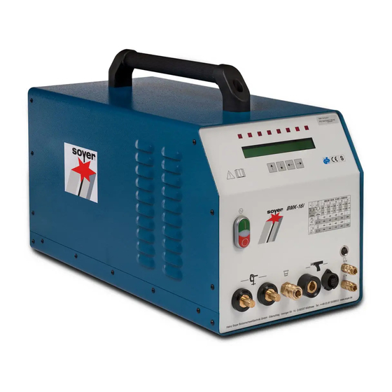
5 Start-up Front- and rear view Front view BMK-16i OFF switch (to switch stud welder off) Signal lamp (operating mode display) ON switch (to switch stud welder on) LCD display LED display for function control Function keys for setting the welding parameters Air function "forward"... - Page 23 Rear view BMK-16i 14* : 15-pole connecting socket for controlling the feeder 15* : 9-pole connecting socket for controlling the stud welder via a CNC interface 16* : 9-pin connector, interface RS 232 17 : Danger sign 18 : Type plate...
-
Page 24: Operating Elements
Press the "OFF" switch (item 1, chapter 5.1) to turn the stud welder off. Function keys for setting the welding parameters (item 6, chapter 5.1) The BMK-16i stud welder has four function keys on the front panel for setting the welding parameters: Function key “Arrow up”... -
Page 25: Display Elements (Led Displays)
5.1.2 Display elements (LED displays) Description 5.1 LED "SOW" LED lights up as soon as the stud touches the workpiece provided the workpiece is connected to the earth pole of the stud welder. 5.2 LED "Release" LED lights up when pressing the trigger switch of the gun or when the start signal at the external interface has been activated. - Page 26 Setting options for welding operation (OP) Parameter Description Range Number of programs available 1-30 Main current 100-1000 A (in increments of Main current time 3-1000 ms Preweld current time 0-999 ms Gas preflow time 0-9900 ms (in increments of Period of time during which the shielding gas valve 100) is open before welding.
-
Page 27: Description Of Symbols
5.1.4 Description of symbols Symbol Designation Function Electrical energy ON/OFF key to turn the stud welder on or off. LED "Stud on LED lights up when earth terminal of stud welder is Workpiece" connected and stud touches the workpiece. LED lights up when pressing release button of welding gun or LED "Release"... - Page 28 Ensure optimum contact with workpiece. Owing to the high welding current, an unbalanced current distribution may cause a magnetic blow effect on the arc, i.e. the arc for welding the stud is asymmetrical. This is shown by an irregular course of the welding bead on the side of the stud.
-
Page 29: Connection Of Stud Welding Gun
5.2.2 Connection of stud welding gun • Connect welding cable of welding gun to the relevant socket (item 10, chapter 5.1) and lock it by turning to the right until stop. • Insert control cable into control cable connection (item 9, chapter 5.1) and tighten with sleeve nut. -
Page 30: Operating Mode "Op
After the self test has been carried out successfully, the stud welder automatically sets the parameters which were last set. When the main switch is kept pressed, an input network check is carried out with those stud welder types equipped with a 3-phase protection module. In case of deviations from the admissible tolerance, the stud welder cannot be switched on. -
Page 31: Operating Mode "Lift" (Lift Test)
5.3.3 Operating mode "LIFT" (lift test) This operation mode enables you to adjust and check the lift of the gun or welding head. • Use the function key “Arrow up" or "Arrow down" to set operation mode "LIFT". • Insert a stud into the welding gun or welding head. •... -
Page 32: Operating Mode "Meas" (Measuring) Option
This operating mode checks whether the shielding gas flows through the gas shroud of the welding gun or welding head. As long as there is a triggering signal, shielding gas flows out of the gas shroud on the welding gun or welding head. This enables you to rinse the gas supply lines with shielding gas before starting to weld. -
Page 33: Tig Welding
Setting range: 40 -100 Special functions – Submenus With the stud welder BMK-16i you can call up additional special functions: The stud welder must be switched off when calling up special functions. In order to call up the respective special function you have to press certain function key combinations and keep them pressed when starting the stud welder. -
Page 34: Special Functions - Extended Submenu
5.4.2 Special functions – Extended submenu This submenu allows various parameters to be adapted. To call up this special function, the following steps are necessary: • Simultaneously press the “Down arrow”, “Up arrow” and “Left arrow” function keys and keep them pressed. -
Page 35: Special Function "Setting The Type Of Feeder And Its Functions
5.4.4 Special function "Setting the type of feeder and its functions" This special function serves to adapt the control to the feeder. To call up this special function, please proceed as follows: • Simultaneously press "Arrow right" and "Arrow left" keys and keep them pressed. •... -
Page 36: Special Function "Setting The Language
Explanation of parameters Parameter Description Range Default value Piston This parameter sets the after-running time of the stud 0 – 2000 ms feed blow air for the pushing piston in the welding gun/welding head to press the stud out of the stud chuck. -
Page 37: Special Function "Protocol/Log" (Option)
Serves to switch the measurement data transfer on or off via the RS 232 interface. The measurement data is transferred automatically after every weld. To further process the data, you need an external PC with the necessary Soyer software installed. -
Page 38: Welding Parameters
(see DVS guideline, Part 1, "Quality assurance of stud welding joints"). The welding parameters were determined with the BMK-16i stud welder and the PH-3N stud welding gun using a lift adjustment of about 2.5 mm. A steel plate with a thickness of 5 mm served as base metal for SOYER weld studs as per DIN EN ISO 13918. -
Page 39: Operation
6 Operation Brief description This section is designed to provide you with a quick start into the welding operation. For detailed information, please refer to chapter 6.2. NOTE The relevant accident prevention and safety regulations must be complied with when operating the stud welder. -
Page 40: Basic Setting Of The Srm Stud Chuck
Basic setting of the SRM stud chuck SRM stud chucks are available in the following different sizes: M8, Ø 9 mm, M10, Ø 10.8, M12 and M14. • The SRM stud chuck has been specifically designed for the PH-3N, PH-3N SRM, PH-9 and PH-9 SRM stud welding guns. -
Page 41: Basic Setting Of The Srm Nut Holder
The SRM nut holder has been specifically designed for the PH-3N SRM and PH-9 SRM stud welding guns. The SRM nut holder can be installed directly. Insert nut into nut holder. SOYER nut holders are already factory-set to SOYER weld nuts. No further adjustment is required. 1 Centering insert... - Page 42 Note for nut welding on punched sheet metal Use our weld nuts with centering inserts for punched sheet metal. Thanks to our centering insert, the weld nut is welded centrally over a hole. When using a template or other equipment, it is not necessary to use the centering insert.
-
Page 43: Start-Up Of Ph-3N Srm Stud Welding Gun
Start-up of PH-3N SRM stud welding gun NOTE: The PH-3N SRM welding gun is only suitable for stud sizes M6 - M12 and weld nut sizes M8, M10 and M12! TIP: The PH-3N SRM welding gun is provided with a standard gas shroud. Use inert gas in order to avoid the formation of pores and to optimise the collar formation. - Page 44 If necessary, prepare the ground connection (use protective goggles). The contact areas for the ground connection must be metallically bright. TIP: You can improve the transition resistances if both sides of the locking pliers have contact with the ground. NOTE: To facilitate the installation of the stud chuck or nut holder, move or dismantle the support together with the gas shroud.
- Page 45 How to correct the stud protrusion Insert the stud / weld nut into the chuck / nut holder and push it firmly until it comes to a stop. Use Allen wrench (size 3) to loosen the four Allen screws. Move support until a stud protrusion of approx. 1 – 1.5 mm is obtained.
- Page 46 Switch stud welder on by means of the mains switch. Please observe the safety instructions! Adjusting and checking the height of lift The height of lift is the distance by which the stud is lifted from the workpiece during the welding process. This distance is required for igniting the arc.
- Page 47 Position welding gun vertically on the workpiece (at a 90- degree angle to the workpiece). Check the selected parameters. Start the welding process by pressing the trigger. During the welding process, keep the gun steady. After completion of the welding process, remove gun vertically from the welded stud to prevent widening and damaging of the stud chuck.
-
Page 48: Notes On The "Lifting Test" Operation Mode
Notes on the "Lifting test" operation mode The lifting test allows for the activation of the gun’s lifting magnet thus controlling the setting. Proceed as follows: • Provide ground connection to the workpiece, connect welding gun. • Mount stud chuck to the welding gun and insert weld stud into stud chuck. •... -
Page 49: Srm Welding Operation
SRM welding operation Using this patented welding process (patent no.: 10 2004 051 389), threaded studs, pins, tapped studs etc. can be welded to metallic workpieces of alloyed and non-alloy steel. You need a stud welding gun or head, equipped with a special fixture for SRM stud welding. Due to the inert gas shroud with integrated magnetic coil, a magnetic field is generated. -
Page 50: Welding Operation With Ceramic Ferrules
• Press trigger switch. • When welding with shielding gas, the welding point is rinsed during the welding process as well as before and after welding for the period adjusted. • The LED "Gas valve open" indicates that the gas valve is open. •... -
Page 51: Welding Operation With Quality Control "Meas" (Option)
Only use original parts. No warranty is provided when non-Soyer welding studs are used. Press the trigger of the gun or welding head or give a triggering signal via the CNC interface. The stud is lifted off the workpiece and a test weld is carried out. - Page 52 Select the admissible deviation of the quality control Value TL = Tolerance 0 = Quality control off. 1 = smallest tolerance limit 50 = maximum tolerance limit In the operating mode "OP", the actual values of each weld are compared with the reference values previously determined.
-
Page 53: Quality Control (Stud Welding)
7 Quality control (stud welding) General instructions Provided the SOYER stud welding system is correctly used and the materials are appropriately selected, the strength of the welding joint (welding zone) will always be stronger than that of the stud or base material. -
Page 54: Bend Test
7.2.3 Bend test The bend test is a simple work test which serves to roughly check the setting values selected. The welding zone is subjected to undefined tension, pressure and bending. A minimum of 3 studs are welded and bent by means of a tube slipped over the stud. The test is successful when no superficial fissure or fracture is detected in the welding zone. -
Page 55: Maintenance
However, please observe the manufacturer’s specifications on the detergent you intend to use. Replacement of components Components may only be replaced by trained SOYER personnel. The perfect function of your stud welder can only be guaranteed when original SOYER spare parts are used. - Page 56 CAUTION Should it become necessary to replace fuses, only use fuses with the specified electrical values. Oversized fuses could either cause defects to the electrical system or a fire. DANGER Disconnect the mains plug from the mains supply when replacing fuses.
-
Page 57: Troubleshooting
The following list of errors, their causes and remedies is designed to help you eliminate any trouble immediately on the spot. If you cannot eliminate the trouble, please contact the SOYER customer service responsible for your area or Heinz Soyer Bolzenschweißtechnik GmbH. -
Page 58: Malfunctions
Set gas flow rate to 4-5 l/min by means of the regulating valve. Solenoid valve in stud welder is soiled or defective. Deaerate solenoid valve, clean it and/or have it replaced by SOYER customer service. Stud does not lift, Height of lift is not correctly set. - Page 59 You have used low-quality studs with inaccurate dimensions or poor surface finish. ® Only use SOYER welding studs as per DIN EN ISO 13 918. Welding time and/or gas flow incorrectly set. Readjust welding time and/or gas flow.
- Page 60 Stud welder switches Stud lift not correctly set. Set stud lift in accordance with the operating instructions of the welding off. gun. Switch stud welder on. You have pulled the welding gun off the workpiece while main current has been flowing.
-
Page 61: Transport And Storage
The stud welder is robustly designed and has a two-piece metal housing with front and rear panel. Owing to electronic components it should be ensured, however, that transport is free from vibrations. The BMK-16i stud welder has a carrying handle for easy transport and mobile use over short distances. -
Page 62: List Of Standards And Guidelines
12 List of standards and guidelines • 2006/42/EC EC Directive on Machinery • 2006/95/EC EC Directive on Low-Voltage • 2004/108/EC EC Directive on Electromagnetic Compatibility • DIN EN ISO 12100 – 1 Safety of machinery; basic terms, general principles of construction;... - Page 64 Heinz Soyer Bolzenschweißtechnik GmbH www.soyer.de Inninger Straße 14 | 82237 Wörthsee | Tel.: +49 8153 8850 | Fax: +49 8153 8030 | E-mail: info@soyer.de |...
Need help?
Do you have a question about the BMK-16i and is the answer not in the manual?
Questions and answers