Soyer PH-9 SRM12 Operating Manual
Stud welding device srm technology, stud welding gun
Hide thumbs
Also See for PH-9 SRM12:
- Operating manual (64 pages) ,
- Operating instructions manual (82 pages)

Related Manuals for Soyer PH-9 SRM12


Summary of Contents for Soyer PH-9 SRM12
- Page 1 Operating manual Stud welding device BMK-8i SRM technology Stud welding gun PH-9 SRM PH-9 SRM PH-3N SRM...
- Page 2 PH-9 SRM PH-9 SRM PH-3N SRM Operating manual Document no.: P00158, 01-2017, translation of the original manual (English: P00258) All information in this document is the property of Heinz Soyer Bolzenschweißtechnik GmbH. Revision status Document Created/modified Editor Date Original Prepared...
-
Page 3: Table Of Contents
6.2.1 Stud welding with SRM technology 6.2.2 Drawn arc stud welding technology with shielding gas 6.3. Overview of the controls 6.3.1 Display and setting area 6.4. Technical data of the BMK-8i stud welding device 6.5. Permitted stud welding guns Operating manual Soyer Bolzenschweißtechnik... - Page 4 12. Settings ............56 12.1. Setting the welding parameters 12.1.1 Help tables for device setting 12.1.2 Setting the welding current and the welding time 12.1.3 Setting/deactivating the SRM current Operating manual Soyer Bolzenschweißtechnik...
- Page 5 16. Warranty conditions ..........72 Operating manual Soyer Bolzenschweißtechnik...
-
Page 6: General Information
The following terms in this manual are marked with registered trademarks: SRM®: SRM stands for magnetic field stud welding and refers to welding or stud welding in a radially symmetrical magnetic field. SOYER®: Developments/technologies of Soyer GmbH. Operating manual Soyer Bolzenschweißtechnik... -
Page 7: Abbreviations And Definitions
HZ-1 threaded studs: SOYER universal studs with centring tip. MF threaded studs: SOYER threaded stud with a reduced flange diameter (MF stands for mini flange). 1.4 Declarations of conformity The devices are built according to the generally accepted codes of practice. - Page 8 General information Stud welding device Heinz Soyer Bolzenschweißtechnik GmbH Inninger Straße 14 82237 Wörthsee CE Declaration of Conformity We herewith declare that the machine described in the following and the version available on the market correspond in design and construction to the safety and health requirements of the listed guidelines and standards.
-
Page 9: Manufacturer
Web: www.soyer.de, www.soyer.com 1.6 Instruction, training Soyer offers optional and individual instruction in the operation of the devices. Soyer also offers training for customer-specific use of the devices. Information about the scope and costs of instruction and training can be obtained from Soyer GmbH. -
Page 10: Important Safety Instructions
Do not touch or open, danger for unauthorised per- sons. Danger for persons with a heart pacemaker or other medical implants. The info sign is not a safety alert. It indicates impor- tant and useful information on the subject. Operating manual Soyer Bolzenschweißtechnik... -
Page 11: General Safety Instructions
Starting the device with defective protection equipment is not allowed. • Repair or replace faulty protective equipment immediately. Unwanted operation by a third party must be prevented. Operating manual Soyer Bolzenschweißtechnik... - Page 12 • Work on electrical or electronic components must only be carried out by electrical specialists from Soyer Bolzenschweißtechnik. • Before working on the stud welding device, the mains switch of the device must be switched off and the mains plug of the stud welding device discon-nected.
- Page 13 Danger of burns from hot welding spatter Welding spatter or hot workpieces occurring due to the welding process can result in a danger of burns. • Do not store any inflammable and combustible materials in the welding area. Operating manual Soyer Bolzenschweißtechnik...
-
Page 14: Safety Instructions For The Working Method
If the gun is not put on properly or the gun settings are incorrect, a flash can occur during welding. Do not look directly into the flash. • The gun carries out lifting movements during the welding process. Do not hold the gun tight in the area of moving parts. Operating manual Soyer Bolzenschweißtechnik... -
Page 15: Personal Protection Equipment
Safety shoes Welding spatter occurs during welding. Wear suitable, non- combustible, heat-resistant safety shoes. Hearing protection Depending on the welding device and the welding applica- tion, relatively loud welding noise can occur. Wear suitable hearing protection. Operating manual Soyer Bolzenschweißtechnik... -
Page 16: Intended Use Of The Stud Welding Device
Pins and threaded studs from M3 to M12 and numerous different weld fasteners according to DIN EN ISO 13918, made of steel, stainless steel, aluminium and brass, can be welded with the SOYER stud welding guns described in this oper- ating manual. -
Page 17: Operating Company Prerequisites
The work must be carried out in line with the applicable technical rules for electrotechnical devices. cialists All devices of Soyer Bolzenschweißtechnik GmbH must only be opened by Soyer personnel or by personnel authorised by Soyer. Operating manual Soyer Bolzenschweißtechnik... -
Page 18: Transport
Local environmental guidelines for disposal must be complied with. Substances that are hazardous to water and the environment must be disposed of in accordance with legal regulations. Materials must be separated according to regulations where applicable. Operating manual Soyer Bolzenschweißtechnik... -
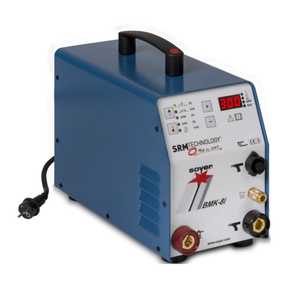
Page 19: Description Of The Bmk-8I Stud Welding Device
Pins and threaded studs from M3 - M8 (M6 and M8 preferred) made of steel and stainless steel can be welded using the SOYER BMK-8i stud welding device. Only welding studs from Soyer (HZ-1 and MF types) must be welded. -
Page 20: Stud Welding With Srm Technology
6.2.1 Stud welding with SRM technology The welding process recommended by Soyer for operating the BMK-8i is the pat- ented SRM welding process (patent no.: 10 2004 051 389) in conjunction with the also newly developed HZ-1 universal studs with flat front face and centring tip (patent no.: 10 2006 016 553). -
Page 21: Drawn Arc Stud Welding Technology With Shielding Gas
*) Corgon®18 is a gas mixture from Linde AG in D-82049 Höllriegelskreuth, Ger- many Further information on this subject can be found at www.soyer.com. Operating manual Soyer Bolzenschweißtechnik... -
Page 22: Overview Of The Controls
"6.3.1 Display and setting area" on page 24) Control cable connection of the gun Shielding gas connection of the gun, coupling socket KD 1/4 Welding cable connection of the gun Connection of the earth cable Operating manual Soyer Bolzenschweißtechnik... - Page 23 Description of the BMK-8i stud welding device Figure 2: Overview of the back of the device Item Designation Model plate Mains switch for switching the device on/off Mains connection cable Gas connection Carrying belt Operating manual Soyer Bolzenschweißtechnik...
-
Page 24: Display And Setting Area
Trigger button of the gun is pressed • Gun is placed on the workpiece and ready for welding • SRM is active • Gas preflow is active The LED next to the active operating state lights up. Operating manual Soyer Bolzenschweißtechnik... -
Page 25: Technical Data Of The Bmk-8I Stud Welding Device
Standard gun PH-9 SRM stud welding gun and PH-9 SRM Welding area SOYER threaded studs, from M3 - M8 (M6 and M8 preferred) HZ-1 and MF types or nails Ø 2 - 4 mm (optional) Current source Inverter technology Welding current... -
Page 26: Permitted Stud Welding Guns
Hazards for the operator can arise if the wrong welding gun is used. • Only use the welding guns from Soyer permitted in the following. The use of other guns or guns from another manufacturer will invalidate the declarations of conformity and the warranties of Soyer. -
Page 27: Cleaning The Stud Welding Device
Improper cleaning can lead to damage of the device. • Cleaning agents must not get into the device. • Do not use aggressive agents for cleaning. The frequency of cleaning depends on the conditions in which the stud welding device is used. Operating manual Soyer Bolzenschweißtechnik... -
Page 28: Description Of The Srm Stud Chuck
The standard stud chuck can hold studs up to a length of 60 mm. Different stud diameters require different stud chucks. When using studs with a length > 45 mm, the end stop screw must be shortened. Operating manual Soyer Bolzenschweißtechnik... - Page 29 Fix the end screw with the locknut. If the stud protrusion is more than 5 mm, the required trans- verse magnetic field is deflected sideways which can lead to uncontrolled SRM weld- ing. The setting is complete. Operating manual Soyer Bolzenschweißtechnik...
-
Page 30: Description Of The Ph-9 Srm Stud Welding Gun
To do so, observe chapter "12.1.5 Setting the lift time (height of lift) in "Setup" mode" on page 61. The height of lift is set using the adjusting wheel on the gun (see "Figure 4: PH-9 stud welding gun"). Operating manual Soyer Bolzenschweißtechnik... -
Page 31: Technical Data Of The Ph-9 Srm
SRM stud chuck Stud length Standard to 60 mm, special lengths possible on request and with special accessories Stud welding devices The gun is approved for operation on the following Soyer stud welding devices: • BMK-8i • BMK-12i • BMK-16i when using the adapter:... -
Page 32: Installing The Srm Stud Chuck In Ph-9 Srm 12
Step 6: Change the gas insert according to the required stud). Gas inserts: • Item no: M6 = F06738 • Item no: M8 = F06739 • Item no: M10 = F06740 • Item no: M12 = F06741 Operating manual Soyer Bolzenschweißtechnik... - Page 33 1 - 1.5 mm out of the shielding gas cap. If necessary, correct the setting of the stud chuck by shifting the tripod. 1 - 1.5 mm Step 11: Tighten the four socket head screws. Assembly is complete. Operating manual Soyer Bolzenschweißtechnik...
-
Page 34: Replacing The Srm 12 Support Tube Insert With Ph-9 Srm
Slide the new support ring up to the end stop in the mounting. When installing, make sure that the support tube insert and the mounting surface are clean. Step 4: Hand-tighten the two threaded pins on the tripod housing. Assembly is complete. Operating manual Soyer Bolzenschweißtechnik... -
Page 35: Cleaning The Stud Welding Gun
Danger of injury when cleaning Welding spatter and slag can have sharp edges. • Wear protective gloves when cleaning. To prevent impurities from welding spatter and slag and to simplify cleaning, we recommend using Soyer release spray (order number M01464). Operating manual Soyer Bolzenschweißtechnik... -
Page 36: Description Of The Ph-9 Srm +G Stud Welding Gun
SRM supply for connecting to the stud welding device Gas supply for connecting to the stud welding device +G support tube insert, with earth attachment Earth connection Button for the two-hand triggering (red point on the gun sticker) Operating manual Soyer Bolzenschweißtechnik... -
Page 37: Technical Data Of The Ph-9 Srm
Drawn arc stud welding (DA) • SRM welding process Stud diameter M3 - M12 (depending on the stud welding device) Stud chuck SRM stud chuck Stud length Standard to 60 mm, special lengths possible on request and with special accessories Operating manual Soyer Bolzenschweißtechnik... -
Page 38: Operation Of The Ph-9 Srm
Description of the PH-9 SRM +G stud welding gun Technical data of the PH-9 SRM +G stud welding gun Stud welding devices The gun is approved for operation on the following Soyer stud welding devices: • BMK-8i • BMK-12i •... -
Page 39: Welding With The Ph-9 Srm
Switch off the stud welding device if the gun is con- nected to the stud welding device. Step 2: Set the stud chuck to the required stud (see chapter "7.1 Setting the SRM stud chuck" on page 28). Step 3: Undo the union nut. Operating manual Soyer Bolzenschweißtechnik... - Page 40 Step 7: Slide the tripod with the shielding gas cap onto the gun. Step 8: Slide the stud chuck to the end stop in the spring piston in the gun. Step 9: Hand-tighten the union nut. Operating manual Soyer Bolzenschweißtechnik...
- Page 41 1 - 1.5 mm out of the shielding gas cap. If necessary, correct the setting of the stud chuck by shifting the 1 - 1.5 mm tripod. Step 11: Tighten the four socket head screws. Assembly is complete. Operating manual Soyer Bolzenschweißtechnik...
-
Page 42: Replacing The Srm Support Tube Insert With The Ph-9 Srm
Switch off the stud welding device if the gun is con- nected to the stud welding device. Step 2: Undo the earth connection socket head screw. Step 3: Undo the two threaded pins on the tripod housing. Step 4: Remove the old support tube insert. Operating manual Soyer Bolzenschweißtechnik... - Page 43 Step 7: Hand-tighten the two threaded pins on the tripod housing. Step 8: Tighten the earth connection socket head screw with a tightening torque of 250 - 300 cN. Assembly is complete. Operating manual Soyer Bolzenschweißtechnik...
-
Page 44: Cleaning The Stud Welding Gun
Danger of injury when cleaning Welding spatter and slag can have sharp edges. • Wear protective gloves when cleaning. To prevent impurities from welding spatter and slag and to simplify cleaning, we recommend using Soyer release spray (order number M01464). Operating manual Soyer Bolzenschweißtechnik... -
Page 45: Description Of The Ph-3N Srm Stud Welding Gun
The lift height can be determined using the lift time with the aid of the stud welding device. To do so, observe chapter "12.1.5 Setting the lift time (height of lift) in "Setup" mode" on page 61. The height of lift is set using the adjusting wheel on the gun. Operating manual Soyer Bolzenschweißtechnik... -
Page 46: Technical Data Of Ph-3N Srm Stud Welding Gun
SRM stud chuck and SRM nut holder Stud length Standard to 60 mm, special lengths possible on request and with special accessories Stud welding devices The gun is approved for operation on the following Soyer stud welding devices: • BMK-8i (*) • BMK-12i (*) •... -
Page 47: Installing The Srm Stud Chuck With Ph-3N Srm
Step 5: If there is still a stud chuck in the gun, remove it. Step 6: Slide the stud chuck to the end stop in the spring piston in the gun. Step 7: Hand-tighten the union nut. Operating manual Soyer Bolzenschweißtechnik... - Page 48 If necessary, correct the setting of the stud chuck by shifting the tripod. 1 - 1.5 mm Step 9: Fasten the tripod with the shielding gas cap onto the gun. Assembly is complete. Operating manual Soyer Bolzenschweißtechnik...
-
Page 49: Cleaning The Stud Welding Gun
Danger of injury when cleaning Welding spatter and slag can have sharp edges. • Wear protective gloves when cleaning. To prevent impurities from welding spatter and slag and to simplify cleaning, we recommend using Soyer release spray (order number M01464). Operating manual Soyer Bolzenschweißtechnik... -
Page 50: Setup And Connection
The stud welding device must only be operated in dry rooms. CAUTION CAUTION Danger from welding vapours Health threatening vapours can occur depending on the material of the work- piece and/or welding stud. • Where necessary, ensure suitable extraction of the welding vapours. Operating manual Soyer Bolzenschweißtechnik... -
Page 51: Connection Of The Stud Welding Device And The Stud Welding Guns
Then connect the earth cable to the workpiece (ensure a conductive connection). www.soyer.com Make sure the cable colour coding is correct when you establish the connection. Operating manual Soyer Bolzenschweißtechnik... -
Page 52: Connecting The Stud Welding Gun
The gas connection on the back of the device is used for supplying gas to the stud welding device via a pressure reducer (pressure reduction valve not included in the scope of delivery). The maximum permissible operating value for the shielding gas amount is 12 l/min. Operating manual Soyer Bolzenschweißtechnik... - Page 53 Gas flow rate meter [l/min] (pressure reduction valve) Shut-off valve for the gas connection hose of the stud welding device Gas connection hose of the stud welding device Valve for regulating the gas flow rate (maximum permissible gas amount: 12 l/min) Operating manual Soyer Bolzenschweißtechnik...
- Page 54 Use the regulating valve to set a shielding gas flow rate of approx. 4 - 5 l/min. Step 5: Plug the shield gas hose of the gun into the stud welding device. BMK-8i www.soyer.com The gas supply is established. Operating manual Soyer Bolzenschweißtechnik...
- Page 55 Carry out all necessary, prescribed checks of the gas cylinder, fittings and lines. • Safeguard the gas supply against unauthorised access. The following shielding gas mixtures are recommended: • 82% argon and 18% CO2 (preferred) • 90% argon and 10% CO2 • 85% argon and 15% CO2 Operating manual Soyer Bolzenschweißtechnik...
-
Page 56: Settings
Diameter of the welding stud 12.1.1 Help tables for device setting The values given in the following table can be useful as guide values for an initial sample weld. How the respective settings are made is explained in later chapters. Operating manual Soyer Bolzenschweißtechnik... - Page 57 0.30 0.30 0.50 Gas preflow time [s] Lift time/Height of lift Required height of lift, approx.: 1 - 1.5 mm Lift time, approx. [ms] 12.5 10.0 The values were determined using a 2 mm thick plate. Operating manual Soyer Bolzenschweißtechnik...
-
Page 58: Setting The Welding Current And The Welding Time
The LED lights up if the selec- [ms] > tion is correct. [ms] Step 5: Use the +/- keys to set the required value for the welding time on the display. The welding time has been set. Operating manual Soyer Bolzenschweißtechnik... -
Page 59: Setting/Deactivating The Srm Current
The SRM current is adjustable from 0 - 1500 mA (display in A) in 50 mA steps (0.05 A). If the setting is "0", SRM is deactivated. The SRM current has been set. Operating manual Soyer Bolzenschweißtechnik... -
Page 60: Setting The Gas Preflow Time
The LED lights up if the selec- [ms] > tion is correct. [ms] Step 3: Use the +/- keys to set the required value (1-5 s) for the gas preflow time on the dis- play. The gas preflow time has been set. Operating manual Soyer Bolzenschweißtechnik... -
Page 61: Setting The Lift Time (Height Of Lift) In "Setup" Mode
Step 2: Fit the gun with a welding stud. Step 3: Use the ↑↓ arrow keys to select the position for the lift test. The LED lights up if the selec- [ms] > tion is correct. [ms] Operating manual Soyer Bolzenschweißtechnik... - Page 62 (green LEDs). Notes on "Setup" mode • The setup process can be repeated as often as required. However, to avoid the magnetic coil overheating, maintain a waiting time of approx. one second between test strokes. Operating manual Soyer Bolzenschweißtechnik...
- Page 63 The lift can only be tested when the gun is po- sitioned flush on the workpiece. • Two-hand operation must be activated to trig- ger the gun. All three trigger buttons have to be pressed to do this. Operating manual Soyer Bolzenschweißtechnik...
-
Page 64: Welding Operation
Step 3: Insert the matching stud chuck and a welding stud (see chapter "7. Description of the SRM stud chuck" on page 28). Only use Soyer welding studs. Step 4: Check the welding parameters (see chapter "12. Settings" on page 56). - Page 65 This prevents the stud chuck widening and becom- ing damaged. For welding with the PH-9 SRM +G gun please consult chapter "9.2 Operation of the PH-9 SRM +G" on page 38. The welding process is now complete. Operating manual Soyer Bolzenschweißtechnik...
-
Page 66: Notes On Checking The Quality Of The Weld
Welding operation 13.2 Notes on checking the quality of the weld If the SOYER stud welding system is used properly and the correct materials are chosen, the strength of the weld joint (weld zone) is always higher than that of the stud or the basic material. -
Page 67: Switching Off The Device
Switch off the stud welding device at the mains switch. This also automatically switches off the connected welding gun. Make sure that the stud welding device cannot be switched on and used by un- authorised persons. Close the shut-off valves to the gas supply. Operating manual Soyer Bolzenschweißtechnik... -
Page 68: Weld Defects And Their Causes
13.4 Weld defects and their causes The most common weld defects, their possible causes and how to troubleshoot them are described in the following. If the fault cannot be remedied as described, please contact Heinz Soyer Bolzen- schweißtechnik GmbH. Faults... - Page 69 The controller of the device or the welding gun is defective. (The stud does not lift despite correctly set height of lift). • Notify SOYER Customer Service. The stud lifts but the The lift is too large. main current is not •...
- Page 70 Low quality studs with imprecise dimensions or poor surface quality have been used. • Only use Soyer welding studs. The welding time and/or the gas flow rate are/is not set correctly. • Set the welding time and/or the gas flow rate again.
- Page 71 Grind off the surface. Faulty mains supply. • Check the mains supply fuses. Fuse in the device defective. • Notify Customer Service. Stud thread is burned. The stud chuck is worn out. • Replace the stud chuck. Operating manual Soyer Bolzenschweißtechnik...
-
Page 72: Maintenance And Repair
Maintenance and repair 14. Maintenance and repair The stud welding device and the stud welding guns must only be maintained and repaired by Heinz Soyer Schweißtechnik GmbH or its authorised specialists. 15. Service In the event of service, please contact: Heinz Soyer Bolzenschweißtechnik GmbH... - Page 73 Warranty conditions Operating manual Soyer Bolzenschweißtechnik...
- Page 74 Heinz Soyer Bolzenschweißtechnik GmbH Inninger Straße 14 82237 Wörthsee Tel.: 0049-8153-885-0 Mail: info@soyer.de www.soyer.com www.srm-technology.com...
Need help?
Do you have a question about the PH-9 SRM12 and is the answer not in the manual?
Questions and answers