Table of Contents
Advertisement
Quick Links
Advertisement
Chapters
Table of Contents

Related Manuals for Soyer BMK-8 U


Summary of Contents for Soyer BMK-8 U
- Page 1 Operating Instructions BMK-8 U BMK-12 W Stud Welders...
- Page 2 BMK-8 U / BMK-12 W...
- Page 3 BMK-8 U / BMK-12 W Operating Instructions BMK-8 U BMK-12 W Stud Welders Serial number* Stud welder BMK- _________________________ Please enter your type of stud welder and serial number here, so that these data are immediately available if you need service support Survey of stud welder types Order no.
- Page 4 Congratulations on purchasing a SOYER stud welder. You have made an excellent choice. Your SOYER stud welder was specially developed for the high-speed fastening of SOYER welding studs in compliance with DIN EN ISO 13 918 on metallic workpieces. Our devices have been tested with regard to safety requirements and corres- pond to the currently valid European and national guidelines.
- Page 5 BMK-8 U / BMK-12 W Heinz Soyer Bolzenschweißtechnik GmbH Inninger Straße 14 82237 Wörthsee CE Declaration of Conformity We herewith declare that the machine described in the following and the version available on the market correspond in design and construction to the safety and health requirements of the listed guidelines and standards.
-
Page 6: Table Of Contents
BMK-8 U / BMK-12 W Table of contents Safety precautions ....................8 Description of reference signs in the operating instructions ........10 Staff qualification and training ..................11 Dangers in the case of non-compliance with safety instructions ......... 11 Before starting to weld....................11 Working with the stud welding equipment .............. - Page 7 BMK-8 U / BMK-12 W Operation ......................34 Standard operation ...................... 34 6.1.1 Setting welding parameters for standard welding operation........34 Welding parameters for welding operation ..............36 6.2.1 Minimum sheet thickness when welding with drawn arc operation ......36 Important information for standard welding operation (stud welding) ......
-
Page 8: Safety Precautions
BMK-8 U / BMK-12 W 1 Safety precautions These safety precautions are for your safety. General safety instructions Become trained and read and follow all safety precautions listed below as well as all chapters of this manual before starting to weld. - Page 9 BMK-8 U / BMK-12 W Fumes and gases can cause damage to your health Fumes and suspended matters may be generated during welding. Beware of fumes detrimental to health, particularly when using surface treated materials. If possible, only weld in rooms which are higher that 3 m. Please also observe the safety regulations applicable for your country.
-
Page 10: Description Of Reference Signs In The Operating Instructions
BMK-8 U / BMK-12 W Description of reference signs in the operating instructions The non-observance of safety instructions such as pictographs and warning words can cause damage to persons. The safety instructions of this manual describe the following: Safety instructions... -
Page 11: Staff Qualification And Training
BMK-8 U / BMK-12 W Staff qualification and training The staff responsible for operation, maintenance, inspection and assembly must have the respective qualification for carrying out these works. Field of responsibility, competence and the supervision of staff have to be exactly regulated by the user. If your personnel do not have the necessary knowledge, they have to be trained and instructed. -
Page 12: General
For this purpose, however, special stud holders and ceramic ferrules or gas shrouds are required. With the BMK-8 U / BMK-12 W SOYER stud welders it is also possible to weld studs of other metallic materials than steel. It is, however, necessary to first carry out experimental welds and to inspect them. -
Page 13: Information On The Documentation
BMK-8 U / BMK-12 W Information on the documentation The following operating instructions are supplied with the BMK-8 U / BMK-12 W stud welders: • Operating instructions for BMK-8 U / BMK-12 W Order no. P00220 2.4.1 Information on operating instructions... -
Page 14: Description Of Stud Welder
Short-cycle drawn arc stud welding technology Illustration 1: Short-cycle drawn arc stud welding technology The BMK-8 U / BMK-12 W SOYER stud welders run according to the principle of short-cycle drawn arc stud welding. A d.c. power supply provides the welding current. For detailed information, please refer to the following regulations: •... -
Page 15: Stud Welding
BMK-8 U / BMK-12 W The following welding methods are possible when using the BMK-8U / BMK-12W SOYER stud welders: • Short-cycle drawn arc stud welding without shielding gas and ceramic ferrules. • Drawn arc stud welding using ceramic ferrules as auxiliary aid. -
Page 16: Technical Data
BMK-8 U / BMK-12 W Technical data Designation BMK 8 U BMK 12 W Welding process Short-cycle drawn arc stud welding Welding range for SOYER M3 – RD 10 or. 2 – 9 mm M3 – RD 12 or. 2 – 11 mm... -
Page 17: Bmk-12 W Interfaces
BMK-8 U / BMK-12 W BMK-12 W interfaces 3.5.1 CNC interface CNC-interface Customer control 9-pole D-Sub socket terminal strip Start Release Start +U external +U external Terminology: Stud on workpiece Shows contact between stud and workpiece. Contact is necessary to start welding process via the starting signal. -
Page 18: Installation Of Stud Welder
BMK-8 U / BMK-12 W 4 Installation of stud welder The top of the BMK-8U / BMK-12 W stud welders is equipped with two plastic carrying handles. CAUTION These handles are intended for transport by hand only. Never pull ropes through these handles to lift the stud welder by means of a crane to the installation site. -
Page 19: Start-Up
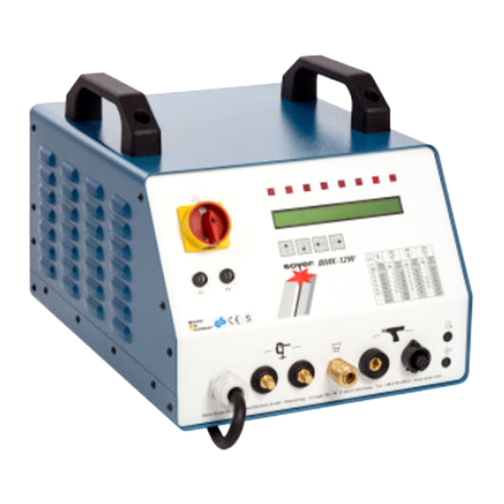
BMK-8 U / BMK-12 W 5 Start-up Front and rear view Front view of BMK-8U / BMK-12 W (above illustration of BMK-12W corresponds to BMK-8U) • Fuse element F1 • Main switch (switch stud welder on) •Fuse element F2 • LCD display •... - Page 20 BMK-8 U / BMK-12 W 20/21 Rear view of BMK-8U / BMK-12 W 15-pole connecting socket / feeder interface (OPTION) The feeder interface serves to connect the feeder control to the stud welding device. 9-pole connecting socket / CNC interface (OPTION) The CNC interface serves to be connected with an external control system to control the stud welding process.
-
Page 21: Operating Elements
BMK-8 U / BMK-12 W 5.1.1 Operating elements • Main switch Use the main switch to turn the stud welder on and off. • Function keys for setting the welding parameters The BMK-8U / BMK-12 W stud welders have 4 function keys on the front panel for setting the welding parameters: Function key “arrow up”... -
Page 22: Lcd Display
BMK-8 U / BMK-12 W When switching the equipment on, the 8 LEDs light up for a short period to check proper operation. If not all LEDs light up when starting the system, please contact your service partner. • LCD display 5.1.3... -
Page 23: Symbols
BMK-8 U / BMK-12 W 5.1.4 Symbols Symbol Designation Function Electrical energy Main switch for switching stud welder on and off. LED lights up when earth terminal of stud welder LED "Stud is connected and stud touches the workpiece. on Workpiece"... -
Page 24: Fuses (Items 1 And 3, Chapter 5.1)
BMK-8 U / BMK-12 W 5.1.5 Fuses (items 1 and 3, chapter 5.1) The BMK-8U / BMK-12 W stud welders are protected by the following fuses: - Fuse F1 0.315 A slow-blow - Fuse F2 2 A slow-blow (with 400V up to 500V) or 3.15 AT with 230V... -
Page 25: Connection Of Stud Welding Gun
BMK-8 U / BMK-12 W Examples for various earth connections and possible effects: Balanced earth connection Ideal condition: The stud is located in the centre of both earth connections Unbalanced earth connection Arc is deflected to the side where there is less current density... -
Page 26: Adjustment Of Operation Modes
BMK-8 U / BMK-12 W Adjustment of operation modes 5.2.1 Starting the stud welder After switching the stud welder on, the 8 LED lamps (items 5.1 - 5.8, chapter 5.1.2) light up for a short period. The stud welder carries out a self test which is shown on the LCD display (item 4, chapter 5.1). - Page 27 BMK-8 U / BMK-12 W CAUTION Protective goggles are required to carry out this test. Please also refer to the safety instructions. • Use the function key "arrow up" or "arrow down" (1 or 2) to set operation mode "PRE".
- Page 28 BMK-8 U / BMK-12 W • Press the trigger of the gun or the welding head or give a triggering signal via the CNC interface. The stud is lifted off the workpiece as long as the triggering signal is there. After a maximum of 4 seconds, however, the lift test will be interrupted to protect the magnet.
-
Page 29: Special Functions
BMK-8 U / BMK-12 W Special functions With the BMK-8U / BMK-12 W stud welders you can call additional special functions: Start dealing with the special functions when you are familiar with the basic functions of the stud welder. -
Page 30: Special Function "Setting The Type Of Feeder And Its Functions
BMK-8 U / BMK-12 W • The operating counter can be reset to "0" by pressing the function key "arrow right". 5.3.3 Special function "Setting the type of feeder and its functions" With automatic operation, these special functions serve to adapt the control to the feeder (parameter 1-4, only with BMK feeder). -
Page 31: Special Function "Selection Of Language. Display Of Software Version Number
BMK-8 U / BMK-12 W Explanation of parameters • Piston This parameter serves to adjust the post-blow time of the stud feed blow air beyond the standard measure when the pushing piston in the welding gun/welding head has moved forward to press the stud out of the stud holder. -
Page 32: Special Function "Setting The Feeder Operation
BMK-8 U / BMK-12 W 5.3.5 Special function "Setting the feeder operation" This special function serves as a help for setting the feeder operation when the stud welder is equipped with an optional automatic set. For calling this special function, please proceed as follows: •... -
Page 33: Extended Special Functions
These special functions are set by our customer service, if required. Do not alter any parameters without specifically knowing the procedure. Should you require any further information, please contact the SOYER customer service responsible for your area or Heinz Soyer Bolzenschweißtechnik GmbH. -
Page 34: Operation
BMK-8 U / BMK-12 W 6 Operation Standard operation The measures mentioned in the "Start-up of stud welder" chapter have already been performed. 6.1.1 Setting welding parameters for standard welding operation NOTE The applicable accident prevention and safety regulations have to be complied with when operating the stud welder. - Page 35 BMK-8 U / BMK-12 W 6.1.1.3 GPTIME (Gas preflow time) The gas preflow time is the period of time, during which the shielding gas valve is open before starting the welding process and remains open after the welding process has been completed. Set value "0"...
-
Page 36: Welding Parameters For Welding Operation
The values indicated in the tables are standard values which are exclusively valid for studs supplied by SOYER. They may vary depending on the type of workpiece, the workpiece thickness, the surface condition of the workpiece and on environmental conditions (e.g. -
Page 37: Important Information For Standard Welding Operation (Stud Welding)
BMK-8 U / BMK-12 W Important information for standard welding operation (stud welding) The measures mentioned in the "Start-up of stud welder" chapter have already been performed. NOTE The applicable accident prevention and safety regulations must be complied with when operating the stud welder. -
Page 38: Preparation Of Gas Supply
BMK-8 U / BMK-12 W 6.4.1 Preparation of gas supply Example for gas supply. Deviations are possible depending on the manufacturer 1 Gas cylinder 5 Shut-off valve 2 Hand wheel (left = open, right = closed) 6 Gas supply hose 3 Manometer for indicating the gas cylinder’s... -
Page 39: Welding Operation With Ceramic Ferrules
Welding stud Illustration: Stud welding with ceramic ferrule Welding operation with ceramic ferrules is only possible when using SOYER drawn arc welding studs, types PD, MD, RD, UD and SD, similar to DIN EN ISO 13 918. 6.5.1 Instructions for welding with ceramic ferrules •... - Page 40 BMK-8 U / BMK-12 W • Make sure that the gun does not tilt, i.e. that the ceramic ferrule is positioned evenly on the workpiece. • Start welding process. The LED "Final contact" lights up after completion. • After completion of the welding process, the welding gun or welding head should be held in position for about 5 seconds to allow solidification of the molten metal.
-
Page 41: Quality Control
7 Quality control General Provided that the SOYER stud welding system is properly used and the materials are appropriately selected, the strength of the welding joint (welding zone) will always be stronger than that of the stud or base material. -
Page 42: Visual Inspection
BMK-8 U / BMK-12 W 7.3.2 Visual inspection The visual inspection serves as a rough check for major defects. The uniformity of the weld is assessed. Good weld quality. Optimum setting. Regular, bright and complete collar. Poor weld quality e.g. caused by excessive welding energy or insufficient plunge or lift. -
Page 43: Bend Test
Numerous special accessories are optionally available for perfectly testing SOYER stud welded joints: BP-1 SOYER Bend Testing Device for non-destructive stud testing to support quality assurance procedures DMS-1 SOYER Torque Wrench for non-destructive stud testing to support quality assurance procedures For further information, please contact our parent company or the customer service responsible for your area or visit our website at www.soyer.de. -
Page 44: Maintenance
However, please observe the manufacturer’s specifications on the detergent you intend to use. Replacement of components Defective components may only be replaced by trained SOYER servicemen. Perfect function of your stud welder can only be guaranteed when original SOYER spare parts are used. -
Page 45: Troubleshooting
The following list of errors, their causes and remedies is designed to help you eliminate any trouble immediately on the spot. If it is difficult or impossible to eliminate the trouble, please contact the SOYER customer service responsible for your area or Heinz Soyer Bolzenschweißtechnik GmbH. DANGER... -
Page 46: Malfunctions
Connecting plug or socket of stud welder is burnt down. Have plug or socket replaced by SOYER customer service. Both earth cables are not properly connected or not connected at all, or earth clamps are not attached to the workpiece. - Page 47 Set gas flow rate to 4-5 l/min by means of the control cock. Solenoid valve in stud welder is soiled or defective. Deaerate solenoid valve, clean it and/or have it replaced by SOYER customer service. Stud does not lift, neither Height of lift is not correctly set.
- Page 48 BMK-8 U / BMK-12 W Stud face deformed. Use new welding studs. Stud projection over stud holder incorrectly set. Set distance between stud holder and stud face to 2-3 mm Welding gun in tilted position. Ensure that all three gun legs are simultaneously and evenly positioned on the workpiece.
-
Page 49: Transport And Storage
BMK-8 U / BMK-12 W 10 Transport and storage The BMK-8 U / BMK-12 W stud welders are robustly designed and have a two-piece metal housing with front and rear panel. Owing to electronic components it should be ensured, however, that transport is free from vibrations. -
Page 50: List Of Standards And Guidelines
BMK-8 U / BMK-12 W 12 List of standards and guidelines • 2014/35/EU Directive on Low Voltage • 2014/30/EU Directive on Electromagnetic Compatibility • EN 60974–1 Arc welding equipment - welding current sources • EN 60974–10 Arc welding equipment - EMC requirements •... - Page 51 BMK-8 U / BMK-12 W Notes:...
- Page 52 Appendix A/REV1 / Adjustment of short-cycle drawn arc welding guns Appendix A / Short-cycle drawn arc stud welding Adjustment of stud welding gun ....................2 Standard stud holder ......................2 Stud holder for drawn arc operation ..................3 Installation of stud holder into stud welding gun ..............4 Adjusting the depth of immersion ...................
-
Page 53: Adjustment Of Stud Welding Gun
Appendix A / Adjustment of short-cycle drawn arc welding guns 1 Adjustment of stud welding gun Standard stud holder The stud holders of the PH-3N, PH-3, PK-3 and PK-0K stud welding guns are identical in construction. When using long welding studs with the short type PK-0K welding gun, however, it is necessary to shorten the stud holders' stop screw (4) correspondingly. -
Page 54: Stud Holder For Drawn Arc Operation
Appendix A/REV1 / Adjustment of short-cycle drawn arc welding guns Stud holder for drawn arc operation The PH-3N, PH-3 and PK-3 stud welding guns can be equipped with a stud holder for drawn arc operation when studs with a diameter of more than 6 mm are to be welded. The stud holder is screwed on an adapter piece and can be installed into the PH-3 and PK-3 stud welding guns like the standard stud holder. -
Page 55: Installation Of Stud Holder Into Stud Welding Gun
Appendix A / Adjustment of short-cycle drawn arc welding guns Installation of stud holder into stud welding gun DANGER Switch off the welding system before starting any installation works (mains switch must be in "off" position). The PH-3 and PK-3 stud welding guns are provided with a standard stud holder. The illustration below shows how to install the standard stud holder into the PK-3 stud welding gun with support tube. -
Page 56: Adjusting The Depth Of Immersion
Appendix A/REV1 / Adjustment of short-cycle drawn arc welding guns Adjusting the depth of immersion DANGER Switch off stud welder to adjust depth of immersion. The stud must come into contact with the adjusting screw of the standard stud holder. The depth of immersion is the distance the stud projects over the end of the ceramic ferrule, the gas shroud or the support tube. -
Page 57: Adjusting The Height Of Lift
Appendix A / Adjustment of short-cycle drawn arc welding guns Adjusting the height of lift The height of lift is the distance the stud is lifted from the workpiece during the welding process. This distance is required for igniting the arc. Determination and adjustment of the lift is the same for welding with both support tube and ceramic ferrules. -
Page 58: Start-Up
Appendix A/REV1 / Adjustment of short-cycle drawn arc welding guns 2 Start-up Total view The illustration below shows standard PK-3 stud welding gun for short-cycle drawn arc operation. A large range of equipment is available. Connecting stud welding gun to stud welder Use the gun cable and control cable to connect the stud welding gun to the stud welder •... -
Page 59: Welding Parameters
Appendix A / Adjustment of short-cycle drawn arc welding guns For further information regarding connection and operation, kindly refer to the operating instructions of your stud welder. Before starting your work, carry out some experimental welds and test them to find out the optimum adjustment. -
Page 60: Spare Parts / Wear Parts
Appendix A/REV1 / Adjustment of short-cycle drawn arc welding guns 3 Spare parts / Wear parts Accessories for inert-gas-shielded arc welding Gewicht Abbildung Artikel Nr. Menge Bezeichnung in kg Illustration Order code Quantity Designation Weight in kg Schutzgasglocke SGL-2 Aluminium F01633 0,06 SGL-2 gas shroud,... - Page 61 Appendix A / Adjustment of short-cycle drawn arc welding guns Gewicht Abbildung Artikel Nr. Menge Bezeichnung in kg Illustration Order code Quantity Designation Weight in kg F01190 0,025 F01191 0,028 F01192 0,03 Bolzenhalter Stud holder F01193 0,045 Adapterstück F02123 0,025 Adapter piece M10 Massekabel mit Gripzange,...
-
Page 62: Ceramic Ferrule Welding Accessories For Bmk-8/10/12
Appendix A/REV1 / Adjustment of short-cycle drawn arc welding guns Ceramic ferrule welding accessories for BMK-8/10/12 Gewicht Abbildung Artikel Nr. Menge Bezeichnung in kg Illustration Order code Quantity Designation Weight in kg Keramikringhalter F03768 Ceramic ferrule 0,013 holder Keramikringhalter F03769 KR8-10 Ceramic ferrule 0,013... -
Page 63: Additional Accessories
Appendix A / Adjustment of short-cycle drawn arc welding guns Additional accessories Gewicht Abbildung Artikel Nr. Menge Bezeichnung in kg Illustration Order code Quantity Designation Weight in kg Rohrsteck- schlüssel Tubular hexagon M01444 0,133 box wrench DIN896 F01719 170mm 0,06 F03780 200 mm 0,07... -
Page 64: Spare Parts List For Ph-3N Stud Welding Gun
Appendix A/REV1 / Adjustment of short-cycle drawn arc welding guns Spare parts list for PH-3N stud welding gun Item No. Qty. Designation Order No. PH-3N stud welding gun, complete P02241 Gas shroud SGL 2 F01633 Cheese-head screw M4 x10 DIN912 Base plate for support F01997 Support leg bushing... - Page 65 Appendix A / Adjustment of short-cycle drawn arc welding guns Item No. Qty. Designation Order No. Lift magnet with armature E03654 Holding device for magnet F04036 Lift adjuster F04035 Spring washer M3 DIN127A Cheese-head screw M3x20 DIN912 Acorn nut M4 DIN6797A Tooth lock washer M4 DIN6797A Fillister head screw M4x8 DIN ISO 7380 Spring thrust piece M4x10...
-
Page 66: Illustration Of Ph-3N Stud Welding Gun (Main View)
Appendix A/REV1 / Adjustment of short-cycle drawn arc welding guns Illustration of PH-3N stud welding gun (main view) PH-3N 225-002 Appendix A /15... -
Page 67: Illustration Of Ph-3N Stud Welding Gun (Section Of Gun Body)
Appendix A / Adjustment of short-cycle drawn arc welding guns Illustration of PH-3N stud welding gun (section of gun body) 225-002 Appendix A /16... - Page 68 Heinz Soyer Bolzenschweißtechnik GmbH Etterschlag Inninger Straße 14 D-82237 Wörthsee Tel.: ++49-(0) 81 53 / 8 85-0 Fax: ++49-(0) 81 53 / 80 30 Internet: www.soyer.de E-Mail: info@soyer.de...
Need help?
Do you have a question about the BMK-8 U and is the answer not in the manual?
Questions and answers