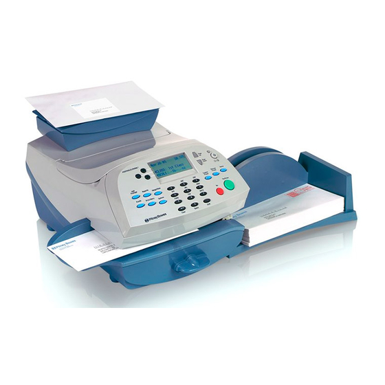
Pitney Bowes DM100i Series Service Manual & Parts List
Pitney bowes dm100i/dm200i series mailing system service manual & parts list
Hide thumbs
Also See for DM100i Series:
- Operator's manual (218 pages) ,
- Quick install manual (48 pages) ,
- Reference manual (33 pages)

Related Manuals for Pitney Bowes DM100i Series


Summary of Contents for Pitney Bowes DM100i Series
- Page 1 DM100i/DM200i series Mailing System Service Manual & Parts List FORM SDT345A (8-07)
- Page 2 The title, copyright and all other proprietary rights in this document are vested in Pitney Bowes Limited and no part of it may be reproduced in any form without the written permission of Pitney Bowes Limited.
-
Page 3: Table Of Contents
3.4 - Lower Delivery Unit Related .............. 3-12 3.5 - PCBs ....................3-18 SecTION 4 Troubleshooting 4.1 - Introduction ..................4.2 - Troubleshooting Tables ..............Parts List SecTION 5 Parts List ......................SDT345A DM100i Series Service Manual & Parts List... - Page 4 • Contents SDT345A DM100i Series Service Manual & Parts List...
-
Page 5: Introduction
1 • Introduction Introduction • 1 PURPOSe This document provides the information necessary to support the installation and site repair of the DM100i/DM200i Series Digital Mailing System. eQUIPMeNT cOVeReD This manual applies to the DM100i/DM200i Series and the kits required for digital mailing system operation. -
Page 6: Equipment Safety
1 • Introduction ● Use one hand when reaching into a circuit. By keeping one hand free, lethal current is less likely to pass through vital organs. Observe this rule when connecting or disconnecting plugs or leads, and when making any adjustments on a live circuit. Don’t underestimate the danger of shock: 1mA (1/1000 ampere) is uncomfortable;... - Page 7 Introduction • 1 WARNING! Always be sure the equipment is unplugged before you make any attempt to perform the maintenance outlined in this manual. If you must work on a "live" machine, note that line potential is present at the power panel and the motherboard.
- Page 8 1 • Introduction SDT345A DM100i/DM200i Series Service Manual & Parts List...
-
Page 9: Specifications
2 • Specifications 2 • Specifications MATeRIAL SPecIFIcATIONS Material Specifications Material (see figure below) Minimum Size 127 mm x 76 mm Maximum Size: 381 x 330 mm Minimum Flap Depth: 22 mm Maximum Flap Depth: 76 mm Minimum Thickness: 0.18 mm Maximum Thickness: 9.5 mm Maximum Stack Height for Mail: 60 mm IMPORTANT: For best results, always make... -
Page 10: Machine Specification
2 • Specifications MAchINe SPecIFIcATIONS Size of Base Model: 215mm H x 345mm W x 400mm D Size of Base Model with Scale: 230mm H x 345mm W x 400mm D Size of Base Model with Scale and Moistener: 230mm H x 470mm W x 400mm D Stacker: The stacker adds 265mm to the width of the system. -
Page 11: Removal & Replacement
3 • Removal & Replacement 3 • Removal & Replacement external covers 3.0.0 Removing the Upper Cover Unit 1) Open the open/closed cover [1]. 2) Remove the 2 screws [1]. 3) Remove the screw [1], and detach the upper cover unit [2]. 4) Free the harness [2] from the 2 harness guides [1]. - Page 12 3 • Removal & Replacement 3.0.1 Removing the Control Panel Unit 1) Remove the upper cover unit. (See A-1 Removing the Upper Cover Unit) 2) Remove the 4 screws [1]. 3) Remove the control panel unit [1]. SDT345A DM100i/DM200i Series Service Manual & Parts List...
- Page 13 3 • Removal & Replacement 3.0.2 Removing the Lower Cover Unit 1) Remove the upper cover unit. (See A-1 Removing the Upper Cover Unit) 2) Pull out the lever [1]. 3) Remove the 2 screws [1] on the left side of the main body.
-
Page 14: Carriage Unit Related
3 • Removal & Replacement carriage Unit Related 3.1.0 Removing the Carriage Unit Carriage unit consists of the carriage, the guide rail of the carriage and the carriage motor. 1) Remove the upper cover unit. (See A-1 Removing the Upper Cover Unit) 2) Remove the lower cover unit. - Page 15 3 • Removal & Replacement 6) Disconnect the connector [1]. Remove the screw [2] and detach the interface connector unit [3]. 7) Remove the screw [1]. Unlock the flexible cable connector and detach the flexible cable [2]. 8) Remove the screw [1]. 9) Disconnect the connector [1], and remove the screw [2].
- Page 16 3 • Removal & Replacement 10) Slide the carriage [1] to the front, then move the carriage unit [2] to the rear side, and remove the carriage unit [2]. 3.1.1 Removing the Carriage Drive Motor 1) Remove the carriage unit. (See B-1 Removing the Carriage Unit) 2) Remove the screw [1] and detach the carriage drive motor [2].
- Page 17 3 • Removal & Replacement 3.1.2 Removing the Head Holder Unit 1) Remove the carriage drive motor. (See B-2 Removing the Carriage Drive Motor) 2) Remove the screw [1], and detach the carriage drive rail [2]. 3) Unlock the hook [1] of the flexible cable cover.
- Page 18 3 • Removal & Replacement 3.1.3 Adjustment at installation of the carriage drive belt The tension adjustment of the belt is necessary after the carriage drive belt is exchanged. 1) Loosen the screw [1]. 2) Adjust belt tension at the hook [1] so that the tension falls in the tolerance.
-
Page 19: Purge Unit Related
3 • Removal & Replacement Purge Unit Related 3.2.0 Removing the Waste Ink Tank Unit Waste ink tank unit consists of the ink tank case and the ink absorption sheet. 1) Remove the lower cover unit. (See A-3 Removing the Lower Cover Unit) 2) Remove the waste ink tank unit. - Page 20 3 • Removal & Replacement 3.2.2 Removing the sensor PCB (1) 1) Remove the purge unit. (See C-2 Removing the Purge Unit) 2) Remove the 2 hooks, and detach the cover [1]. 3) Remove the 2 screws [1], connector [2], and detach the sensor PCB (1) [3].
- Page 21 3 • Removal & Replacement 3.2.3 Removing the Purge Motor Unit 1) Remove the purge unit. (See C-2 Removing the Purge Unit) 2) Remove the 2 hooks, and detach the cover [1]. 3) Unlock the hook [1], and remove the 2 gear [2]. 4) Disconnect the connector [3].
-
Page 22: Lower Delivery Unit Related
3 • Removal & Replacement Lower Delivery Unit Related 3.3.0 Removing the Lower Delivery Unit 1) Remove the upper cover unit. (See A-1 Removing the Upper Cover Unit) 2) Remove the lower cover unit. (See A-3 Removing the Lower Cover Unit) caution Do a pressure release of the delivery unit prior to removing... - Page 23 3 • Removal & Replacement 6) Remove the screw [1] on the right side of the main body, and detach the lower delivery unit [2]. 3.4 Upper delivery Unit Related 3.4.0 Removing the Encoder Sensor 1) Remove the upper cover unit. (See A-1 Removing the Upper Cover Unit) 2) Remove the connector [1] and screw [2], and detach the encoder sensor.
- Page 24 3 • Removal & Replacement 3.4.1 Removing the Delivery Motor 1) Remove the purge unit. (C-2 Removing the purge unit) 2) Disconnect the connector [1], and remove the harness [2] from the 5 harness guides [3]. 3) Remove the 2 screws [1] from rear frame. 4) Remove the delivery motor [1].
- Page 25 3 • Removal & Replacement 3.4.3 Removing the delivery belt 1) Remove the upper cover unit. (A-1 Removing the Upper Cover Unit) caution Do a pressure release of the delivery unit prior to removing the delivery belt. 2) Loosen the screw [1] temporarily and fix the screw [1] again while compressing the spring [2] to lower the tension.
- Page 26 3 • Removal & Replacement 5) Remove the rail [1] and bushing [2]. 6) Remove the 4 screws [1], and detach the upper delivery unit [2]. 3-16 SDT345A DM100i/DM200i Series Service Manual & Parts List...
- Page 27 3 • Removal & Replacement 3.4.5 Removing the encoder 1) Remove the upper delivery unit. (See E-5 Removing the Upper Delivery Unit) 2) Remove the screw [1], and detach the encoder cover [2]. 3) Remove the screw [1], and detach the encoder [2]. caution holding the encoder, with hand, hold it as shown.
-
Page 28: Pcbs
3 • Removal & Replacement PcBs 3.5.0 Removing the Main PCB 1) Remove the upper cover unit. (See A-1 Removing the Upper Cover Unit) 2) Disconnect the all connector [1] and flexible cable [2] on the main PCB. 3) Remove the 3 screws [3] on the main PCB, and detach the main PCB [4]. - Page 29 3 • Removal & Replacement 3.5.2 Removing the DC Power Supply Unit 1) Remove the upper cover unit. (See A-1 Removing the Upper Cover Unit) 2) Disconnect the 2 connectors [1], and remove the harness from the harness guide [2]. 3) Remove the screw [3], and detach the open/ closed cover sensor [4].
- Page 30 3 • Removal & Replacement 3-20 SDT345A DM100i/DM200i Series Service Manual & Parts List...
-
Page 31: Troubleshooting
4 • Troubleshooting 4 • Troubleshooting Introduction This chapter explains how to troubleshoot the DM100i and DM200i. It includes troubleshooting charts and a list of error codes and their meanings. 4.0.1 General Troubleshooting Before troubleshooting the equipment, check that the customer's material falls within the specifications published in Chapter 2 of this manual. - Page 32 4 • Troubleshooting Table 4-1 Power ON and Initialization Faults errors checkpoints Possible causes/Solutions Mailing machine Does the cord show obvious signs of wear? Replace the power cord. is connected Does another cord work? to power, but Is the power cord connected to a functioning Check wall outlet.
- Page 33 4 • Troubleshooting Table 4-2 Keyboard and Display Faults Fault checkpoints Possible causes/Solutions Keyboard Wiring from keyboard to J4. Keyboard PCB. Poor connection at keyboard, wiring and failure. Does not connection at Main Logic Board, J4. respond. No display. Machine may be in sleep mode. Is front panel Press any key to wake unit.
- Page 34 4 • Troubleshooting Table 4-3 Mailing Machine Transport Faults Fault checkpoints Possible causes/Solutions Operator error. Operator may be feeding piece improperly. Instruct operator to position envelope top edge against rear wall and slide it to right. Interlocks. Are cartridge access cover and lower transport An error message should display if either closed? interlock is open.
- Page 35 4 • Troubleshooting Table 4-4 Printing Faults errors checkpoints Possible cause/Solution No print out of In some cases, the print head may dry out or Complete install. box. be cold from shipment. This could result in a no After install is complete, remove ink print condition.
- Page 36 4 • Troubleshooting Table 4-4 Printing Faults (continued) errors checkpoints Possible cause/Solution Poor print Follow steps at right. Remove the printhead and check for bent pins. from used ink Pins are normally angled downward. cartridge. Make sure printhead is correctly installed. Check printhead harness and connection at J13.
- Page 37 4 • Troubleshooting Table 4-4 Printing Faults (continued) errors checkpoints Possible cause/Solution Poor print with Purge. Perform a “B” purge and run a test print. new ink cartridge. Normally two such purges will result in a clear, crisp print. If not, you can try up to three more purges.
- Page 38 4 • Troubleshooting Table 4-5 Print carriage Faults errors checkpoints Possible cause/Solution PS1 fails to sense envelope or tape lead edge. Check for debris in transport path. Print carriage Carriage drive belt. Inspect belt and pulleys. Check that belt is fails to move from centered on pulleys and fully engages loop on home to print...
- Page 39 4 • Troubleshooting Table 4-6 Moistener Faults Problem Possible cause Solution envelopes don’t Incorrect feeding. Check that operator is sliding envelope flap under blue seal. edge of feed deck. If this is not done, moistener can’t wet flap. Low sealant level. Check sight glass on moistener tank.
- Page 40 4 • Troubleshooting Table 4-8 Modem/connection Faults Problem Possible cause Solution Machine fails System not connected to working Make sure the phone cord is firmly connected to a to connect to analog phone line. single line analog phone jack. The term analog phone Postage By line refers to a RJ11C or RJ11W compatible (single Phone Data...
- Page 41 4 • Troubleshooting Table 4-8 Modem/connection Faults (continued) Problem Possible cause Solution Machine fails changing the modem speed: Version 8.60 Meters are built with a default Modem to connect tp Initialization String setting, as follows: Postage By ATE0&K0M1X4W2S9=50S7=90^M Phone Data Using the following Key sequence will take you to the center: No dial screen which allows you to edit this string:...
- Page 42 4 • Troubleshooting Table 4-9 Integrated Scale Faults Problem Possible cause Solution Scale problems at The scale line is not showing or Put in for a download. time of install. an error code (e.g., 1103, 11F6) displays Try steps at right. Try uploads and downloads.
- Page 43 4 • Troubleshooting Table 4-10 common error Messages Error Action 2003 and 2004 Startup error. Reboot system. 220C Time out error. Reboot system. 24A4 or 24A5 Reboot. Leave system off for a minimum of one minute. A replacement print head will not resolve these errors.
- Page 44 4 • Troubleshooting Table 4-10 common error Messages (continued) Error Action DE00 When trying to connect with the Data Center, either PbP is not set up to communicate with the meter or there is some other type of network problem. Confirm the meter is installed at PbP, that the cusomer has not reached his or her credit limit, and that there are funds available to download.
- Page 45 4 • Troubleshooting Table 4-10 common error Messages (continued) Error Action No Dial Tone See Table 4-8. Print Head/Ink See Table 4-4. Tank not Detected Rate Manager Not See Table 4-9. Initialized Weight Over See Table 4-9. Capacity Error on DM400c. Happens when transport is opened? Clear envelopes from paper path 37B6 and reboot.
- Page 46 4 • Troubleshooting Table 4-11 Motion control Processor (McP) Related error codes (16xx codes) Error Description 1600 No Error 1601-1627 Reserved 1628 Failed to Feed 1629 Printer Not Ready 162A TAR2 Exit Jam 162B Printer Error 162C Transport Jam 162D TAR1 Exit Jam 162E Tape Jam...
- Page 47 4 • Troubleshooting Table 4-11 Motion control Processor (McP) Related error codes (16xx codes) continued 165F Invalid Motor State 1660 Invalid Position Move 1661 Error erasing flash memory for download 1662 Error saving flash memory after download 1663 Servo Position Error 1664 I2C Bus Error 1665...
- Page 48 4 • Troubleshooting Table 4-11 Motion control Processor (McP) Related error codes (16xx codes) continued 16B6 Feeder Hardware Not Detected 16B7 The Requested Operation is invalid 16B8 The Feeder has not enumerated in a timely fashion 16B9 The firmware update has failed. 16BA No firmware has been installed in the UIC.
- Page 49 4 • Troubleshooting I-Button Specific PSD error codes Group 2 (21xx): This class of errors is reported by the Janus UIC when there are image generator errors. Table 4-12 DM100i/DM200i Image Generator errors (22xx) Error Description 2201 Font, graphic, barcode, or text ad component had wrong schema version 2202 Too many “indicia”...
- Page 50 4 • Troubleshooting Table 4-12 DM100i/DM200i Image Generator errors (22xx) continued 221B A register group has a field size that is too big OR the number of VCR definitions for a graphic doesn’t match the sum of all the register field lengths for the graphic OR the total number of VCRs for a region map is more than the max allowed.
- Page 51 4 • Troubleshooting Table 4-13 DM100i/DM200i Print head Security errors (23xx) Error Description 2300 Version mismatch error 2301 Programming failure 2302 Communication error 2303 Fatal communication error 2304 Communication timeout error 2305 Seed mismatch error 2306 Fatal programming error Table 4-14 DM100i/DM200i Print Manager errors (24xx) Error Description 2400...
- Page 52 4 • Troubleshooting Table 4-15 DM100i/DM200i BOB Task errors (25xx) Error Description 2501 Unknown intertask message or script request 2502 PSD failed to reply to a message 2503 PHC failed to reply to a message 2504 External card failed to reply to a message 2505 General communication failure 2506...
- Page 53 4 • Troubleshooting Table 4-15 DM100i/DM200i BOB Task errors (25xx) continued 2529 Unknown component ID in the print zone packed byte parameter 252A Unknown function ID in the print zone packed byte parameter 252B Message resent maximum number of times without response 252C Trouble retrieving a test print from FLASH 252D...
- Page 54 4 • Troubleshooting SDT345A DM100i/DM200i Service Manual & Parts List 4-24...
-
Page 55: Parts List Section
5 • Parts List 5 • Parts List Parts No. Name Photograph Recommended Note Initial Stock Item QC1-4685 GUIDE, CABLE QC1-4692 ROLLER, PRESS, UPPER QC1-4706 KNOB, RELEASE QC1-4727 ROLLER, LOWER 1, SEAL QC1-4728 ROLLER, LOWER 2, SEAL QC1-4787 SHEET, DRAIN QC1-5127 COVER, TOP QC1-5128... - Page 56 5 • Parts List QC1-5129 COVER, DECK QC1-5130 FOOT, RUBBER QK1-0716 SENSOR UNIT QK1-0721 MOTOR, DC 24V QK1-0726 MOTOR, DC 27V QK1-0731 CONTROL PANEL UNIT Does not come with bezel. QK1-0732 MODEM UNIT (UK) QK1-0734(Int) QL2-0670 ENCODER ASSY QL2-0687 COVER ASSY, BOTTOM SDT345A DM100i/DM200i Service Manual &...
- Page 57 5 • Parts List QM2-1335 TRANSPORT UNIT, UPPER QM2-1336 ROWEL UNIT QM2-1337 PULLEY UNIT, TENSION QM2-1338 REGISTRATION UNIT QM2-1339 TRANSPORT UNIT, LOWER QM2-1341 GUIDE, TRANSPORT QM2-1342 SLIDE PLATE ASSY QM2-1343 WHEEL ASSY, SLIDE, 1 QM2-1344 WHEEL ASSY, SLIDE, 2 SDT345A DM100i/DM200i Service Manual & Parts List...
- Page 58 5 • Parts List QM2-1345 WHEEL ASSY, SLIDE, 3 QM2-1346 PRESS ROLLER LOWER UNIT QM2-1347 PURGE UNIT QM2-1352 CARRIAGE UNIT QM2-1353 ADJUSTER UNIT, BELT, CARRIAGE QM2-1354 ADJUSTER UNIT, 1, TENSION QM2-1355 ADJUSTER UNIT, 2, TENSION QM2-1356 CONNECTOR ASSY QM2-1357 SENSOR UNIT, COVER, SDT345A DM100i/DM200i Service Manual &...
- Page 59 5 • Parts List QM2-1360 PRESS ROLLER UNIT QM2-1361 SENSOR UNIT, EN- CODER QM2-1364 PRINT HEAD UNIT QM2-1374 WASTE INK TANK UNIT QM2-1377 TANK COVER ASSY QM2-1406 ENCODER PCB UNIT QM2-1420 CABLE, MODEM QM2-1422 DC POWER SUPPLY UNIT SDT345A DM100i/DM200i Service Manual & Parts List...
- Page 60 5 • Parts List QM2-1425 CONTROLLER PCB This part is not UNIT Parameterized. Cheaper to re- place machine. Not available as a spare part. QU1-0066 PULLEY, 40T QU1-0067 PULLEY, 16T/80T QU1-2118 SPRING, COMPRES- SION QU1-2119 SPRING, TORSION QU1-2120 SPRING, TORSION QU1-2121 SPRING, TORSION QU1-2122...
- Page 61 5 • Parts List QU1-2126 SPRING, TORSION QU1-3024 PULLEY, IDLER QU1-3025 PULLEY, DRIVE QU1-3026 BELT, FEED QU1-3027 BELT, TIMING QU1-3028 BELT, TIMING QU1-6014 WHEEL, SLIDE QU1-6015 WHEEL VT2-5018 SPACER SDT345A DM100i/DM200i Service Manual & Parts List...
- Page 62 5 • Parts List WG8-5364 PHOTO-INTERRUPTER XB1-2300-605 SCREW, MACHINE M3X6 XD2-1100-242 RING, E, Φ2.4 XD2-1100-502 RETAINING RING (E- TYPE) XG9-0531 BEARING SDT345A DM100i/DM200i Service Manual & Parts List...
Need help?
Do you have a question about the DM100i Series and is the answer not in the manual?
Questions and answers