Table of Contents
Advertisement
Advertisement
Table of Contents

Related Manuals for Safety Vision SVR-4100


Summary of Contents for Safety Vision SVR-4100
- Page 1 AdvAnced Mobile digitAl video RecoRdeR...
-
Page 2: Important Notices
This material is confidential and the property of Safety Vision. It is shared with your company for the sole purpose of helping you with the operation of the described equipment. -
Page 3: Table Of Contents
Table of Contents Components SD Card Insertion Installation Panic Button (SV-4100-PANIC) Remote Control Live View Menu Navigation Video Playback Exporting Video Files Configuration System Menu Record Menu Network Menu Event Menu Peripheral Menu System Information Appendix A: Web Application Manager Appendix B: Specifications Appendix C: Recording Time Calculator Appendix D: Dimensions... -
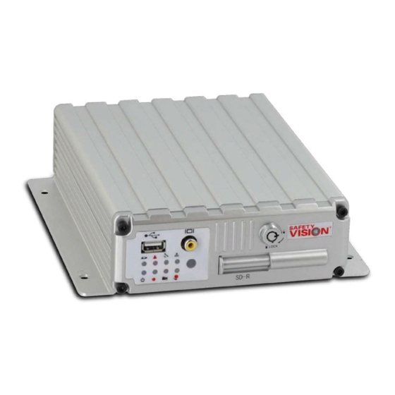
Page 4: Components
- Insert a USB flash drive to download events quickly without having to remove the Secure Digital (SD) card. 2 - External Monitor Output - Attach an external monitor to the SVR-4100 with an RCA plug here to configure the mobile digital video recorder (MDVR). 3 - Door Lock - The Door Lock secures the door over the SD card slot for security. -
Page 5: Sd Card Insertion
SD Card Insertion To insert an SD card into the SVR-4100: 1. Insert the key and turn it counterclockwise. 2. Push the SD card slot door firmly to the right. 3. Insert an SD card into the SVR-4100 label-side up, with the notch to the right, until it clicks in place. - Page 6 SvR-4100 USeR gUide Wiring Harness Connections Recommended Sensor Connections (12V) Stop Arm Lights (school bus) Sensor 8 Amber Warning Lights (school bus) Sensor 7 Sensor 6 Door (or wheel chair lift) Sensor 5 Head Lights Sensor 4 Event Button (see note)
-
Page 7: Installation
Ensure that the front panel of the MDVR remains accessible and there is a minimum 2.5 inches of clearance for cables.. Do not install the SVR-4100 in an area of the vehicle cabin that could interfere with the safe operation of the vehicle. -
Page 8: Remote Control
SvR-4100 USeR gUide Remote Control The SVR-4100 remote control is used to navigate through the configuration menus or to control video playback on an external monitor. Point the remote control at the IR receiver on the front panel of the SVR-4100 to make selections. - Page 9 3 - Navigation Buttons - Use the four arrow keys to navigate between input fields or menu selections when configuring the system. Use the Enter key in the center of the arrow keys to make selections. During video playback the left and right arrow keys can be used to rewind or fast-forward.
-
Page 10: Live View
SvR-4100 USeR gUide Live View Attach an external monitor to the front RCA port (or install a permanent external monitor as shown in the Installation diagram) while the SVR-4100 is on to view the Live View. Menu Navigation For more information on setting... -
Page 11: Video Playback
START/END TIME: Select a specific time when the video started recording. The SVR-4100 searches the hour follow- ing the time entered in this field. For example, enter “14:00:00” searches for video from 2:00 pm to 3:00 pm. - Page 12 SvR-4100 USeR gUide File list After selecting criteria from the File Search menu, the File List menu appears. The following fields are displayed: All Files SEL: Use the arrow and Enter keys on the remote control to select or unselect each file.
-
Page 13: Exporting Video Files
Exporting Video Files Video files can be exported to a USB thumb drive inserted into the USB port on the front of the SVR-4100. To manually export video files, use the following procedure: Select each file you want to export in the SEL column. -
Page 14: Configuration
(DD/MM/YYYY), or big endian (YYYY-MM-DD) date formats. The SVR-4100 must have a clear GPS signal to syncronize its time via GPS, Time: Use the number keys on the remote to set the current time manually. or it must have network access to FORMAT: Select from 12 hour (12H) or 24 hour (24H) time formats. - Page 15 (ON/OFF TYPE: IGNITION) SHUT DOWN DELAY MIN: Use the number keys on the remote control to manually enter the time (in minutes) that the SVR-4100 continues to record after the vehicle has been powered down. BUZZER SWITCH: Turn an audible buzzer on (ON) or off (OFF) when an event occurs.
- Page 16 5 characters. VEHICLE S/N FOR CMS: Enter a 7 digit facility-defined serial number that identifies this specific SVR-4100 in SafetyNet 4.0 Central Management System (CMS).
- Page 17 SloW FoRMAt (to search for bad storage sectors before formatting) Select FoRMAt. A Warning message appears. Select SURe. The format process begins. When finished, the SVR-4100 restarts automatically. Formatting a device erases all data, including recorded video. Use with caution.
- Page 18 The MCU update function is not active at this time. Select UPGRADE. The update process begins. The SVR-4100 first checks for an appropriate upgrade file. If one is detected, it automatically restarts. Upon restarting, the SVR-4100 displays “System Updating...” on the external monitor while it installs the upgrade.
- Page 19 User Security The User Security menu controls the password needed to access the SVR- 4100 menus. PASSWORD ENABLE: Select ON to require a password to access the SVR- 4100’s menus; select OFF to disable this feature and allow free access. SELECT USER: Select a user level to set a password for: - ADMINISTRATOR: has full access rights,...
- Page 20 The Config menu allows you to export to or import from a USB drive all of the SVR-4100’s settings, which is useful when configuring multiple units in the same manner or creating a backup. DEFAULT SETTINGS: Select RESTORE to revert all settings tot he factory defaults.
- Page 21 System log The System Log menu allows the user log to be exported or deleted. The system log file contains a log of which users accessed the SVR-4100s configuration menus and at what time and date. To export the user log file: Insert a USB flash drive into the front USB port.
-
Page 22: Record Menu
VIDEO TYPE: Select NTSC or PAL. RECORD MODE: Select GENERAL to began full-time recording automatically when the SVR-4100 is powered on. Select TIMER to begin recording as defined in the Time Record menu. Select EVENT to record only when an event is triggered. - Page 23 options (Page 2) METADATA CAPTURE: Select ON to record meta-data with recorded video. Select OFF to record video only. RECORD FILE TIME: Select 15, 30, 45 or 60 minute file packing sizes (optional) SD OVERWRITE: Select ON to overwrite the oldest video existent on the storage media when storage space is near capacity.
- Page 24 ACCELERATION: The acceleration of the vehicle as determined by the internal accelerometers. TEMPERATURE: The internal temperature of the SVR-4100. FIRMWARE VERSION: The current firmware version installed on the SVR- 4100. GPS INFO: The direction the vehicle is traveling as determined by the optional...
- Page 25 camera Settings The Camera Setting menu controls which cameras are recorded and displayed in the live view. Select the following for each camera: ENABLE: Select ON to enable recording of this camera. NAME: Enter an optional alphanumeric name for each specific camera. AUDIO: Select ON to enable audio recording for this camera.
- Page 26 SvR-4100 USeR gUide Record Setting The Record Setting menu controls the framerate and resolution of recorded video. Each camera’s parameters can be set independently. Select the following for each channel: RES: Select the resolution of this camera. Select from D1 (704×576), HD1 (704×288), or CIF (354×288).
- Page 27 SUB-STREAM MODE (MODE2 only): Select ADAPT or FIX. Selecting ADAPT allows the SVR-4100 to automatically select the optimal bit-rate; selecting FIX sets the bit-rate to the entry in the BIT field. Adjust these settings to achieve the optimal data transfer rate to image quality ratio.
- Page 28 SvR-4100 USeR gUide Schedule The Schedule menu allows to the SVR-4100 to begin and end recording automatically based on a timed schedule. In the DATE column to select from EVERY (every day), WEEKDAY (Monday thru Friday) or individual days. Asterisks (******) disable automatic recording during the selected times on that line.
- Page 29 Settings The Other Settings menu controls if a special Safety Vision watermark appears on recorded video files. This watermark improves the validity of recorded video as evidence since it is not as easily tampered with. WATERMARK: Select ON to insert a watermark on all recorded video.
-
Page 30: Network Menu
SVR-4100 interacts with computers and wireless central management systems. local The Local menu controls network information for the SVR-4100 unit when configuring networks. Use the number keys on the remote control to enter the following: IP: Static internet protocol (IP) address of the SVR-4100. - Page 31 The Network screen controls how the SVR-4100 interfaces with an optional cellular device (in development at this time).
- Page 32 SvR-4100 USeR gUide Server network The Server Network screen controls central management system (CMS) server addresses that the SVR-4100 networks with (in development at this time).
- Page 33 WiFi The WiFi menu controls settings of the wireless access point the SVR-4100 communicates with. Select ON in the WIFI field and use the number keys on the remote control to enter the following: IP: Static IP address of the access point.
- Page 34 SvR-4100 USeR gUide FtP Settings The FTP Settings screen controls central management system (CMS) server addresses that the SVR-4100 networks with. CMS integration is in development at this time.
-
Page 35: Event Menu
Sensor The Sensor menu controls each sensor input that triggers events. The SVR-4100 supports up to eight inputs and can configure each one individually. Use the remote control to configure the following for each... - Page 36 SvR-4100 USeR gUide Sensor trigger Action Select NEXT PAGE on the Sensor menu to access this menu. The Sensor trigger menu allows a chan- nel to be displayed in fullscreen while us- ing Live View when an event is triggered.
- Page 37 For each alarm type, select ON or OFF for outputs 1 through 4 (OUT1 to OUT4). An ERROR type alam occurs when the SVR-4100 or its storage media require service. A STORAGE type alarm occurs when the percentage entered in the SD STORAGE ALARM field in the Other Settings menu is achieved.
- Page 38 THRESHOLD: Use the number keys on the remote control to enter the speed at which the event is triggered. ALARM: Select ON to enable the ALM LED on the front of the SVR-4100 when the For more information about connecting the SVR-4100 to a vehicle THRESHOLD speed is reached and an event is triggered.
- Page 39 (in Gs) for each axis (X, Y, and Z) at which the event is triggered. ALARM: Select ON to enable the ALM LED on the front of the SVR-4100 when the THRESHOLD force is reached and an event is triggered. This LED continues to flash after an event is triggered until the configuration menus are accessed.
- Page 40 EN: Select ON to enable the event. Select OFF to disable it. ALARM: Select ON to enable the ALM LED on the front of the SVR-4100 when the event is triggered. This LED continues to flash after an event is triggered until the configuration menus are accessed.
- Page 41 SVR-4100 can continue to receive the voltage indicated in the VOLTAGE field before disconnecting from the CMS. SHUT DOWN DELAY: Select the time, in minutes, that the SVR-4100 can continue to receive the voltage indicated in the LOW VOLTAGE field before...
- Page 42 SvR-4100 USeR gUide Alarm of Panic button The Alarm of Panic Button menu controls events relating to the panic button module. Use the remote control to configure the following: EN: Select ON to enable the panic button module. Select OFF to disable it.
-
Page 43: Peripheral Menu
Peripheral Menu The Peripheral Menu contains parameters that control optional connected peripheral accessories. ext. com. Setup The Ext. Com. Setup menu enables optional COM3 and COM4 connections to a control panel, acceleration sensor, or panic button. Use the remote control to configure the following for each individual input: COM3: Select the device connected to the 485A-1 and 485B-1 terminals. -
Page 44: System Information
System, History, Modules, and Authorized menus. These menu options display unique information and history about the SVR-4100 unit. System The System menu displays the firmware version and information on the SD card. FIRMWARE VERSION: The version of firmware currently installed. - Page 45 History info The History Info menu consists of three pages. Select CLEAR next to any record to reset it. HIGHEST SPEED IN HISTORY: Displays the highest obtained speed, including the date and time it was recorded (assuming speed data is collected). MILEAGE OF HISTORY: Displays the total amount of miles (or kilometers) driven.
- Page 46 SvR-4100 USeR gUide Modules The Modules menu displays the status of optional installed modules. GPS MODULE: Displays NORMAL if a GPS module is installed; NONE is one is not. GPS SIGNAL: Displays if the GPS signal received is valid. WIFI MODULE: Displays NORMAL if a Wi- Fi module is installed;...
-
Page 47: Appendix A: Web Application Manager
Appendix A: Web Application Manager The SVR-4100 includes a web server, called the Web Application Manager, that can be accessed with a Windows based PC and browser. The Web Application Manager includes Live View, Playback, Setup (Configuration) and Maintenance menus. It provides much of the same functionality as an external monitor and remote control when these accessories are not available or practical. - Page 48 SvR-4100 USeR gUide live The Live tab displays the current camera’s views similar to the Live View on an external monitor, with the added features of the Play & Control menu in the lower right corner of the screen: OPEN WINDOW: Refreshes camera feeds when configuring camera views.
- Page 49 SAVE to complete parameter changes. Maintenance The Maintenance tab allows you to reboot or shut down the connected SVR-4100, in addition to upgrading the firmware. Actions performed appear in a log displayed in the center of the screen (which can be cleared by clicking C).
-
Page 50: Appendix B: Specifications
SvR-4100 USeR gUide Appendix B: Specifications SVR-4100 Embedded real-time Linux Configuration IR remote (included); web browser via Ethernet port Video Standard NTSC / PAL selectable Audio/Video Inputs 4 channels Audio/Video Output 1 channel, RCA in front of unit, BNC on AV cable harness Audio/Video Compression H.264... -
Page 51: Appendix C: Recording Time Calculator
Appendix C: Recording Time Calculator Resolution Quality Cameras Hours of Recording 4 - Medium 4 - Medium 4 - Medium 4 - Medium Half D1 4 - Medium Half D1 4 - Medium Half D1 4 - Medium Half D1 4 - Medium 4 - Medium 4 - Medium... -
Page 52: Appendix D: Dimensions
SvR-4100 USeR gUide Appendix D: Dimensions Minimum cable clearance 5.97 in. 7.48 in. - Page 53 1-Year new Product Warranty Safety Vision, LLC (“SV”) makes the following limited warranty, which is effective at the time of the original end-user purchase. Note: Optional warranty products are available for all SV products and may be pur- chased at the time of the original end-user purchase or any time during the original Limited 1-Year New Product Warranty period.
- Page 54 SvR-4100 USeR gUide FCC Compliance Statement NOTE This device has been tested and found to comply with the limits for a Class A digital device, pursuant to part 15 of the FCC Rules. These limits are designed to provide reasonable protection against harmful interference when the equip- ment is operated in a commercial environment.
- Page 56 CORPORATE HEADQUARTERS 6100 W. Sam Houston Pkwy. N. Houston, TX 77041-5113 Toll Free: 800.880.8855 Main: 713.896.6600 Fax: 713.896.6640 www.safetyvision.com 2/12...
Need help?
Do you have a question about the SVR-4100 and is the answer not in the manual?
Questions and answers