Juniper MX480 Hardware Manual
3d universal edge router
Hide thumbs
Also See for MX480:
- Hardware manual (519 pages) ,
- Quick manual (31 pages) ,
- Manual (6 pages)

Related Manuals for Juniper MX480


Summary of Contents for Juniper MX480
- Page 1 MX480 3D Universal Edge Router Hardware Guide Modified: 2017-12-18 Copyright © 2017, Juniper Networks, Inc.
- Page 2 END USER LICENSE AGREEMENT The Juniper Networks product that is the subject of this technical documentation consists of (or is intended for use with) Juniper Networks software. Use of such software is subject to the terms and conditions of the End User License Agreement (“EULA”) posted at http://www.juniper.net/support/eula/.
-
Page 3: Table Of Contents
MX480 Cable Management Brackets ........19... - Page 4 MX480 Host Subsystem Description ........25...
- Page 5 MX480 AC Power Supply Description ........100...
- Page 6 MX480 Router Rack Requirements ........
- Page 7 Installing an MX480 Router Overview ........187...
- Page 8 Initially Configuring the MX480 Router ......241 Initially Configuring the MX480 Router ....... . . 241 viii Copyright ©...
- Page 9 Installing an MX480 Dual-Wide MIC ........266...
- Page 10 Replacing an MX480 Routing Engine ........301...
- Page 11 Replacing Power System Components ......367 Replacing an MX480 AC Power Supply ....... . 367 Removing an MX480 AC Power Supply .
- Page 12 MX480 Chassis Serial Number Label ........461...
- Page 13 MX480 Chassis Lifting Guidelines ........
- Page 14 Agency Approvals for MX480 Routers ........519...
- Page 15 Figure 25: Typical FPCs Supported on the MX480 Router ....64 Figure 26: MX480 PIC Interface Port Mapping ......67 Figure 27: MX480 MIC Interface Port Mapping .
- Page 16 Unpacking the MX480 Router ........
- Page 17 Chapter 17 Connecting the MX480 Router to Power ......217 Figure 75: Connecting AC Power to the Router (110V) ..... 220 Figure 76: Connecting DC Power to the Router .
- Page 18 Figure 135: Installing a Routing Engine in an MX240 Router ....317 Figure 136: Installing a Routing Engine in an MX480 Router ....318 Figure 137: Installing a Routing Engine in an MX960 Router .
- Page 19 Figure 175: Serial Number ID Label ........461 Figure 176: MX480 Chassis Serial Number Label ......462 Figure 177: SCB Serial Number Label .
- Page 20 MX480 3D Universal Edge Router Hardware Guide Figure 182: 20-Port MIC Serial Number Label ......466 Figure 183: 40-Port MIC Serial Number Label .
- Page 21 Table 27: MX240 Supported Routing Engines ......44 Table 28: MX480 Supported Routing Engines ......44 Table 29: MX960 Supported Routing Engines .
- Page 22 Table 45: FPCs Supported by MX Series Routers ......65 Table 46: PICs Supported by MX240, MX480, and MX960 Routers ... 68 Table 47: MIC/MPC1 Compatibility .
- Page 23 Unpacking the MX480 Router ........
- Page 24 MX480 3D Universal Edge Router Hardware Guide xxiv Copyright © 2017, Juniper Networks, Inc.
-
Page 25: About The Documentation
® To obtain the most current version of all Juniper Networks technical documentation, see the product documentation page on the Juniper Networks website at http://www.juniper.net/techpubs/ If the information in the latest release notes differs from the information in the documentation, follow the product Release Notes. -
Page 26: Table 1: Notice Icons
MX480 3D Universal Edge Router Hardware Guide Table 1: Notice Icons Icon Meaning Description Informational note Indicates important features or instructions. Caution Indicates a situation that might result in loss of data or hardware damage. Warning Alerts you to the risk of personal injury or death. -
Page 27: Documentation Feedback
We encourage you to provide feedback, comments, and suggestions so that we can improve the documentation. You can provide feedback by using either of the following methods: Online feedback rating system—On any page of the Juniper Networks TechLibrary site , simply click the stars to rate the content, http://www.juniper.net/techpubs/index.html and use the pop-up form to provide us with information about your experience. -
Page 28: Requesting Technical Support
7 days a week, 365 days a year. Self-Help Online Tools and Resources For quick and easy problem resolution, Juniper Networks has designed an online self-service portal called the Customer Support Center (CSC) that provides you with the following features: Find CSC offerings: http://www.juniper.net/customers/support/... - Page 29 About the Documentation For international or direct-dial options in countries without toll-free numbers, see http://www.juniper.net/support/requesting-support.html Copyright © 2017, Juniper Networks, Inc. xxix...
- Page 30 MX480 3D Universal Edge Router Hardware Guide Copyright © 2017, Juniper Networks, Inc.
-
Page 31: Overview
PART 1 Overview System Overview on page 3 MX480 Release Notes on page 5 Chassis Components and Descriptions on page 9 Cooling System Components and Descriptions on page 21 Host Subsystem Components and Descriptions on page 25 Line Card Components and Descriptions on page 55... - Page 32 MX480 3D Universal Edge Router Hardware Guide Copyright © 2017, Juniper Networks, Inc.
-
Page 33: System Overview
Routing Engines, and Switch Control Boards (SCBs). The MX480 router is eight rack units (U) tall. Five routers can be stacked in a single floor-to-ceiling rack, for increased port density per unit of floor space. The router provides... -
Page 34: Table 4: Scb Comparison
DPCs supported, see the MX Series Interface Module Reference The MX480 supports up to 3 FPCs containing up to 6 PICs or up to 6 MPCs containing up to 12 MICs. For a list of the supported line cards, see the... -
Page 35: Mx480 Release Notes
(60-61V instead of 57V) under some conditions, such as when the load is nearly 100% and the operating temperature exceeds 40C. There is an input mode switch on each MX480 DC high capacity power supply, covered by a small plate. The input mode switch tells the system what capacity feed is... -
Page 36: Errata With The Mx480 Router Documentation
You need to insert the optics and fiber firmly until the latch is securely in place. [PR/98055] Do not mix AC and DC power supplies on an MX480 router. Mixing of AC supplies and DC supplies may damage your chassis. [PR/233340]... -
Page 37: Mx480 Release Notes
Table 5: Host Subsystem OFFLINE LED Label Color State Description On steadily Host is installed but the Routing Engine is offline. OFFLINE Host is not installed. Related Outstanding Issues with the MX480 Router on page 5 Documentation Copyright © 2017, Juniper Networks, Inc. - Page 38 MX480 3D Universal Edge Router Hardware Guide Copyright © 2017, Juniper Networks, Inc.
-
Page 39: Chassis Components And Descriptions
MX480 Router Hardware and CLI Terminology Mapping on page 12 MX480 Craft Interface Description on page 14 Alarm Relay Contacts on the MX480 Craft Interface on page 15 Alarm LEDs and Alarm Cutoff/Lamp Test Button on the MX480 Craft Interface on page 15... -
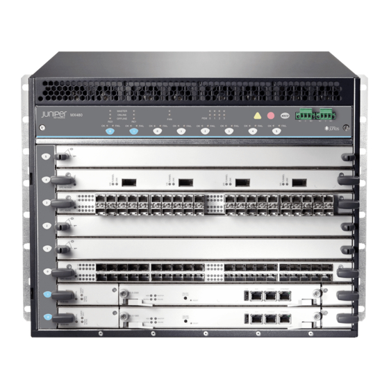
Page 40: Figure 1: Front View Of A Fully Configured Router Chassis
MX480 3D Universal Edge Router Hardware Guide Figure 1: Front View of a Fully Configured Router Chassis Figure 2: Rear View of a Fully Configured AC-Powered Router Chassis Copyright © 2017, Juniper Networks, Inc. -
Page 41: Mx480 Component Redundancy
MX480 Router Description on page 3 Documentation MX480 Midplane Description on page 26 MX480 Router Physical Specifications on page 119 MX480 Component Redundancy A fully configured router is designed so that no single point of failure can cause the entire system to fail. -
Page 42: Mx480 Router Hardware And Cli Terminology Mapping
MX480 Chassis Description on page 9 MX480 Router Hardware and CLI Terminology Mapping The MX480 router supports the components in Table 6 on page Table 6: MX480 Router Hardware Components and CLI Terminology Component Hardware Model Number CLI Name Description... - Page 43 Chapter 3: Chassis Components and Descriptions Table 6: MX480 Router Hardware Components and CLI Terminology (continued) Component Hardware Model Number CLI Name Description Fan tray FFANTRAY-MX480 “MX480 Cooling System Left Fan tray Description” on page 21 High-capacity fan tray FFANTRAY-MX480-HC...
-
Page 44: Mx480 Craft Interface Description
MX480 3D Universal Edge Router Hardware Guide Table 6: MX480 Router Hardware Components and CLI Terminology (continued) Component Hardware Model Number CLI Name Description AC power supply PWR-MX480-AC “MX480 AC Power Supply AC Power Entry Module Description” on page 100 PWR-MX480-1200-AC PS 1.2-1.7kW 100-240V AC... -
Page 45: Alarm Relay Contacts On The Mx480 Craft Interface
At least one SCB must be installed in the router for the craft interface to obtain power. Related Alarm LEDs and Alarm Cutoff/Lamp Test Button on the MX480 Craft Interface on Documentation page 15 MX480 Component LEDs on the Craft Interface on page 16... -
Page 46: Mx480 Component Leds On The Craft Interface
Host Subsystem LEDs on the MX480 Craft Interface on page 16 Power Supply LEDs on the MX480 Craft Interface on page 17 DPC and MPC LEDs on the MX480 Craft Interface on page 17 FPC LEDs on the MX480 Craft Interface on page 17... -
Page 47: Power Supply Leds On The Mx480 Craft Interface
Power supply is functioning normally. On steadily Power supply has failed or power input has failed. DPC and MPC LEDs on the MX480 Craft Interface Each DPC or MPC has LEDs on the craft interface that indicate its status. The LEDs, labeled through , are located along the bottom of the craft interface. -
Page 48: Scb Leds On The Mx480 Craft Interface
Related MX480 Craft Interface Description on page 14 Documentation Alarm LEDs and Alarm Cutoff/Lamp Test Button on the MX480 Craft Interface on page 15 Alarm Relay Contacts on the MX480 Craft Interface on page 15 Copyright © 2017, Juniper Networks, Inc. -
Page 49: Mx480 Cable Management Brackets
Figure 6: Cable Management Brackets Figure 7: Cable Management Brackets Installed on the Router Related Maintaining Cables That Connect to MX480 DPCs, MPCs, MICs, or PICs on page 434 Documentation Replacing the MX480 Cable Management Brackets on page 291 Copyright © 2017, Juniper Networks, Inc. - Page 50 MX480 3D Universal Edge Router Hardware Guide Copyright © 2017, Juniper Networks, Inc.
-
Page 51: Cooling System Components And Descriptions
CHAPTER 4 Cooling System Components and Descriptions MX480 Cooling System Description on page 21 MX480 Fan LED on page 23 MX480 Cooling System Description The cooling system consists of the following components: Fan tray Air filter The cooling system components work together to keep all router components within the... -
Page 52: Figure 9: Fan Tray
MX480 3D Universal Edge Router Hardware Guide The host subsystem monitors the temperature of the router components. When the router is operating normally, the fans function at lower than full speed. If a fan fails or the ambient temperature rises above a threshold, the speed of the remaining fans is automatically adjusted to keep the temperature within the acceptable range. -
Page 53: Mx480 Fan Led
Chapter 4: Cooling System Components and Descriptions Related MX480 Fan LED on page 23 Documentation Maintaining the MX480 Air Filter on page 415 Maintaining the MX480 Fan Tray on page 416 Troubleshooting the MX480 Cooling System on page 442 MX480 Fan LED Each fan has an LED that displays its status. - Page 54 MX480 3D Universal Edge Router Hardware Guide Copyright © 2017, Juniper Networks, Inc.
-
Page 55: Chapter 5 Host Subsystem Components And Descriptions
Each host subsystem has three LEDs that display its status. The host subsystem LEDs are located in the middle of the craft interface. Related MX480 Host Subsystem LEDs on page 26 Documentation Maintaining the MX480 Host Subsystem on page 418 Taking an MX480 Host Subsystem Offline Copyright © 2017, Juniper Networks, Inc. -
Page 56: Mx480 Host Subsystem Leds
Each host subsystem has three LEDs that display its status. The host subsystem LEDs are located on the upper left of the craft interface. For more information, see “Host Subsystem LEDs on the MX480 Craft Interface” on page Related MX480 Host Subsystem Description on page 25... -
Page 57: Mx480 Routing Engine Description
MX480 Router Description on page 3 Documentation MX480 Chassis Description on page 9 MX480 Dense Port Concentrator (DPC) Description on page 55 MX480 Modular Port Concentrator (MPC) Description on page 87 MX480 SCB Description on page 107 MX480 Flexible PIC Concentrator (FPC) Description on page 63... -
Page 58: Routing Engine Components
MX480 3D Universal Edge Router Hardware Guide Figure 13: RE-S-X6-64G Routing Engine Front View 1— Extractor clips 6— ONLINE/OFFLINE Button 2— Auxiliary port ( 7— SSD LEDs— DISK1 DISK2 3— Console port ( 8— Ports— USB1 USB2 4— Management port ( MGMT 9—... -
Page 59: Routing Engine Boot Sequence
Related MX480 Router Description on page 3 Documentation MX480 Routing Engine LEDs on page 38 MX480 Host Subsystem Description on page 25 MX480 SCB Description on page 107 RE-S-1800 Routing Engine Description for MX Series Figure 15 on page 30 shows the Routing Engine 1800. -
Page 60: Re-S-1800 Routing Engine Components
MX480 3D Universal Edge Router Hardware Guide Figure 15: RE-S-1800 Front View Auxiliary Ethernet port port slot 1 slot 2 Extractor clip Console Reset port port button Extractor clip RE-S-1800 Routing Engine Components on page 30 RE-S-1800 Routing Engine Boot Sequence on page 31... -
Page 61: Re-S-1800 Routing Engine Boot Sequence
Routing Engine LEDs. Table 14: Routing Engine LEDs Label Color State Description Blue On steadily Routing Engine is the Master. MASTER Green Blinking Indicates activity on the SSD or Compact Flash. STORAGE Copyright © 2017, Juniper Networks, Inc. -
Page 62: Re-S-X6-64G Routing Engine Description
MX480 3D Universal Edge Router Hardware Guide Table 14: Routing Engine LEDs (continued) Label Color State Description Green Blinking Routing Engine is transitioning online. ONLINE On steadily Routing Engine is functioning normally. OK/FAIL On steadily Routing Engine has failed. Related... -
Page 63: Re-S-X6-64G Routing Engine Boot Sequence
Routing Engine Specifications on page 35 Documentation Upgrading to the RE-S-X6-64G Routing Engine in a Redundant Host Subsystem on page 313 Upgrading to the RE-S-X6-64G Routing Engine in a Nonredundant Host Subsystem on page 319 Copyright © 2017, Juniper Networks, Inc. -
Page 64: Re-S-X6-64G Routing Engine Leds
MX480 3D Universal Edge Router Hardware Guide RE-S-X6-64G Routing Engine LEDs Each Routing Engine has five LEDs that indicate its status. The LEDs—labeled MASTER , and —are located on the faceplate of the Routing Engine. DISK1 DISK2 ONLINE OK/FAIL Table 15 on page 34 describes the functions of the Routing Engine LEDs. -
Page 65: Routing Engine Specifications
8 GB Gigabit 4 GB T1600 router in a Ethernet CompactFlash routing matrix: 9.6R2 card Standalone T640 or T1600 router:11.2 RE-C2600 2.6-GHz 16 GB Gigabit 4 GB TX Matrix Plus Ethernet CompactFlash router: 9.6R2 card Copyright © 2017, Juniper Networks, Inc. - Page 66 MX480 3D Universal Edge Router Hardware Guide Table 16: Routing Engine Specifications (continued) Routing Connection First Junos OS Engine Processor Memory to PFEs Disk Media Support RE-A-1800x2 1800-MHz 8 GB or 16 GB Gigabit 32 GB SSD 4 GB 10.4...
-
Page 67: Table 17: End-Of-Life Routing Engine Specifications
Pentium M Ethernet disk CompactFlash card NOTE: The memory in Table 16 on page 35 indicates the amount of total memory. To determine the amount of available memory, issue the show chassis routing-engine CLI command. Copyright © 2017, Juniper Networks, Inc. -
Page 68: Mx480 Routing Engine Leds
MX480 3D Universal Edge Router Hardware Guide On routers that accept two Routing Engines, you cannot mix Routing Engine types except for a brief period (one minute or so) during an upgrade or downgrade to two Routing Engines of the same type. -
Page 69: Routing Engine Leds (Re-S-X6-64G)
Routing Engine is not powering up indicating failure. Blue On steadily This Routing Engine is the Master Routing Engine. MASTER Related MX480 Routing Engine Description on page 27 Documentation Replacing an MX480 Routing Engine on page 301 Copyright © 2017, Juniper Networks, Inc. -
Page 70: Supported Routing Engines By Router
MX480 3D Universal Edge Router Hardware Guide Supported Routing Engines by Router The following tables list the Routing Engines that each router supports, the first supported release for the Routing Engine in the specified router, the management Ethernet interface, and the internal Ethernet interfaces for each Routing Engine. -
Page 71: M10I Routing Engines
Ethernet Interface Interface RE-600-2048 (EOL details: RE-3.0 RE-3.0 fxp0 fxp1 TSB14373 (RE-600) fxp2 RE-A-1000-2048 fxp0 fxp1 RE-A-1000 fxp2 M120 Routing Engines Table 23 on page 42 lists the Routing Engines supported by the M120 router. Copyright © 2017, Juniper Networks, Inc. -
Page 72: M320 Routing Engines
MX480 3D Universal Edge Router Hardware Guide Table 23: M120 Routing Engines First First Supported Supported Management Name in CLI 32-bit Junos OS 64-bit Junos Ethernet Internal Ethernet Model Number Output Release OS Release Interface Interface RE-A-1000-2048 8.0R2 – fxp0... -
Page 73: Mx5, Mx10, Mx40, And Mx80 Routing Engine
64-bit Junos OS Ethernet Internal Ethernet Number Output Release Release Interface Interface RE-S-MX104 13.2 – fxp0 fxp1 Routing Engine fxp2 MX240 Routing Engines Table 27 on page 44 lists the Routing Engines supported by MX240 routers. Copyright © 2017, Juniper Networks, Inc. -
Page 74: Mx480 Routing Engines
15.1F4 fxp0 ixlv0, igb0 RE-S-2X00x6 16.1R1 MX480 Routing Engines Table 28 on page 44 lists the Routing Engines supported by MX480 routers. Table 28: MX480 Supported Routing Engines First Supported First Supported Management Name in CLI 32-bit Junos OS 64-bit Junos OS... -
Page 75: Mx960 Routing Engines
Chapter 5: Host Subsystem Components and Descriptions Table 28: MX480 Supported Routing Engines (continued) First Supported First Supported Management Name in CLI 32-bit Junos OS 64-bit Junos OS Ethernet Internal Ethernet Model Number Output Release Release Interface Interface RE-S-1800X2-8G RE-S-1800x2 11.4R5... -
Page 76: Mx2008 Routing Engines
MX480 3D Universal Edge Router Hardware Guide Table 29: MX960 Supported Routing Engines (continued) First First Supported Supported Management Internal Name in CLI 32-bit Junos OS 64-bit Junos Ethernet Ethernet Model Number Output Release OS Release Interface Interface RE-S-1800X4-8G 11.4R5 10.4... -
Page 77: Mx2020 Supported Routing Engines
OS Release Interface Interface JNP10003-RE1 17.3R1 fxp0 ixlv0 RE-S-2X00x6 ixlv1 PTX1000 Routing Engines Table 34 on page 48 lists the Routing Engine supported on the PTX1000. NOTE: The PTX1000 supports 64-bit Junos OS only. Copyright © 2017, Juniper Networks, Inc. -
Page 78: Ptx3000 Routing Engines
MX480 3D Universal Edge Router Hardware Guide Table 34: PTX1000 Routing Engines Name in CLI First Supported Junos OS Management Internal Ethernet Model Number Output Release Ethernet Interface Interface Built-in Routing RE-PTX1000 16.1X65-D30 bme0 Engine 17.2R1 PTX3000 Routing Engines Table 35 on page 48 lists the Routing Engines supported on the PTX3000. -
Page 79: T320 Routing Engines
Output Junos OS Release Junos OS Release Interface Interface RE-600-2048 (EOL RE-3.0 – fxp0 fxp1 details: TSB14373 RE-3.0 fxp2 (RE-600) RE-1600-2048 (EOL – fxp0 fxp1 RE-4.0 details: TSB14374 fxp2 RE-A-2000-4096 RE-A-2000 – fxp0 bcm0 Copyright © 2017, Juniper Networks, Inc. -
Page 80: T1600 Routing Engines
MX480 3D Universal Edge Router Hardware Guide Table 38: T640 Routing Engines (continued) Management Internal Name in CLI First Supported 32-bit First Supported 64-bit Ethernet Ethernet Model Number Output Junos OS Release Junos OS Release Interface Interface RE-DUO-C1800-8G RE-DUO-1800 32-bit Junos OS on a... -
Page 81: T4000 Routing Engines
T4000 router in a routing matrix: 13.1 RE-DUO-C1800-16G Standalone T4000 router: 12.1R2 bcm0 RE-DUO-1800 T4000 router in a routing matrix: 13.1 TX Matrix Routing Engines Table 41 on page 52 lists the Routing Engines supported by the TX Matrix router. Copyright © 2017, Juniper Networks, Inc. -
Page 82: Tx Matrix Plus Routing Engines
MX480 3D Universal Edge Router Hardware Guide Table 41: TX Matrix Routing Engines First First Supported Supported Management Internal Name in CLI 32-bit Junos 64-bit Junos Ethernet Ethernet Model Number Output OS Release OS Release Interface Interface RE-600-2048 (EOL –... - Page 83 Chapter 5: Host Subsystem Components and Descriptions Related Routing Engine Specifications on page 35 Documentation Understanding Internal Ethernet Interfaces Understanding Management Ethernet Interfaces Copyright © 2017, Juniper Networks, Inc.
- Page 84 MX480 3D Universal Edge Router Hardware Guide Copyright © 2017, Juniper Networks, Inc.
-
Page 85: Chapter 6 Line Card Components And Descriptions
MX480 DPC Port and Interface Numbering on page 57 MX480 Dense Port Concentrator (DPC) LEDs on page 60 DPCs Supported on MX240, MX480, and MX960 Routers on page 60 MX480 Dense Port Concentrator (DPC) Description A Dense Port Concentrator (DPC) is optimized for Ethernet density (see Figure 21 on page 56). -
Page 86: Dpc Components
MX480 3D Universal Edge Router Hardware Guide Figure 21: Typical DPCs Supported on the Router DPC 40x1GE DPC 4x10GE OK / F AIL OK /FA IL 0/0 0/5 2/0 2/5 1/0 1/5 3/0 3/5 Figure 22: DPC Installed Horizontally in the Router... -
Page 87: Mx480 Dpc Port And Interface Numbering
Ethernet interface so—SONET/SDH interface xe—10-Gigabit Ethernet interface For a complete list of media types, see Interface Naming Overview. fpc—Slot in which the DPC is installed. On the MX480 router, the DPCs are represented in the CLI as through FPC 0 FPC 5 pic—Logical PIC on the DPC. -
Page 88: Figure 23: Mx480 Dpc Interface Port Mapping
MX Series Interface Module Reference port—Port number. The MX480 router supports up to six DPCs that install horizontally and are numbered 0 through 5 from bottom to top. Figure 23 on page 58 shows a 40-port Gigabit Ethernet DPC with SFP installed in slot on the MX480 router. - Page 89 Copyright © 2017, Juniper Networks, Inc.
-
Page 90: Mx480 Dense Port Concentrator (Dpc) Leds
FAIL interface, see “DPC and MPC LEDs on the MX480 Craft Interface” on page Each DPC also has LEDs located on the faceplate. For more information about LEDs on the DPC faceplate, see the “LEDs” section for each DPC in the... - Page 91 Chapter 6: Line Card Components and Descriptions Table 44: DPCs Supported in MX240, MX480, and MX960 Routers (continued) Maximum DPC Model Throughput First Junos DPC Name Number Ports per DPC OS Release Gigabit Ethernet DPC with SFP DPC-R-40GE-SFP 40 Gbps...
- Page 92 MX480 3D Universal Edge Router Hardware Guide Table 44: DPCs Supported in MX240, MX480, and MX960 Routers (continued) Maximum DPC Model Throughput First Junos DPC Name Number Ports per DPC OS Release 10-Gigabit Ethernet Enhanced Queuing Ethernet Services DPCE-X-Q-4XGE-XFP 40 Gbps...
-
Page 93: Interface Modules-Fpcs And Mics
MX480 Flexible PIC Concentrator (FPC) Description on page 63 MX480 Flexible PIC Concentrator (FPC) LEDs on page 65 FPCs Supported by MX240, MX480, and MX960 Routers on page 65 MX480 PIC Description on page 66 MX480 PIC Port and Interface Numbering on page 66... -
Page 94: Fpc Components
MX480 3D Universal Edge Router Hardware Guide Figure 25: Typical FPCs Supported on the MX480 Router MX-FPC2 FPC3 If a slot is not occupied by a DPC, an FPC, or an SCB, a blank panel must be installed to shield the empty slot and to allow cooling air to circulate properly through the router. -
Page 95: Mx480 Flexible Pic Concentrator (Fpc) Leds
Replacing an MX480 FPC on page 332 FPCs Supported by MX240, MX480, and MX960 Routers An FPC occupies two slots when installed in an MX240, MX480, or MX960 router. The maximum number of supported FPCs varies per router: MX960 router—6 FPCs MX480 router—3 FPCs... -
Page 96: Mx480 Pic Description
PICs are hot-removable and hot-insertable. Up to two PICs can be installed in the slots in each FPC. Up to three FPCs can be installed in an MX480 router. PICs used in a Type 2 FPC have captive screws at their upper and lower corners. PICs used in a Type 3 FPC have an upper ejector handle and a lower captive screw. -
Page 97: Figure 26: Mx480 Pic Interface Port Mapping
MX Series Interface Module Reference port—Port number. The MX480 supports up to three FPCs that install horizontally and are numbered from bottom to top. Figure 26 on page 67 shows a Channelized OC12/STM4 Enhanced IQ (IQE) PIC with SFP... -
Page 98: Mx480 Pic Leds
PIC faceplate, see the “LEDs” section for each PIC in the MX Series Interface Module Reference See Also PICs Supported by MX240, MX480, and MX960 Routers on page 68 MX480 PIC Description on page 66 Replacing an MX480 PIC on page 350 Maintaining MX480 PICs on page 433... -
Page 99: Interface Modules-Mpcs And Mics
MIC/MPC Compatibility The following tables provide a compatibility matrix for the MICs currently supported by MPC1, MPC2, MPC3, MPC6, MPC8, and MPC9 on MX240, MX480, MX960, MX2008, MX2010, MX2020, and MX10003 routers. Each table lists the first Junos OS release in which the MPC supports the MIC. -
Page 100: Table 47: Mic/Mpc1 Compatibility
MX480 3D Universal Edge Router Hardware Guide Table 47: MIC/MPC1 Compatibility MIC Name MPC1 MPC1E MPC1 Q MPC1E Q MIC-3D-8OC3-2OC12-A TM — — 12.1 12.1R4 (ATM MIC with SFP) MIC-3D-20GE-SFP 10.2 11.2R4 10.2 11.2R4 (Gigabit Ethernet MIC with SFP) MIC-3D-20GE-SFP-E 13.2R2... -
Page 101: Table 48: Mic/Mpc2 Compatibility
(ATM MIC with SFP) with Junos with Juno Continuity Continui 15.1 15.1 MIC-3D-20GE-SFP 10.1 11.2R4 14.1R4, 10.1 11.2R4 10.1 11.2R4 12.2 14.1R4, 14.2R3 14.2R3 (Gigabit Ethernet MIC with with Junos with Juno SFP) Continuity Continui 15.1 15.1 Copyright © 2017, Juniper Networks, Inc. - Page 102 MX480 3D Universal Edge Router Hardware Guide Table 48: MIC/MPC2 Compatibility (continued) MPC2E MPC2 MPC2E MPC2 MPC2E MPC2E MPC2E MIC Name MPC2 MPC2E NG Q MIC-3D-20GE-SFP-E 13.2R2 13.2R2 14.1R4, 13.2R2 13.2R2 13.2R2 13.2R2 13.2R2 14.1R4, 14.2R3 14.2R3 (Gigabit Ethernet MIC with...
-
Page 103: Table 49: Mpc/Mpc3 Compatibility
14.1R4, 14.2R3 with Junos 14.1R4, 14.2R3 with Junos Continuity Continuity (ATM MIC with SFP) 15.1 15.1 MIC-3D-20GE-SFP 12.1 14.1R4, 14.2R3 with Junos 14.1R4, 14.2R3 with Junos Continuity Continuity (Gigabit Ethernet MIC with SFP) 15.1 15.1 Copyright © 2017, Juniper Networks, Inc. - Page 104 MX480 3D Universal Edge Router Hardware Guide Table 49: MPC/MPC3 Compatibility (continued) MIC Name MPC3E MPC3E NG MPC3E NG Q MIC-3D-20GE-SFP-E 13.2R2 14.1R4, 14.2R3 with Junos 14.1R4, 14.2R3 with Junos Continuity Continuity (Gigabit Ethernet MIC with SFP (E)) 15.1 15.1 MIC3-3D-1X100GE-CFP 12.1...
-
Page 105: Table 50: Mic/Mpc6 Compatibility
You cannot run Channelized DS3 15.1 15.1 (MIC-3D-8CHDS3-E3) on non-Q MPCs. Channelized DS3 is supported only on Q and EQ-based MPCs. Table 50: MIC/MPC6 Compatibility MIC Name MPC6E MIC6-10G 13.3R2 10-Gigabit Ethernet MIC with SFP+ (24 Ports) Copyright © 2017, Juniper Networks, Inc. -
Page 106: Mx480 Modular Interface Card (Mic) Description
MX480 3D Universal Edge Router Hardware Guide Table 50: MIC/MPC6 Compatibility (continued) MIC Name MPC6E MIC6-10G-OTN 13.3R3 10-Gigabit Ethernet OTN MIC with SFP+ (24 Ports) MIC6-100G-CXP 13.3R2 100-Gigabit Ethernet MIC with CXP (4 Ports) MIC6-100G-CFP2 13.3R3 100-Gigabit Ethernet MIC with CFP2... -
Page 107: Mx480 Mic Port And Interface Numbering
Ethernet interface so—SONET/SDH interface xe—10-Gigabit Ethernet interface For a complete list of media types, see Interface Naming Overview. fpc—Slot in which the MPC is installed. On the MX480 router, the MPCs are represented in the CLI as through FPC 0 FPC 5 pic—Logical PIC on the MIC, numbered 0 or 1 when installed in slot 0, and 2 or 3 when... -
Page 108: Figure 27: Mx480 Mic Interface Port Mapping
NOTE: The MIC number is not included in the interface name. The MX480 router supports up to six MPCs that install horizontally and are numbered from bottom to top. Each MPC accepts up to two MICs. Figure 27 on page 78... - Page 109 Admin Link Proto Local Remote ge-3/0/0 down ge-3/0/1 down ge-3/0/2 down ge-3/0/3 ge-3/0/4 ge-3/0/5 ge-3/0/6 ge-3/0/7 ge-3/0/8 ge-3/0/9 down ge-3/1/0 ge-3/1/1 ge-3/1/2 ge-3/1/3 down ge-3/1/4 down ge-3/1/5 down ge-3/1/6 down ge-3/1/7 down ge-3/1/8 down ge-3/1/9 down Copyright © 2017, Juniper Networks, Inc.
-
Page 110: Mx480 Modular Interface Card (Mic) Leds
Junos OS release for MICs on MX80 and MX104 routers. Table 58 on page 87 lists the first supported Junos OS release for MICs on MX10003 router. Table 54: MICs Supported by MX240, MX480, MX960 and MX2008 Routers MX240, MX480, and MX960 MIC Name MIC Model Number... - Page 111 Chapter 6: Line Card Components and Descriptions Table 54: MICs Supported by MX240, MX480, MX960 and MX2008 Routers (continued) MX240, MX480, and MX960 MIC Name MIC Model Number Ports Routers MX2008 Routers Channelized E1/T1 Circuit MIC-3D-16CHE1-T1-CE 12.3 15.1F7 Emulation MIC...
-
Page 112: Table 55: Mics Supported By Mx2010 And Mx2020 Routers
MX480 3D Universal Edge Router Hardware Guide Table 54: MICs Supported by MX240, MX480, MX960 and MX2008 Routers (continued) MX240, MX480, and MX960 MIC Name MIC Model Number Ports Routers MX2008 Routers Multi-Rate SONET/SDH OC3/STM1 MIC-3D-4OC3OC12-1OC48 11.2 15.1F7 (Multi-Rate) MICs with SFP... - Page 113 100-Gigabit Ethernet MIC with MIC6-100G-CXP 13.3R2 13.3R2 CXP (4 Ports) 100-Gigabit Ethernet MIC with MIC6-100G-CFP2 13.3R3 13.3R3 CFP2 100-Gigabit DWDM OTN 100-Gigabit DWDM OTN MIC MIC3-100G-DWDM 15.1F5 15.1F5 with CFP2-ACO 15.1F6 15.1F6 17.1R1 17.1R1 Multi-Rate Copyright © 2017, Juniper Networks, Inc.
-
Page 114: Table 56: Mics Supported By Mx5, Mx10, And Mx40 Routers
MX480 3D Universal Edge Router Hardware Guide Table 55: MICs Supported by MX2010 and MX2020 Routers (continued) MIC Name MIC Model Number Ports MX2010 Routers MX2020 Routers SONET/SDH OC3/STM1 MIC-3D-4OC3OC12-1OC48 12.3 12.3 (Multi-Rate) MICs with SFP SONET/SDH OC3/STM1 MIC-3D-8OC3OC12-4OC48 12.3 12.3... - Page 115 MIC with SFP Channelized OC3/STM1 MIC-4COC3-1COC12-CE-H (Multi-Rate) Circuit Emulation MIC with SFP (H) Tri-Rate Tri-Rate MIC MIC-3D-40GE-TX – 11.2R4 11.2R4 Services Multiservices MIC MS-MIC-16G 13.2 13.2 13.2 Rear slot only. Rear slot Rear slot only. only. Copyright © 2017, Juniper Networks, Inc.
-
Page 116: Table 57: Mics Supported By Mx80 And Mx104 Routers
MX480 3D Universal Edge Router Hardware Guide Table 56: MICs Supported by MX5, MX10, and MX40 Routers (continued) MIC Name MIC Model Number Ports MX10 MX40 SONET/SDH SONET/SDH OC192/STM64 MIC MIC-3D-1OC192-XFP 12.2 12.2 12.2 with XFP Table 57: MICs Supported by MX80 and MX104 Routers... -
Page 117: Mx480 Modular Port Concentrator (Mpc) Description
MX Series MIC Overview MIC/MPC Compatibility on page 69 MX480 Modular Port Concentrator (MPC) Description Modular Port Concentrators (MPCs) provide packet forwarding services. The MPCs are inserted into a slot in a router. Modular Interface Cards (MICs) provide the physical interfaces and install into the MPCs. - Page 118 MPCs interface with the power supplies and Switch Control Boards (SCBs). You must install redundant SCBs to support full line-rate. The MX480 router supports up to six MPCs. You must install a high-capacity fan tray to use an MPC. For power requirements, see “Calculating Power Requirements for MX480...
-
Page 119: Mpc Components
Chapter 6: Line Card Components and Descriptions Figure 28: Typical MPC Supported on the MX Series Router MPC (empty) Figure 29: MPC Installed Horizontally in the MX480 Router MX 48 0 SC B SC B MPC Components Each MPC consists of the following components: MPC card carrier, which includes two MIC slots (excludes the fixed configuration MPC). -
Page 120: Mx480 Modular Port Concentrator (Mpc) Leds
FAIL craft interface, see “DPC and MPC LEDs on the MX480 Craft Interface” on page Each MPC also has LEDs located on the faceplate. For more information about LEDs on the MPC faceplate, see the “LEDs” section for each MPC in the... -
Page 121: Table 59: Mpcs Supported By Mx240, Mx480, Mx960, Mx2008, Mx2010
Chapter 6: Line Card Components and Descriptions Table 59: MPCs Supported by MX240, MX480, MX960, MX2008, MX2010, MX2020, and MX10003 Routers First Junos OS Release on First Junos OS First Junos OS First Junos OS First Junos OS MX240, Release on... - Page 122 MX480 3D Universal Edge Router Hardware Guide Table 59: MPCs Supported by MX240, MX480, MX960, MX2008, MX2010, MX2020, and MX10003 Routers (continued) First Junos OS Release on First Junos OS First Junos OS First Junos OS First Junos OS MX240,...
-
Page 123: Mx480 Application Services Modular Line Card Description
Junos Content Encore system, a high-throughput, solid state storage platform for media rich content delivery. Additionally, the AS MLC can serve as the platform for Juniper Networks JunosV App Engine, powering a host of network applications directly embedded into your MX Series 3D Universal Edge Routers. -
Page 124: Mx480 As Mlc Function
AS MLC Components Each AS MLC consists of the following components: AS MLC Modular Carrier Card (AS MCC), which fits horizontally in front of the MX480 router, includes two slots for the Application Services Modular Storage Card (AS MSC) and Application Services Modular Processing Card (AS MXC) -
Page 125: Mx480 Scb, Power Supply, And Cooling System Requirements For As
LED on the AS MCC, which displays the status of the AS MLC MX480 SCB, Power Supply, and Cooling System Requirements for AS MLC Each MX480 router requires specific SCB, power supply, and cooling system models to run the AS MLC: SCB—Enhanced MX Switch Control Board (SCBE-MX). -
Page 126: Mx480 Application Services Modular Storage Card Description
Online/offline button—To power on or power off the AS MSC. Figure 31: Application Services Modular Storage Card See Also MX480 AS MSC LEDs on page 97 Replacing an MX480 AS MSC on page 359 Copyright © 2017, Juniper Networks, Inc. -
Page 127: Mx480 Application Services Modular Processing Card Description
Figure 32: Application Services Modular Processing Card (AS MXC) See Also MX480 AS MXC LEDs on page 98 Replacing an MX480 AS MXC on page 363 MX480 AS MSC LEDs Two LEDs ( ) indicate the status of the AS MSC and are located on the AS MSC. -
Page 128: Mx480 As Mxc Leds
AS MSC storage operation has an error. – AS MSC storage operation is not activated. See Also MX480 Application Services Modular Storage Card Description on page 96 Replacing an MX480 AS MSC on page 359 MX480 AS MXC LEDs Two LEDs ( ) indicate the status of the AS MXC and are located on the AS MXC. -
Page 129: Chapter 7 Power System Components And Descriptions
MX480 DC Power Supply LEDs on page 104 MX480 Power System Description The MX480 router uses either AC or DC power supplies. The MX480 router is configurable with two, three, or four AC power supplies or two or four DC power supplies. The power supplies connect to the midplane, which distributes the different output voltages produced by the power supplies to the router components, depending on their voltage requirements. -
Page 130: Mx480 Ac Power Supply Description
MX480 DC Power Supply Description on page 102 Connecting Power to an AC-Powered MX480 Router with Normal-Capacity Power Supplies on page 219 Connecting Power to a DC-Powered MX480 Router with Normal Capacity Power Supplies on page 221 Replacing an MX480 AC Power Supply on page 367... -
Page 131: Ac Power Supply Configurations
AC Power Supply Configurations The MX480 high-capacity and normal-capacity power supplies each support either of the following AC power configurations: In the low-line (110 V) AC power configuration, the MX480 router contains three or four AC power supplies (see Figure 33 on page... -
Page 132: Mx480 Ac Power Supply Leds
MX480 Chassis Description on page 9 Documentation MX480 Power System Description on page 99 MX480 AC Power Supply LEDs on page 102 MX480 AC Power Supply LEDs Each AC power supply faceplate contains three LEDs that indicate the status of the... -
Page 133: Dc Power Supply Configurations
Figure 35: DC Power Supply Figure 36: High-Capacity DC Power Supply DC Power Supply Configurations In the DC power configuration, the MX480 router contains either two or four DC power supplies (see Figure 35 on page 103) located at the rear of the chassis in slots... -
Page 134: Mx480 Dc Power Supply Leds
MX480 AC Power Supply Description on page 100 MX480 DC Power Supply LEDs on page 104 DC Power Supply Electrical Specifications for the MX480 Router on page 157 MX480 DC Power Supply LEDs Each DC power supply faceplate contains three LEDs that indicate the status of the... - Page 135 MX480 Power System Description on page 99 MX480 AC Power Supply Description on page 100 MX480 DC Power Supply Description on page 102 DC Power Supply Electrical Specifications for the MX480 Router on page 157 Copyright © 2017, Juniper Networks, Inc.
- Page 136 MX480 3D Universal Edge Router Hardware Guide Copyright © 2017, Juniper Networks, Inc.
-
Page 137: Chapter 8 Switch Fabric Components And Descriptions
CHAPTER 8 Switch Fabric Components and Descriptions MX480 SCB Description on page 107 SCB-MX LEDs on page 109 MX480 SCBE Description on page 110 MX480 SCBE LEDs on page 111 MX480 SCBE2 Description on page 113 MX480 SCBE2 LEDs on page 114... -
Page 138: Scb Slots
MX480 3D Universal Edge Router Hardware Guide Figure 37: SCB SCB Slots You can install one or two. The SCBs install horizontally into the front of the chassis in the slots labeled . If any slots are empty, you must install a blank panel. -
Page 139: Scb-Mx Leds
DPCs, FPCs, and MPCs Circuits for chassis management and control Power circuits for the Routing Engine and SCB LEDs—Provide status Related MX480 Host Subsystem Description on page 25 Documentation MX480 Routing Engine Description on page 27 SCB-MX LEDs on page 109 SCB-MX LEDs... -
Page 140: Mx480 Scbe Description
(slot and capacity scale), as well as improved services. The upgraded SCB is supported on MX960, MX480, and MX240 routers. Some key attributes of the MX SCBEs are: 160 Gbps/slot bandwidth with redundant fabric support, and improved fabric... -
Page 141: Mx Scbe Slots
LEDs—Provide status of the SCBE and clocking interface Related MX480 SCB Description on page 107 Documentation MX480 SCBE LEDs on page 111 Upgrading an MX480 SCB on page 385 MX480 SCBE LEDs , and LEDs indicate the status of the MX FABRIC ACTIVE... -
Page 142: Table 66: Mx Scbe Leds
MX480 3D Universal Edge Router Hardware Guide Table 66: MX SCBE LEDs Label Color State Description Green On steadily Fabric is in active mode. FABRIC ACTIVE Green On steadily MX SCBE operates in fabric-only mode. FABRIC ONLY – MX SCBE operates in fabric/control board mode. -
Page 143: Mx480 Scbe2 Description
Ethernet transport markets that require higher-capacity traffic support, demanding greater interface density (slot and capacity scale) as well as improved services. The upgraded SCB is supported on MX960, MX480, and MX240 routers. Some key attributes of the SCBE2 are: A bandwidth of up to 340 Gbps per slot with redundant fabric support and 480 Gbps per slot without redundancy, and improved fabric performance on account of using the next-generation fabric (XF2) chip. -
Page 144: Scbe2 Slots
For the MX480 router in redundant fabric mode, four of the fabric planes from the first SCBE2 will be in Active mode, and four from the second SCBE2 will be in Spare mode. -
Page 145: Table 67: Scbe2 Leds
On steadily UTI clocking interface has failed. – UTI clocking interface is offline. Green On steadily Port is enabled and link is established. LINK – Port is disabled or no link is established. Related Documentation Copyright © 2017, Juniper Networks, Inc. - Page 146 MX480 3D Universal Edge Router Hardware Guide Copyright © 2017, Juniper Networks, Inc.
-
Page 147: Site Planning, Preparation, And Specifications
Preparation Overview on page 119 Transceiver and Cable Specifications on page 131 Cable and Pinout Specifications on page 137 AC Power Requirements, Specifications, and Guidelines on page 139 DC Power Requirements, Specifications, and Guidelines on page 157 Copyright © 2017, Juniper Networks, Inc. - Page 148 MX480 3D Universal Edge Router Hardware Guide Copyright © 2017, Juniper Networks, Inc.
-
Page 149: Preparation Overview
MX480 Router Rack Requirements on page 122 MX480 Router Clearance Requirements for Airflow and Hardware Maintenance on page 125 MX480 Router Cabinet Size and Clearance Requirements on page 126 MX480 Router Cabinet Airflow Requirements on page 126 MX480 Chassis Grounding Specifications on page 127... - Page 150 MX480 3D Universal Edge Router Hardware Guide Table 68: Physical Specifications (continued) Description Weight Width Depth Height SCBE 9.6 lb (4.4 kg) (with 17 in (43.2 cm) 22 in (55.9 cm) 1.25 in (3.2 cm) Routing Engine installed) SCBE2 9.6 lb (4.4 kg) (with 17 in (43.2 cm)
-
Page 151: Mx480 Router Environmental Specifications
Articles 110-16, 110-17, and 110-18 of the National Electrical Code, ANSI/NFPA 70. Related Tools and Parts Required to Maintain the MX480 Router on page 415 Documentation In Case of an Electrical Accident MX480 Site Preparation Checklist... -
Page 152: Mx480 Router Rack Requirements
131 Related MX480 Router Rack Requirements on page 122 Documentation MX480 Router Clearance Requirements for Airflow and Hardware Maintenance on page 125 MX480 Router Cabinet Size and Clearance Requirements on page 126 MX480 Router Rack Requirements The router can be installed in a rack. Many types of racks are acceptable, including four-post (telco) racks and open-frame racks. -
Page 153: Rack Size And Strength
Cabinets, Racks, Panels, and Associated Equipment (document number EIA-310-D) published by the Electronic Components Industry Association (ECIA) ). You can stack five MX480 routers in a rack that has at least http://www.ecianow.org 48 U (84 in. or 2.13 m) of usable vertical space. -
Page 154: Spacing Of Mounting Bracket Holes
MX480 3D Universal Edge Router Hardware Guide Figure 40: Typical Open-Frame Rack Spacing of Mounting Bracket Holes The router can be mounted in any rack that provides holes or hole patterns spaced at 1 U (1.75 in.) increments. The mounting brackets used to attach the chassis to a rack are designed to fasten to holes spaced at those distances. -
Page 155: Maintenance
Chapter 9: Preparation Overview MX480 Router Clearance Requirements for Airflow and Hardware Maintenance When planning the installation site, you need to allow sufficient clearance around the rack (see Figure 41 on page 125): For the cooling system to function properly, the airflow around the chassis must be unrestricted. -
Page 156: Mx480 Router Cabinet Size And Clearance Requirements
Related MX480 Site Preparation Checklist on page 121 Documentation MX480 Router Cabinet Airflow Requirements on page 126 Installation Safety Warnings for Juniper Networks Devices MX480 Router Cabinet Airflow Requirements Before you install the router in a cabinet, you must ensure that ventilation through the cabinet is sufficient to prevent overheating. -
Page 157: Mx480 Chassis Grounding Specifications
Installation Safety Warnings for Juniper Networks Devices MX480 Chassis Grounding Specifications MX480 Chassis Grounding Points Specifications on page 127 MX480 Router Grounding Cable Lug Specifications on page 128 MX480 Router Grounding Cable Specifications on page 129 MX480 Chassis Grounding Points Specifications To meet safety and electromagnetic interference (EMI) requirements and to ensure proper operation, the router must be adequately grounded before power is connected. -
Page 158: Mx480 Router Grounding Cable Lug Specifications
MX480 3D Universal Edge Router Hardware Guide Figure 43: Connecting AC Power to the Router Figure 44: Connecting DC Power to the Router MX480 Router Grounding Cable Lug Specifications The accessory box shipped with the router includes one cable lug that attaches to the... -
Page 159: Mx480 Router Grounding Cable Specifications
This separate protective earthing terminal must be permanently connected to earth. Related Tools and Parts Required for MX480 Router Grounding and Power Connections on Documentation page 217 Grounding the MX480 Router on page 218 Preventing Electrostatic Discharge Damage to an MX480 Router on page 484 Copyright ©... - Page 160 MX480 3D Universal Edge Router Hardware Guide Copyright © 2017, Juniper Networks, Inc.
-
Page 161: Transceiver And Cable Specifications
You can use the Hardware Compatibility Tool to find information about the pluggable transceivers supported on your Juniper Networks device. To calculate the power budget and power margin, perform the following tasks: Calculating Power Budget for Fiber-Optic Cable on page 131... -
Page 162: Calculating Power Margin For Fiber-Optic Cable
MX480 3D Universal Edge Router Hardware Guide Calculating Power Margin for Fiber-Optic Cable After calculating a link's power budget, you can calculate the power margin (P ), which represents the amount of power available after subtracting attenuation or link loss (LL) from the power budget (P ). -
Page 163: Understanding Fiber-Optic Cable Signal Loss, Attenuation, And Dispersion
Correct functioning of an optical data link depends on modulated light reaching the receiver with enough power to be demodulated correctly. Attenuation is the reduction in power of the light signal as it is transmitted. Attenuation is caused by passive media Copyright © 2017, Juniper Networks, Inc. -
Page 164: Routers
MX480 3D Universal Edge Router Hardware Guide components, such as cables, cable splices, and connectors. Although attenuation is significantly lower for optical fiber than for other media, it still occurs in both multimode and single-mode transmission. An efficient optical data link must have enough light available to overcome attenuation. - Page 165 28-AWG and 14-AWG (0.08 and 2.08 mm Related Understanding Fiber-Optic Cable Signal Loss, Attenuation, and Dispersion on page 133 Documentation Calculating Power Budget and Power Margin for Fiber-Optic Cables on page 131 Copyright © 2017, Juniper Networks, Inc.
- Page 166 MX480 3D Universal Edge Router Hardware Guide Copyright © 2017, Juniper Networks, Inc.
-
Page 167: Cable And Pinout Specifications
TX– Termination network Termination network RX– Termination network Termination network Related MX480 Routing Engine Description on page 27 Documentation RJ-45 Connector Pinouts for MX Series Routing Engine AUX and CONSOLE Ports on page 138 Copyright © 2017, Juniper Networks, Inc. -
Page 168: Table 75: Rj-45 Connector Pinout For The Aux And Console Ports
MX480 3D Universal Edge Router Hardware Guide RJ-45 Connector Pinouts for MX Series Routing Engine AUX and CONSOLE Ports The ports on the Routing Engine labeled are asynchronous serial CONSOLE interfaces that accept an RJ-45 connector. The ports connect the Routing Engine to an auxiliary or console management device. -
Page 169: Ac Power Requirements, Specifications, And Guidelines
Power Requirements for an MX480 Router on page 140 Calculating Power Requirements for MX480 Routers on page 149 AC Power Circuit Breaker Requirements for the MX480 Router on page 153 AC Power Cord Specifications for the MX480 Router on page 153... -
Page 170: Power Requirements For An Mx480 Router
Related Calculating Power Requirements for MX480 Routers on page 149 Documentation AC Power Circuit Breaker Requirements for the MX480 Router on page 153 AC Power Cord Specifications for the MX480 Router on page 153 Power Requirements for an MX480 Router The following tables list the MX480 component power requirements. -
Page 171: Table 79: Fru Power Requirements
Chapter 12: AC Power Requirements, Specifications, and Guidelines Table 78: MX480 Router Common Component Power Requirements (continued) Component Power Requirement (Watts) High-capacity cooling system 160 W NOTE: The power for the cooling system comes from a different tap on the power supply, reserved for the cooling system only. - Page 172 MX480 3D Universal Edge Router Hardware Guide Table 79: FRU Power Requirements (continued) Component Part Number Maximum Power Requirement Multiservices MS-MPC-128G 590 W 32x10GE M P C 4 E - 3 D - 3 2 X G E - S F P P...
- Page 173 417 W at 40° C 400 W at 25° C MPC2E NG Q MPC2E-3D-NG-Q 529 W With MICs and optics: 529 W at 55° C 460 W at 40° C 438 W at 25° C Copyright © 2017, Juniper Networks, Inc.
- Page 174 MX480 3D Universal Edge Router Hardware Guide Table 79: FRU Power Requirements (continued) Component Part Number Maximum Power Requirement MPC3E MX-MPC3E-3D 440 W With MICs and optics: 500 W at 55° C, two 40W MICs 485 W at 40° C, two CFP MICs with LR4 optics 473 W at 25°...
- Page 175 29 W at 55° C 27.75 W at 40° C 26.5 W at 25° C SONET/SDH MIC-3D-1OC192-XFP 41 W at 55° C OC192/STM64 38.5 W at 40° C MIC with XFP 36 W at 25° C Copyright © 2017, Juniper Networks, Inc.
- Page 176 MX480 3D Universal Edge Router Hardware Guide Table 79: FRU Power Requirements (continued) Component Part Number Maximum Power Requirement Channelized 4-Port: 4-Port: SONET/SDH M I C - 3 D - 4 C H O C 3 - 2 C H O C 1 2 41 W at 55°...
- Page 177 XFP (2-Port) 10-Gigabit DPCE-R-4XGE-XFP 310 W Ethernet DPCE-X-4XGE-XFP Enhanced DPC with XFP (4-Port) 10-Gigabit DPCE-R-Q-4XGE-XFP 330 W Ethernet DPCE-X-Q-4XGE-XFP Enhanced Queuing Ethernet Services DPC with XFP or Enhanced Queuing IP Services DPC with XFP Copyright © 2017, Juniper Networks, Inc.
- Page 178 MX-FPC3 265 W (with PICs and optics) Related DC Power Supply Electrical Specifications for the MX480 Router on page 157 Documentation AC Electrical Specifications for the MX480 Router on page 139 Calculating Power Requirements for MX480 Routers on page 149...
-
Page 179: Calculating Power Requirements For Mx480 Routers
(see “AC Electrical Specifications for the MX480 Router” on page 139and “DC Power Supply Electrical Specifications for the MX480 Router” on page 157). Use the following procedures to calculate the power requirement: Calculate the power requirement. -
Page 180: Table 80: Mx480 Dc Zoning
MX480 3D Universal Edge Router Hardware Guide Both normal-capacity and high-capacity MX480 chassis with DC power supplies are zoned, meaning that certain components are powered by specific power supplies (see Table 80 on page 150 for information on zoning). When calculating power requirements, be sure that there is adequate power for each zone. -
Page 181: Table 81: Sample Power Requirements For An Mx480 Router
Calculate the power requirements (usage) using the values in “Power Requirements for an MX480 Router” on page 140 as shown in Table 81 on page 151. Table 81: Sample Power Requirements for an MX480 Router Chassis Component Part Number Power Requirement Zone Base system... -
Page 182: Table 82: Calculating Power Budget For A Mx480 Ac Chassis
MX480 3D Universal Edge Router Hardware Guide Table 82: Calculating Power Budget for a MX480 AC Chassis Unused Power Power Supply Maximum System Output Power MX480 AC Normal-capacity (low-line) 3081 W 2071 W MX480 AC Normal-capacity (high-line) 3200 W 2190 W... -
Page 183: Ac Power Circuit Breaker Requirements For The Mx480 Router
Documentation AC Electrical Specifications for the MX480 Router on page 139 DC Power Supply Electrical Specifications for the MX480 Router on page 157 AC Power Circuit Breaker Requirements for the MX480 Router Each AC power supply has a single AC appliance inlet located on the power supply that requires a dedicated AC power feed. -
Page 184: Table 86: Ac Power Cord Specifications
MX480 3D Universal Edge Router Hardware Guide You can order detachable AC power cords, each approximately 8 ft (2.5 m) long that supply AC power to the router. The C19 appliance coupler at the female end of the cord inserts into the AC appliance inlet coupler, type C20 (right angle) as described by International Electrotechnical Commission (IEC) standard 60320. -
Page 185: Figure 46: Ac Plug Types
(approximately 14.75 ft) in length, to comply with National Electrical Code (NEC) Sections 400-8 (NFPA 75, 5-2.2) and 210-52, and Canadian Electrical Code (CEC) Section 4-010(3). You can order AC power cords that are in compliance. Copyright © 2017, Juniper Networks, Inc. - Page 186 Replacing an MX480 AC Power Supply Cord on page 376 AC Electrical Specifications for the MX480 Router on page 139 Calculating Power Requirements for MX480 Routers on page 149 AC Power Circuit Breaker Requirements for the MX480 Router on page 153 Copyright © 2017, Juniper Networks, Inc.
-
Page 187: Dc Power Requirements, Specifications, And Guidelines
CHAPTER 13 DC Power Requirements, Specifications, and Guidelines DC Power Supply Electrical Specifications for the MX480 Router on page 157 Power Requirements for an MX480 Router on page 158 Calculating Power Requirements for MX480 Routers on page 167 DC Power Circuit Breaker Requirements for the MX480 Router on page 171... -
Page 188: Power Requirements For An Mx480 Router
Related Calculating Power Requirements for MX480 Routers on page 149 Documentation DC Power Circuit Breaker Requirements for the MX480 Router on page 171 Power Requirements for an MX480 Router The following tables list the MX480 component power requirements. Table 78 on page 140 lists the MX480 base system power requirement. -
Page 189: Table 89: Mx480 Router Common Component Power Requirements
Chapter 13: DC Power Requirements, Specifications, and Guidelines Table 89: MX480 Router Common Component Power Requirements Component Power Requirement (Watts) Base system 40 W Normal-capacity cooling system 110 W High-capacity cooling system 160 W NOTE: The power for the cooling system comes from a different tap on the power supply, reserved for the cooling system only. - Page 190 MX480 3D Universal Edge Router Hardware Guide Table 90: FRU Power Requirements (continued) Component Part Number Maximum Power Requirement Fixed Configuration MPCs 16x10GE MPC MPC-3D-16XGE-SFPP 440 W at 55° C ambient M P C - 3 D - 1 6 X G E - S F P P - R - B 423 W at 25°...
- Page 191 347 W at 40° C 333 W at 25° C MPC2E NG MPC2E-3D-NG 474 W With MICs and optics: 474 W at 55° C 417 W at 40° C 400 W at 25° C Copyright © 2017, Juniper Networks, Inc.
- Page 192 MX480 3D Universal Edge Router Hardware Guide Table 90: FRU Power Requirements (continued) Component Part Number Maximum Power Requirement MPC2E NG Q MPC2E-3D-NG-Q 529 W With MICs and optics: 529 W at 55° C 460 W at 40° C 438 W at 25° C...
- Page 193 29 W at 55° C 27.75 W at 40° C 26.5 W at 25° C SONET/SDH MIC-3D-1OC192-XFP 41 W at 55° C OC192/STM64 38.5 W at 40° C MIC with XFP 36 W at 25° C Copyright © 2017, Juniper Networks, Inc.
- Page 194 MX480 3D Universal Edge Router Hardware Guide Table 90: FRU Power Requirements (continued) Component Part Number Maximum Power Requirement Channelized 4-Port: 4-Port: SONET/SDH M I C - 3 D - 4 C H O C 3 - 2 C H O C 1 2 41 W at 55°...
- Page 195 XFP (2-Port) 10-Gigabit DPCE-R-4XGE-XFP 310 W Ethernet DPCE-X-4XGE-XFP Enhanced DPC with XFP (4-Port) 10-Gigabit DPCE-R-Q-4XGE-XFP 330 W Ethernet DPCE-X-Q-4XGE-XFP Enhanced Queuing Ethernet Services DPC with XFP or Enhanced Queuing IP Services DPC with XFP Copyright © 2017, Juniper Networks, Inc.
- Page 196 MX-FPC3 265 W (with PICs and optics) Related DC Power Supply Electrical Specifications for the MX480 Router on page 157 Documentation AC Electrical Specifications for the MX480 Router on page 139 Calculating Power Requirements for MX480 Routers on page 149...
-
Page 197: Calculating Power Requirements For Mx480 Routers
(see “AC Electrical Specifications for the MX480 Router” on page 139and “DC Power Supply Electrical Specifications for the MX480 Router” on page 157). Use the following procedures to calculate the power requirement: Calculate the power requirement. -
Page 198: Table 91: Mx480 Dc Zoning
MX480 3D Universal Edge Router Hardware Guide Both normal-capacity and high-capacity MX480 chassis with DC power supplies are zoned, meaning that certain components are powered by specific power supplies (see Table 80 on page 150 for information on zoning). When calculating power requirements, be sure that there is adequate power for each zone. -
Page 199: Table 92: Sample Power Requirements For An Mx480 Router
Calculate the power requirements (usage) using the values in “Power Requirements for an MX480 Router” on page 140 as shown in Table 81 on page 151. Table 92: Sample Power Requirements for an MX480 Router Chassis Component Part Number Power Requirement Zone Base system... -
Page 200: Table 93: Calculating Power Budget For A Mx480 Ac Chassis
MX480 3D Universal Edge Router Hardware Guide Table 93: Calculating Power Budget for a MX480 AC Chassis Unused Power Power Supply Maximum System Output Power MX480 AC Normal-capacity (low-line) 3081 W 2071 W MX480 AC Normal-capacity (high-line) 3200 W 2190 W... -
Page 201: Dc Power Circuit Breaker Requirements For The Mx480 Router
Documentation AC Electrical Specifications for the MX480 Router on page 139 DC Power Supply Electrical Specifications for the MX480 Router on page 157 DC Power Circuit Breaker Requirements for the MX480 Router Each DC power supply has a single DC input (–48 VDC and return) that requires a dedicated circuit breaker. -
Page 202: Dc Power Source Cabling For The Mx480 Router
In Case of an Electrical Accident Documentation MX480 DC Power Supply Description on page 102 Connecting Power to a DC-Powered MX480 Router with Normal Capacity Power Supplies on page 221 Replacing an MX480 DC Power Supply Cable on page 377... -
Page 203: Dc Power Cable Specifications For The Mx480 Router
Eight 6-AWG (13.3 mm ), minimum 60°C wire, or as required by the local code Related DC Power Source Cabling for the MX480 Router on page 172 Documentation MX480 DC Power Supply Description on page 102 Copyright © 2017, Juniper Networks, Inc. - Page 204 MX480 3D Universal Edge Router Hardware Guide Copyright © 2017, Juniper Networks, Inc.
-
Page 205: Initial Installation And Configuration
Installing the MX480 Router on page 187 Connecting the MX480 Router to Power on page 217 Connecting the MX480 Router to the Network on page 231 Initially Configuring the MX480 Router on page 241 Copyright © 2017, Juniper Networks, Inc. - Page 206 MX480 3D Universal Edge Router Hardware Guide Copyright © 2017, Juniper Networks, Inc.
-
Page 207: Unpacking The Mx480 Router
CHAPTER 14 Unpacking the MX480 Router Tools and Parts Required to Unpack the MX480 Router on page 177 Unpacking the MX480 Router on page 177 Verifying the MX480 Router Parts Received on page 179 Tools and Parts Required to Unpack the MX480 Router... -
Page 208: Figure 49: Contents Of The Shipping Crate
MX480 3D Universal Edge Router Hardware Guide To unpack the router (see Figure 49 on page 178): Move the shipping crate to a staging area as close to the installation site as possible, where you have enough room to remove the components from the chassis. While the chassis is bolted to the pallet, you can use a forklift or pallet jack to move it. -
Page 209: Verifying The Mx480 Router Parts Received
Verifying the MX480 Router Parts Received on page 179 Documentation Installing the MX480 Router Mounting Hardware for a Rack or Cabinet on page 183 Installing the MX480 Router Using a Mechanical Lift on page 194 Tools Required to Install the MX480 Router with a Mechanical Lift... -
Page 210: Table 99: Accessory Box Parts List
MX480 3D Universal Edge Router Hardware Guide Table 98: Parts List for a Fully Configured Router (continued) Component Quantity Quick start installation instructions Small mounting shelf Blank panels for slots without components installed One blank panel for each slot not... - Page 211 Chapter 14: Unpacking the MX480 Router Related Tools and Parts Required to Unpack the MX480 Router on page 177 Documentation Unpacking the MX480 Router on page 177 Copyright © 2017, Juniper Networks, Inc.
- Page 212 MX480 3D Universal Edge Router Hardware Guide Copyright © 2017, Juniper Networks, Inc.
-
Page 213: Installing The Mounting Hardware
CHAPTER 15 Installing the Mounting Hardware Installing the MX480 Router Mounting Hardware for a Rack or Cabinet on page 183 Moving the Mounting Brackets for Center-Mounting the MX480 Router on page 185 Installing the MX480 Router Mounting Hardware for a Rack or Cabinet The router can be installed in a four-post rack or cabinet or an open-frame rack. -
Page 214: Figure 50: Installing The Front-Mounting Hardware For A Four-Post Rack Or
MX480 3D Universal Edge Router Hardware Guide Install the small shelf on the back of the rack rails. Rest the bottom slot of each flange on a mounting screw. Partially insert the remaining screws into the open holes in each flange of the small... -
Page 215: Moving The Mounting Brackets For Center-Mounting The Mx480 Router
Installing the MX480 Router Using a Mechanical Lift on page 194 Documentation Tools Required to Install the MX480 Router Without a Mechanical Lift on page 201 Moving the Mounting Brackets for Center-Mounting the MX480 Router Two removable mounting brackets are attached to the mounting holes closest to the front of the chassis. - Page 216 Repeat the procedure for the other bracket. Related Installing the MX480 Router Using a Mechanical Lift on page 194 Documentation Tools Required to Install the MX480 Router Without a Mechanical Lift on page 201 Copyright © 2017, Juniper Networks, Inc.
-
Page 217: Installing The Mx480 Router
Tools Required to Install the MX480 Router with a Mechanical Lift on page 188 Removing Components from the MX480 Router Before Installing It with a Lift on page 189 Installing the MX480 Router Using a Mechanical Lift on page 194... -
Page 218: Tools Required To Install The Mx480 Router With A Mechanical Lift
7/16-in. (11 mm) nut driver ESD grounding wrist strap Related Installing the MX480 Router Using a Mechanical Lift on page 194 Documentation Removing Components from the MX480 Router Before Installing It with a Lift on page 189 Copyright © 2017, Juniper Networks, Inc. -
Page 219: Lift
Chapter 16: Installing the MX480 Router Installing the MX480 Router Using a Mechanical Lift on page 194 Reinstalling Components in the MX480 Router After Installing It with a Lift on page 196 Removing Components from the MX480 Router Before Installing It with a Lift To make the router light enough to install with a lift, you must first remove most components from the chassis. -
Page 220: Removing The Fan Tray Before Installing The Mx480 Router With A Lift
MX480 3D Universal Edge Router Hardware Guide Figure 52: Removing a Power Supply Before Installing the Router Removing the Fan Tray Before Installing the MX480 Router with a Lift To remove the fan tray (see Figure 53 on page 191 Attach an electrostatic discharge (ESD) grounding strap to your bare wrist, and connect the strap to an approved site ESD grounding point. -
Page 221: Removing The Scbs Before Installing The Mx480 Router With A Lift
Chapter 16: Installing the MX480 Router Figure 53: Removing the Fan Tray Removing the SCBs Before Installing the MX480 Router with a Lift To remove the SCBs (see Figure 54 on page 192): Place an electrostatic bag or antistatic mat on a flat, stable surface. -
Page 222: Removing The Dpcs Before Installing The Mx480 Router With A Lift
MX480 3D Universal Edge Router Hardware Guide Figure 54: Removing an SCB Removing the DPCs Before Installing the MX480 Router with a Lift To remove a DPC (see Figure 55 on page 193): Have ready an antistatic mat for the DPC. Also have ready rubber safety caps for each DPC using an optical interface on the DPC that you are removing. -
Page 223: Removing The Fpcs Before Installing The Mx480 Router With A Lift
Chapter 16: Installing the MX480 Router Figure 55: Removing a DPC Removing the FPCs Before Installing the MX480 Router with a Lift To remove an FPC (see Figure 56 on page 194): Have ready an antistatic mat for the FPC. Also have ready rubber safety caps for each PIC using an optical interface on the PIC that you are removing. -
Page 224: Installing The Mx480 Router Using A Mechanical Lift
Tools Required to Install the MX480 Router with a Mechanical Lift on page 188 Installing the MX480 Router Using a Mechanical Lift on page 194 Reinstalling Components in the MX480 Router After Installing It with a Lift on page 196 Installing the MX480 Router Using a Mechanical Lift Because of the router's size and weight—up to 163.5 lb (74.2 kg) depending on the... -
Page 225: Figure 57: Installing The Router In The Rack
Chapter 16: Installing the MX480 Router Lift the chassis approximately 0.75 in. above the surface of the mounting shelf and position it as close as possible to the shelf. Carefully slide the router onto the mounting shelf so that the bottom of the chassis and the mounting shelf overlap by approximately two inches. -
Page 226: Reinstalling Components In The Mx480 Router After Installing It With A Lift
Removing Components from the MX480 Router Before Installing It with a Lift on page 189 Reinstalling Components in the MX480 Router After Installing It with a Lift on page 196 Reinstalling Components in the MX480 Router After Installing It with a Lift After the router is installed in the rack, you reinstall the removed components before booting and configuring the router. -
Page 227: Reinstalling The Fan Tray After Installing The Mx480 Router With A Lift
Tighten the captive screws. Figure 58: Reinstalling a Power Supply Reinstalling the Fan Tray After Installing the MX480 Router with a Lift To reinstall the fan tray (see Figure 59 on page... -
Page 228: Reinstalling The Scbs After Installing The Mx480 Router With A Lift
MX480 3D Universal Edge Router Hardware Guide Figure 59: Reinstalling a Fan Tray Reinstalling the SCBs After Installing the MX480 Router with a Lift To reinstall an SCB (see Figure 60 on page 199): CAUTION: Before removing or replacing an SCB, ensure that the ejector handles are stored vertically and pressed toward the center of the SCB. -
Page 229: Reinstalling The Dpcs After Installing The Mx480 Router With A Lift
Chapter 16: Installing the MX480 Router Figure 60: Reinstalling an SCB Reinstalling the DPCs After Installing the MX480 Router with a Lift To reinstall a DPC (see Figure 61 on page 200): Attach an ESD grounding strap to your bare wrist and connect the strap to one of the ESD points on the chassis. -
Page 230: Reinstalling The Fpcs After Installing The Mx480 Router With A Lift
MX480 3D Universal Edge Router Hardware Guide Figure 61: Reinstalling a DPC Reinstalling the FPCs After Installing the MX480 Router with a Lift To reinstall an FPC (see Figure 62 on page 201): Attach an ESD grounding strap to your bare wrist and connect the strap to one of the ESD points on the chassis. -
Page 231: Tools Required To Install The Mx480 Router Without A Mechanical Lift
Preventing Electrostatic Discharge Damage to an MX480 Router on page 484 Documentation Tools Required to Install the MX480 Router with a Mechanical Lift on page 188 Removing Components from the MX480 Router Before Installing It with a Lift on page 189... -
Page 232: Lift
Removing the Power Supplies Before Installing the MX480 Router Without a Lift on page 202 Removing the Fan Tray Before Installing the MX480 Router Without a Lift on page 203 Removing the SCBs Before Installing the MX480 Router Without a Lift on page 204... -
Page 233: Lift
Chapter 16: Installing the MX480 Router Figure 63: Removing a Power Supply Before Installing the Router Removing the Fan Tray Before Installing the MX480 Router Without a Lift To remove the fan tray (see Figure 64 on page 204 Attach an electrostatic discharge (ESD) grounding strap to your bare wrist, and connect the strap to an approved site ESD grounding point. -
Page 234: Removing The Scbs Before Installing The Mx480 Router Without A Lift
MX480 3D Universal Edge Router Hardware Guide Figure 64: Removing the Fan Tray Removing the SCBs Before Installing the MX480 Router Without a Lift To remove the SCBs (see Figure 65 on page 205): Place an electrostatic bag or antistatic mat on a flat, stable surface. -
Page 235: Removing The Dpcs Before Installing The Mx480 Router Without A Lift
Chapter 16: Installing the MX480 Router Figure 65: Removing an SCB Removing the DPCs Before Installing the MX480 Router Without a Lift To remove a DPC (see Figure 66 on page 206): Have ready an antistatic mat for the DPC. Also have ready rubber safety caps for each DPC using an optical interface on the DPC that you are removing. -
Page 236: Removing The Fpcs Before Installing The Mx480 Router Without A Lift
MX480 3D Universal Edge Router Hardware Guide Figure 66: Removing a DPC Removing the FPCs Before Installing the MX480 Router Without a Lift To remove an FPC (see Figure 67 on page 207): Have ready an antistatic mat for the FPC. Also have ready rubber safety caps for each PIC using an optical interface on the PIC that you are removing. -
Page 237: Figure 67: Removing An Fpc
Preventing Electrostatic Discharge Damage to an MX480 Router on page 484 Documentation Tools Required to Install the MX480 Router Without a Mechanical Lift on page 201 Installing the MX480 Chassis in the Rack Manually on page 208 Reinstalling Components in the MX480 Router After Installing It Without a Lift on page 210 Copyright ©... -
Page 238: Installing The Mx480 Chassis In The Rack Manually
MX480 3D Universal Edge Router Hardware Guide Installing the MX480 Chassis in the Rack Manually To install the router in the rack (see Figure 68 on page 209): CAUTION: If you are installing more than one router in a rack, install the lowest one first. -
Page 239: Figure 68: Installing The Router In The Rack
Related MX480 Site Preparation Checklist on page 121 Documentation Tools Required to Install the MX480 Router Without a Mechanical Lift on page 201 Removing Components from the MX480 Router Before Installing It Without a Lift on page 202 Reinstalling Components in the MX480 Router After Installing It Without a Lift on page 210 Copyright ©... -
Page 240: Lift
Reinstalling the Power Supplies After Installing the MX480 Router Without a Lift on page 210 Reinstalling the Fan Tray After Installing the MX480 Router Without a Lift on page 211 Reinstalling the SCBs After Installing the MX480 Router Without a Lift on page 212... -
Page 241: Lift
Chapter 16: Installing the MX480 Router Figure 69: Reinstalling a Power Supply Reinstalling the Fan Tray After Installing the MX480 Router Without a Lift To reinstall the fan tray (see Figure 70 on page 212): Attach an ESD grounding strap to your bare wrist and connect the strap to one of the ESD points on the chassis. -
Page 242: Reinstalling The Scbs After Installing The Mx480 Router Without A Lift
MX480 3D Universal Edge Router Hardware Guide Figure 70: Reinstalling a Fan Tray Reinstalling the SCBs After Installing the MX480 Router Without a Lift To reinstall an SCB (see Figure 71 on page 213): CAUTION: Before removing or replacing an SCB, ensure that the ejector handles are stored vertically and pressed toward the center of the SCB. -
Page 243: Reinstalling The Dpcs After Installing The Mx480 Router Without A Lift
Chapter 16: Installing the MX480 Router Figure 71: Reinstalling an SCB Reinstalling the DPCs After Installing the MX480 Router Without a Lift To reinstall a DPC (see Figure 72 on page 214): Attach an ESD grounding strap to your bare wrist and connect the strap to one of the ESD points on the chassis. -
Page 244: Reinstalling The Fpcs After Installing The Mx480 Router Without A Lift
MX480 3D Universal Edge Router Hardware Guide Figure 72: Reinstalling a DPC Reinstalling the FPCs After Installing the MX480 Router Without a Lift To reinstall a DPC (see Figure 73 on page 215): Attach an ESD grounding strap to your bare wrist and connect the strap to one of the ESD points on the chassis. -
Page 245: Installing The Mx480 Router Cable Management Bracket
Preventing Electrostatic Discharge Damage to an MX480 Router on page 484 Documentation Tools Required to Install the MX480 Router Without a Mechanical Lift on page 201 Removing Components from the MX480 Router Before Installing It Without a Lift on page 202... -
Page 246: Figure 74: Installing The Cable Management Brackets
MX480 3D Universal Edge Router Hardware Guide Figure 74: Installing the Cable Management Brackets Slot Screws Related Preventing Electrostatic Discharge Damage to an MX480 Router on page 484 Documentation Tools and Parts Required for MX480 Router Connections on page 231 Copyright © 2017, Juniper Networks, Inc. -
Page 247: Connecting The Mx480 Router To Power
Connecting Power to an AC-Powered MX480 Router with Normal-Capacity Power Supplies on page 219 Powering On an AC-Powered MX480 Router on page 220 Connecting Power to a DC-Powered MX480 Router with Normal Capacity Power Supplies on page 221 Powering On a DC-Powered MX480 Router with Normal Capacity Power... -
Page 248: Grounding The Mx480 Router
MX480 Chassis Grounding Specifications on page 127 Connecting Power to an AC-Powered MX480 Router with Normal-Capacity Power Supplies on page 219 Connecting Power to a DC-Powered MX480 Router with Normal Capacity Power Supplies on page 221 Grounding the MX480 Router You ground the router by connecting a grounding cable to earth ground and then attaching it to the chassis grounding points using UNC 1/4-20 two screws. -
Page 249: Power Supplies
Chapter 17: Connecting the MX480 Router to Power Related MX480 Chassis Grounding Specifications on page 127 Documentation Preventing Electrostatic Discharge Damage to an MX480 Router on page 484 Connecting Power to an AC-Powered MX480 Router with Normal-Capacity Power Supplies CAUTION: Do not mix AC and DC power supplies within the same router. -
Page 250: Powering On An Ac-Powered Mx480 Router
MX480 3D Universal Edge Router Hardware Guide Figure 75: Connecting AC Power to the Router (110V) Related Preventing Electrostatic Discharge Damage to an MX480 Router on page 484 Documentation Powering On an AC-Powered MX480 Router To power on an AC-powered router: Attach an ESD grounding strap to your bare wrist and connect the strap to one of the ESD points on the chassis. -
Page 251: Supplies
Preventing Electrostatic Discharge Damage to an MX480 Router on page 484 Documentation Connecting the MX480 Router to Management and Alarm Devices on page 231 Replacing an MX480 AC Power Supply on page 367 Connecting Power to a DC-Powered MX480 Router with Normal Capacity Power... - Page 252 MX480 3D Universal Edge Router Hardware Guide To connect the DC source power cables to the router: Switch off the dedicated customer site circuit breakers. Ensure that the voltage across the DC power source cable leads is 0 V and that there is no chance that the cable leads might become active during installation.
- Page 253 Chapter 17: Connecting the MX480 Router to Power freely with your fingers when it is first placed onto the terminal stud. Applying installation torque to the nut when improperly threaded may result in damage to the terminal stud. CAUTION: The maximum torque rating of the terminal studs on the DC power supply is 36 lb-in.
-
Page 254: Supplies
MX480 3D Universal Edge Router Hardware Guide Figure 76: Connecting DC Power to the Router Related DC Power Cable Specifications for the MX480 Router on page 173 Documentation Preventing Electrostatic Discharge Damage to an MX480 Router on page 484 Powering On a DC-Powered MX480 Router with Normal Capacity Power Supplies... - Page 255 Chapter 17: Connecting the MX480 Router to Power Check the LED is lit steadily green to verify that power is present. INPUT OK If power is not present: Verify that the fuse is installed correctly and turn on the breaker at the battery distribution fuse board or fuse bay.
-
Page 256: Powering Off The Mx480 Router
MX480 3D Universal Edge Router Hardware Guide Related Installing an MX480 DC High-Capacity Power Supply Documentation Connecting the MX480 Router to Management and Alarm Devices on page 231 Preventing Electrostatic Discharge Damage to an MX480 Router on page 484 Powering Off the MX480 Router NOTE: After powering off a power supply, wait at least 60 seconds before turning it back on. -
Page 257: Connecting An Mx480 Dc Power Supply Cable
DC OK PS FAIL LED is not lit. Related Preventing Electrostatic Discharge Damage to an MX480 Router on page 484 Documentation Replacing an MX480 AC Power Supply on page 367 Disconnecting an MX480 AC Power Supply Cord on page 376... -
Page 258: Figure 77: Connecting Power Cables To The Dc Power Supply
MX480 3D Universal Edge Router Hardware Guide is properly threaded onto the terminal stud. The nut should be able to spin freely with your fingers when it is first placed onto the terminal stud. Applying installation torque to the nut when improperly threaded may result in damage to the terminal stud. - Page 259 INPUT OK LEDs light green steadily. Related Preventing Electrostatic Discharge Damage to an MX480 Router on page 484 Documentation Replacing an MX480 DC Power Supply on page 370 Disconnecting an MX480 DC Power Supply Cable on page 377 MX480 DC Power Supply Description on page 102...
- Page 260 MX480 3D Universal Edge Router Hardware Guide Copyright © 2017, Juniper Networks, Inc.
-
Page 261: Connecting The Mx480 Router To The Network
Connecting the MX480 Router to Management and Alarm Devices on page 231 Connecting the MX480 Router to a Network for Out-of-Band Management on page 234 Connecting the MX480 Router to a Management Console or Auxiliary Device on page 235 Connecting the MX480 Router to an External Alarm-Reporting Device on page 236... -
Page 262: Connecting The Mx480 Router To A Network For Out-Of-Band Management
Figure 79: Routing Engine Ethernet Cable Connector See Also Tools and Parts Required for MX480 Router Connections on page 231 Connecting the MX480 Router to a Management Console or Auxiliary Device To use a system console to configure and manage the Routing Engine, connect it to the appropriate port on the Routing Engine. -
Page 263: Connecting The Mx480 Router To An External Alarm-Reporting Device
Routing Engine Interface Cable and Wire Specifications for MX Series Routers on page 134 Tools and Parts Required for MX480 Router Connections on page 231 Connecting the MX480 Router to an External Alarm-Reporting Device To connect the router to external alarm-reporting devices, attach wires to the relay contacts on the craft interface. -
Page 264: Connecting The Mx480 Router To A Network For Out-Of-Band Management
To attach a reporting device for the other kind of alarm, repeat the procedure. Figure 82: Alarm Relay Contacts See Also Tools and Parts Required for MX480 Router Connections on page 231 Related Tools and Parts Required for MX480 Router Connections on page 231... -
Page 265: Connecting The Mx480 Router To A Management Console Or Auxiliary Device
Figure 83: Ethernet Port Figure 84: Routing Engine Ethernet Cable Connector Related Tools and Parts Required for MX480 Router Connections on page 231 Documentation Connecting the MX480 Router to a Management Console or Auxiliary Device To use a system console to configure and manage the Routing Engine, connect it to the appropriate port on the Routing Engine. -
Page 266: Connecting The Mx480 Router To An External Alarm-Reporting Device
Routing Engine Interface Cable and Wire Specifications for MX Series Routers on Documentation page 134 Tools and Parts Required for MX480 Router Connections on page 231 Connecting the MX480 Router to an External Alarm-Reporting Device To connect the router to external alarm-reporting devices, attach wires to the YELLOW relay contacts on the craft interface. -
Page 267: Connecting Dpc, Mpc, Mic, Or Pic Cables To The Mx480 Router
Chapter 18: Connecting the MX480 Router to the Network Figure 87: Alarm Relay Contacts Related Tools and Parts Required for MX480 Router Connections on page 231 Documentation Connecting DPC, MPC, MIC, or PIC Cables to the MX480 Router To connect the DPCs, MPCs, MICs, or PICs to the network (see... -
Page 268: Figure 88: Attaching A Cable To A Dpc
Figure 88: Attaching a Cable to a DPC Fiber-optic cable connector Figure 89: Attaching a Cable to a MIC Fiber-optic cable Related Tools and Parts Required for MX480 Router Connections on page 231 Documentation Copyright © 2017, Juniper Networks, Inc. -
Page 269: Connecting The Alarm Relay Wires To The Mx480 Craft Interface
Preventing Electrostatic Discharge Damage to an MX480 Router on page 484 Documentation Disconnecting the Alarm Relay Wires from the MX480 Craft Interface on page 287 Removing the MX480 Craft Interface on page 288 Installing the MX480 Craft Interface on page 251... - Page 270 MX480 3D Universal Edge Router Hardware Guide Copyright © 2017, Juniper Networks, Inc.
-
Page 271: Initially Configuring The Mx480 Router
CHAPTER 19 Initially Configuring the MX480 Router Initially Configuring the MX480 Router on page 241 Initially Configuring the MX480 Router The MX240 router is shipped with Junos OS preinstalled and ready to be configured when the MX240 router is powered on. There are three copies of the software: one on a... - Page 272 MX480 3D Universal Edge Router Hardware Guide Start the CLI. root# cli root@> Enter configuration mode. cli> configure [edit] root@# Configure the name of the router. If the name includes spaces, enclose the name in quotation marks (“ ”). [edit] root@# set system host-name host-name Create a management console user account.
- Page 273 Chapter 19: Initially Configuring the MX480 Router [edit] root@# set system root-authentication plain-text-password New password: password Retype new password: password [edit] root@# set system root-authentication encrypted-password encrypted-password [edit] root@# set system root-authentication ssh-dsa public-key [edit] root@# set system root-authentication ssh-rsa public-key (Optional) Configure the static routes to remote subnets with access to the management port.
- Page 274 Related Powering On an AC-Powered MX480 Router on page 220 Documentation Powering On a DC-Powered MX480 Router with Normal Capacity Power Supplies on page 224 Copyright © 2017, Juniper Networks, Inc.
- Page 275 Replacing Cooling System Components on page 295 Replacing Host Subsystem Components on page 301 Replacing Line Card Components on page 323 Replacing Power System Components on page 367 Replacing Switch Fabric Components on page 381 Copyright © 2017, Juniper Networks, Inc.
- Page 276 MX480 3D Universal Edge Router Hardware Guide Copyright © 2017, Juniper Networks, Inc.
-
Page 277: Overview Of Installing And Replacing Components
Overview of Installing and Replacing Components MX480 Field-Replaceable Units (FRUs) on page 247 Tools and Parts Required to Replace MX480 Hardware Components on page 248 MX480 Field-Replaceable Units (FRUs) Field-replaceable units (FRUs) are router components that can be replaced at the customer site. -
Page 278: Tools And Parts Required To Replace Mx480 Hardware Components
MX480 Component Redundancy on page 11 Documentation Tools and Parts Required to Replace MX480 Hardware Components on page 248 Tools and Parts Required to Replace MX480 Hardware Components To replace hardware components, you need the tools and parts listed in Table 102 on page 248. - Page 279 Craft interface Fan tray Routing Engine Cables and connectors Rubber safety cap Wire cutters Cables and connectors DC power supply Related MX480 Component Redundancy on page 11 Documentation MX480 Field-Replaceable Units (FRUs) on page 247 Copyright © 2017, Juniper Networks, Inc.
- Page 280 MX480 3D Universal Edge Router Hardware Guide Copyright © 2017, Juniper Networks, Inc.
-
Page 281: Installing Components
Installing an MX480 DC Power Supply on page 280 Installing an MX480 SCB on page 283 Installing an SFP or XFP Transceiver into an MX480 DPC, MPC, MIC, or PIC on page 285 Installing the MX480 Craft Interface To install the craft interface (see... -
Page 282: Installing The Mx480 Air Filter
Preventing Electrostatic Discharge Damage to an MX480 Router on page 484 Documentation Removing the MX480 Craft Interface on page 288 Connecting the Alarm Relay Wires to the MX480 Craft Interface on page 239 Installing the MX480 Air Filter To install the air filter (see... -
Page 283: Installing The Mx480 Fan Tray
Chapter 21: Installing Components Figure 92: Installing the Air Filter Related Preventing Electrostatic Discharge Damage to an MX480 Router on page 484 Documentation Removing the MX480 Air Filter on page 295 Maintaining the MX480 Air Filter on page 415 MX480 Cooling System Description on page 21... -
Page 284: Installing An Mx480 Routing Engine
MX480 3D Universal Edge Router Hardware Guide Figure 93: Installing the Fan Tray Related Preventing Electrostatic Discharge Damage to an MX480 Router on page 484 Documentation Removing the MX480 Fan Tray on page 298 Maintaining the MX480 Fan Tray on page 416... -
Page 285: Figure 94: Installing A Routing Engine
For more information about using the CLI, see the Junos OS documentation. Figure 94: Installing a Routing Engine Related Preventing Electrostatic Discharge Damage to an MX480 Router on page 484 Documentation Replacing Connections to MX480 Routing Engine Interface Ports on page 311... -
Page 286: Installing An Mx480 Dpc
MX480 3D Universal Edge Router Hardware Guide Installing an MX480 DPC A DPC weighs up to 14.5 lb (6.6 kg). Be prepared to accept its full weight. To install a DPC (see Figure 95 on page 258): Attach an ESD grounding strap to your bare wrist and connect the strap to one of the ESD points on the chassis. - Page 287 DPC again, removing a DPC from a different slot, or inserting a DPC in a different slot. You can also verify that the DPC is functioning correctly by issuing the show chassis fpc commands. show chassis fpc pic-status Copyright © 2017, Juniper Networks, Inc.
-
Page 288: Figure 95: Installing A Dpc
MX480 3D Universal Edge Router Hardware Guide Figure 95: Installing a DPC Copyright © 2017, Juniper Networks, Inc. -
Page 289: Installing A Cable On An Mx480 Dpc, Mpc, Mic, Or Pic
Related Removing an MX480 DPC on page 323 Documentation Preventing Electrostatic Discharge Damage to an MX480 Router on page 484 Installing a Cable on an MX480 DPC, MPC, MIC, or PIC To install a cable: Have ready a length of the type of cable used by the DPC, MPC, MIC, or PIC. For cable... - Page 290 MX480 3D Universal Edge Router Hardware Guide CAUTION: Do not leave a fiber-optic transceiver uncovered except when you are inserting or removing cable. The safety cap keeps the port clean and prevents accidental exposure to laser light. Insert the cable connector into the cable connector port on the component faceplate.
-
Page 291: Installing An Mx480 Fpc
Maintaining Cables That Connect to MX480 DPCs, MPCs, MICs, or PICs on page 434 Installing an MX480 FPC An FPC takes up two DPC slots on the MX480 router. Up to three FPCs can be installed horizontally in the front of the router. The FPCs are hot-insertable and hot-removable. - Page 292 MX480 3D Universal Edge Router Hardware Guide Orient the FPC so that the faceplate faces you. Lift the FPC into place, and carefully align the sides of the FPC with the guides inside the card cage. CAUTION: When the FPC is out of the chassis, do not hold it by the ejector handles, bus bars, or edge connectors.
-
Page 293: Figure 97: Installing An Fpc
433. Figure 97: Installing an FPC M X4 80 Related Preventing Electrostatic Discharge Damage to an MX480 Router on page 484 Documentation Installing an MX480 PIC on page 271 Removing an MX480 FPC on page 332 Holding an MX480 FPC on page 427... -
Page 294: Installing An Mx480 Mic
MX480 3D Universal Edge Router Hardware Guide Installing an MX480 MIC To install a MIC (see Figure 99 on page 266): Attach an ESD grounding strap to your bare wrist and connect the strap to one of the ESD points on the chassis. - Page 295 Press the MIC offline/online button until the MIC OK/FAIL LED lights green. Issue the following CLI command: user@host> request chassis mic fpc-slot mpc-slot mic-slot mic-slot online For more information about the command, see the CLI Explorer Copyright © 2017, Juniper Networks, Inc.
-
Page 296: Installing An Mx480 Dual-Wide Mic
Troubleshooting the MX480 MICs on page 446 Replacing an MX480 MPC on page 345 Removing an MX480 MIC on page 338 Preventing Electrostatic Discharge Damage to an MX480 Router on page 484 MX480 MIC Serial Number Label on page 465 Installing an MX480 Dual-Wide MIC... -
Page 297: Figure 100: Removing The Septum
Do not leave a fiber-optic transceiver uncovered except when you are inserting or removing cable. The safety cap keeps the port clean and prevents accidental exposure to laser light. Insert the appropriate cables into the cable connectors on the MIC. Copyright © 2017, Juniper Networks, Inc. -
Page 298: Figure 101: Installing A Dual-Wide Mic
Troubleshooting the MX480 MICs on page 446 Replacing an MX480 MPC on page 345 Removing an MX480 MIC on page 338 Preventing Electrostatic Discharge Damage to an MX480 Router on page 484 MX480 MIC Serial Number Label on page 465 Copyright © 2017, Juniper Networks, Inc. -
Page 299: Installing An Mx480 Mpc
WARNING: Do not look directly into a fiber-optic transceiver or into the ends of fiber-optic cables. Fiber-optic transceivers and fiber-optic cable connected to a transceiver emit laser light that can damage your eyes. Copyright © 2017, Juniper Networks, Inc. - Page 300 MX480 3D Universal Edge Router Hardware Guide Insert the appropriate cable into the cable connector ports on each MIC on the MPC. Secure the cables so that they are not supporting their own weight. Place excess cable out of the way in a neatly coiled loop, using the cable management system. Placing fasteners on a loop helps to maintain its shape.
-
Page 301: Installing An Mx480 Pic
MX480 Modular Port Concentrator (MPC) Description on page 87 Documentation Maintaining MX480 MPCs on page 431 Tools and Parts Required to Replace MX480 Hardware Components on page 248 Removing an MX480 MPC on page 345 Installing an MX480 MIC on page 264... - Page 302 MX480 3D Universal Edge Router Hardware Guide For an FPC3 PIC, turn the ejector handle at the top of the PIC faceplate clockwise, then tighten the captive screw at the bottom of the faceplate to secure the PIC in the FPC.
-
Page 303: Figure 103: Installing A Pic
“Maintaining MX480 PICs” on page 433. Figure 103: Installing a PIC Related Preventing Electrostatic Discharge Damage to an MX480 Router on page 484 Documentation Removing an MX480 PIC on page 351 Troubleshooting the MX480 PICs on page 449 Maintaining MX480 PICs on page 433... -
Page 304: Installing An Mx480 As Mlc
You can install up to five Application Services Modular Line Cards (AS MLCs) horizontally in the front of the MX480 router. The AS MLCs are hot-insertable and hot-removable. An empty AS MLC weighs 10.5 lb (4.76 kg). A fully configured AS MLC can weigh up to 15.27 lb (6.93 kg). -
Page 305: Installing An Mx480 As Msc
M X4 80 SC B SC B Related Preventing Electrostatic Discharge Damage to an MX480 Router on page 484 Documentation Installing an MX480 AS MSC on page 275 Installing an MX480 AS MXC on page 277 Removing an MX480 AS MLC on page 356... -
Page 306: Figure 105: Installing An As Msc
Figure 105: Installing an AS MSC Related MX480 Application Services Modular Storage Card Description on page 96 Documentation Removing an MX480 AS MSC on page 360 Preventing Electrostatic Discharge Damage to an MX480 Router on page 484 Copyright © 2017, Juniper Networks, Inc. -
Page 307: Installing An Mx480 As Mxc
Chapter 21: Installing Components Installing an MX480 AS MXC To install an AS MXC (see Figure 106 on page 278): Attach an ESD grounding strap to your bare wrist and connect the strap to one of the ESD points on the chassis. -
Page 308: Installing An Mx480 Ac Power Supply
MX480 3D Universal Edge Router Hardware Guide Figure 106: Installing an AS MXC Related Preventing Electrostatic Discharge Damage to an MX480 Router on page 484 Documentation MX480 Application Services Modular Processing Card Description on page 97 Removing an MX480 AS MXC on page 363... -
Page 309: Figure 107: Installing An Ac Power Supply In An Mx480 Router
DC OK steadily, and the PS FAIL LED is not lit. Figure 107: Installing an AC Power Supply in an MX480 Router Related Preventing Electrostatic Discharge Damage to an MX480 Router on page 484 Documentation Removing an MX480 AC Power Supply on page 367 MX480 AC Power Supply Description on page 100 Copyright ©... -
Page 310: Installing An Mx480 Dc Power Supply
MX480 3D Universal Edge Router Hardware Guide Installing an MX480 DC Power Supply WARNING: Before performing DC power procedures, ensure that power is removed from the DC circuit. To ensure that all power is off, locate the circuit breaker on the panel board that services the DC circuit, switch the circuit breaker to the off position, and tape the switch handle of the circuit breaker in the off position. - Page 311 NOTE: For information about connecting to DC power sources, see “DC Power Supply Electrical Specifications for the MX480 Router” on page 157. Replace the clear plastic cover over the terminal studs on the faceplate. Route the power cables along the cable restraint toward the left or right corner of the chassis.
-
Page 312: Figure 108: Installing A Dc Power Supply In The Router
MX480 3D Universal Edge Router Hardware Guide NOTE: The circuit breaker may bounce back to the off ( ) position if you move the breaker too quickly. Observe the status LEDs on the power supply faceplate. If the power supply is correctly... -
Page 313: Installing An Mx480 Scb
Chapter 21: Installing Components Figure 109: Connecting DC Power to the Router Related Preventing Electrostatic Discharge Damage to an MX480 Router on page 484 Documentation Removing an MX480 DC Power Supply on page 370 MX480 DC Power Supply Description on page 102... - Page 314 MX480 3D Universal Edge Router Hardware Guide The green LED should light steadily a few minutes after the SCB is installed. OK/FAIL If the LED is red, remove and install the SCB again. If the LED still OK/FAIL OK/FAIL lights steadily, the SCB is not functioning properly. Contact your customer support representative.
-
Page 315: Installing An Sfp Or Xfp Transceiver Into An Mx480 Dpc, Mpc, Mic, Or Pic
Effect of Taking the MX480 Host Subsystem Offline Taking an MX480 Host Subsystem Offline Installing an SFP or XFP Transceiver into an MX480 DPC, MPC, MIC, or PIC To install an SFP or XFP: Attach an ESD grounding strap to your bare wrist and connect the strap to one of the ESD points on the chassis. - Page 316 Preventing Electrostatic Discharge Damage to an MX480 Router on page 484 Documentation Removing an SFP or XFP Transceiver from an MX480 DPC, MPC, MIC, or PIC on page 399 Replacing a Cable on an MX480 DPC, MPC, MIC, or PIC on page 328...
-
Page 317: Replacing Chassis Components
Replacing the MX480 Cable Management Brackets on page 291 Replacing the Management Ethernet Cable on an MX Series Router on page 292 Replacing the Console or Auxiliary Cable on an MX480 Router on page 292 Replacing the MX480 Craft Interface... -
Page 318: Removing The Mx480 Craft Interface
See Also Preventing Electrostatic Discharge Damage to an MX480 Router on page 484 Connecting the Alarm Relay Wires to the MX480 Craft Interface on page 239 Removing the MX480 Craft Interface on page 288 Installing the MX480 Craft Interface on page 251... -
Page 319: Installing The Mx480 Craft Interface
Chapter 22: Replacing Chassis Components Disconnecting the Alarm Relay Wires from the MX480 Craft Interface on page 287 Installing the MX480 Craft Interface on page 251 Installing the MX480 Craft Interface To install the craft interface (see Figure 91 on page... -
Page 320: Connecting The Alarm Relay Wires To The Mx480 Craft Interface
See Also Preventing Electrostatic Discharge Damage to an MX480 Router on page 484 Disconnecting the Alarm Relay Wires from the MX480 Craft Interface on page 287 Removing the MX480 Craft Interface on page 288 Installing the MX480 Craft Interface on page 251... -
Page 321: Replacing The Mx480 Cable Management Brackets
Insert the tabs into the slots. Tighten the screws completely. Figure 115: Removing the Cable Management Brackets Slot Screws Related Preventing Electrostatic Discharge Damage to an MX480 Router on page 484 Documentation MX480 Cable Management Brackets on page 19 Copyright © 2017, Juniper Networks, Inc. -
Page 322: Replacing The Management Ethernet Cable On An Mx Series Router
Documentation Connecting the MX480 Router to Management and Alarm Devices on page 231 Replacing the Console or Auxiliary Cable on an MX480 Router on page 292 RJ-45 Connector Pinouts for an MX Series Routing Engine ETHERNET Port on page 137... -
Page 323: Figure 118: Auxiliary And Console Ports
Routing Engine Interface Cable and Wire Specifications for MX Series Routers on Documentation page 134 Replacing the Management Ethernet Cable on an MX Series Router on page 292 Preventing Electrostatic Discharge Damage to an MX480 Router on page 484 Copyright © 2017, Juniper Networks, Inc. - Page 324 MX480 3D Universal Edge Router Hardware Guide Copyright © 2017, Juniper Networks, Inc.
-
Page 325: Replacing Cooling System Components
CHAPTER 23 Replacing Cooling System Components Replacing the MX480 Air Filter on page 295 Replacing the MX480 Fan Tray on page 297 Replacing the MX480 Air Filter Removing the MX480 Air Filter on page 295 Installing the MX480 Air Filter on page 296... -
Page 326: Installing The Mx480 Air Filter
MX480 3D Universal Edge Router Hardware Guide Figure 119: Removing the Air Filter See Also Preventing Electrostatic Discharge Damage to an MX480 Router on page 484 Installing the MX480 Air Filter on page 252 Maintaining the MX480 Air Filter on page 415... -
Page 327: Replacing The Mx480 Fan Tray
Chapter 23: Replacing Cooling System Components Figure 120: Installing the Air Filter See Also Preventing Electrostatic Discharge Damage to an MX480 Router on page 484 Removing the MX480 Air Filter on page 295 Maintaining the MX480 Air Filter on page 415... -
Page 328: Removing The Mx480 Fan Tray
MX480 3D Universal Edge Router Hardware Guide Removing the MX480 Fan Tray NOTE: To prevent overheating, install the replacement fan tray immediately after removing the existing fan tray. To remove the fan tray (see Figure 121 on page 299): Attach an ESD grounding strap to your bare wrist and connect the strap to one of the ESD points on the chassis. -
Page 329: Installing The Mx480 Fan Tray
Chapter 23: Replacing Cooling System Components Figure 121: Removing the Fan Tray See Also Preventing Electrostatic Discharge Damage to an MX480 Router on page 484 Installing the MX480 Fan Tray on page 253 Maintaining the MX480 Fan Tray on page 416... -
Page 330: Figure 122: Installing The Fan Tray
MX480 3D Universal Edge Router Hardware Guide Figure 122: Installing the Fan Tray See Also Preventing Electrostatic Discharge Damage to an MX480 Router on page 484 Removing the MX480 Fan Tray on page 298 Maintaining the MX480 Fan Tray on page 416... -
Page 331: Replacing Host Subsystem Components
Replacing an SSD Drive on an RE-S-1800 on page 305 Replacing an SSD Drive on an RE-S-X6-64G on page 306 Replacing Connections to MX480 Routing Engine Interface Ports on page 311 Upgrading to the RE-S-X6-64G Routing Engine in a Redundant Host... - Page 332 MX480 3D Universal Edge Router Hardware Guide Attach an ESD grounding strap to your bare wrist and connect the strap to one of the ESD points on the chassis. Verify that the Routing Engine LEDs are off. Loosen the captive screws on the top and bottom of the Routing Engine.
-
Page 333: Installing An Mx480 Routing Engine
Chapter 24: Replacing Host Subsystem Components Figure 123: Removing a Routing Engine See Also Replacing Connections to MX480 Routing Engine Interface Ports on page 311 Effect of Taking the MX480 Host Subsystem Offline Preventing Electrostatic Discharge Damage to an MX480 Router on page 484... -
Page 334: Figure 124: Installing A Routing Engine
For more information about using the CLI, see the Junos OS documentation. Figure 124: Installing a Routing Engine See Also Preventing Electrostatic Discharge Damage to an MX480 Router on page 484 Replacing Connections to MX480 Routing Engine Interface Ports on page 311 Removing an MX480 Routing Engine on page 301 Removing an MX480 Routing Engine on page 301 Copyright ©... -
Page 335: Replacing An Ssd Drive On An Re-S-1800
Replacing an SSD Drive on an RE-S-1800 Each RE-S-1800 Routing Engine supports two solid-state drives (SSD) specified by Juniper Networks. The RE-S-1800 ships with one SSD installed in the slot labeled SATA . The spare SSD is Juniper part number SSD-32G-RE-S. -
Page 336: Replacing An Ssd Drive On An Re-S-X6-64G
Replacing an SSD Drive on an RE-S-X6-64G Each RE-S-X6-64G Routing Engine supports two solid-state drives (SSD) specified by Juniper Networks. The RE-S-X6-64G ships with two SSDs installed in the slot labeled Figure 126 on page 307 shows the arrangement of storage drive slots on... -
Page 337: Figure 126: Re-S-X6-64G Storage Drive Slots
Check for the presence of the alarm in the VMHost %d Boot from alternate disk output: user@host> show chassis alarm Offline the Routing Engine by pressing the button. ONLINE/OFFLINE Copyright © 2017, Juniper Networks, Inc. -
Page 338: Figure 127: Removing An Ssd In The Routing Engine Re-S-X6-64G
MX480 3D Universal Edge Router Hardware Guide Remove the SSD. Attach an ESD grounding strap to your bare wrist, and connect the strap to an ESD point on the appliance. For more information about ESD, see Preventing Electrostatic Discharge Damage in the hardware guide for your router. - Page 339 If only disk2 is replaced: a. Bring the Routing Engine online by pressing the ONLINE/OFFLINE button. b. The router boots from disk1. To be able to boot from disk2: user@host> request vmhost snapshot partition Copyright © 2017, Juniper Networks, Inc.
-
Page 340: Figure 128: Installing An Ssd In The Routing Engine Re-S-X6-64G
MX480 3D Universal Edge Router Hardware Guide If only disk1 is replaced: a. Bring the Routing Engine online by pressing the ONLINE/OFFLINE button. b. The router boots from disk2 . To be able to boot from disk1: user@host> request vmhost snapshot partition Figure 128: Installing an SSD in the Routing Engine RE-S-X6-64G 1—... -
Page 341: Replacing Connections To Mx480 Routing Engine Interface Ports
Replacing Connections to MX480 Routing Engine Interface Ports Replacing the Management Ethernet Cable on an MX Series Router on page 312 Replacing the Console or Auxiliary Cable on an MX480 Router on page 312 Copyright © 2017, Juniper Networks, Inc. -
Page 342: Replacing The Management Ethernet Cable On An Mx Series Router
Preventing Electrostatic Discharge Damage to an MX480 Router on page 484 Connecting the MX480 Router to Management and Alarm Devices on page 231 Replacing the Console or Auxiliary Cable on an MX480 Router on page 292 RJ-45 Connector Pinouts for an MX Series Routing Engine ETHERNET Port on page 137... -
Page 343: Subsystem
Routing Engine Interface Cable and Wire Specifications for MX Series Routers on page 134 Replacing the Management Ethernet Cable on an MX Series Router on page 292 Preventing Electrostatic Discharge Damage to an MX480 Router on page 484 Related Routing Engine Interface Cable and Wire Specifications for MX Series Routers on... -
Page 344: Removing The Routing Engine
MX480 3D Universal Edge Router Hardware Guide Ensure that the Switch Control Board in the chassis is SCBE2 because the RE-S-X6-64G Routing Engine is not compatible with the Switch Control Boards SCB or SCBE. To upgrade the Switch Control Board to SCBE2, see Replacing an MX240 SCB or “Replacing an MX480... -
Page 345: Figure 132: Removing A Routing Engine From An Mx240 Router
If a Routing Engine is removed, a replacement Routing Engine should be installed as soon as possible. Figure 132: Removing a Routing Engine from an MX240 Router Figure 133: Removing a Routing Engine from an MX480 Router Copyright © 2017, Juniper Networks, Inc. -
Page 346: Installing The Routing Engine Re-S-X6-64G
MX480 3D Universal Edge Router Hardware Guide Figure 134: Removing a Routing Engine from an MX960 Router Installing the Routing Engine RE-S-X6-64G To install the Routing Engine RE-S-X6-64G: Attach an ESD grounding strap to your bare wrist and connect the strap to one of the ESD points on the chassis. -
Page 347: Figure 135: Installing A Routing Engine In An Mx240 Router
Engine lights steadily instead, remove and install the Routing Engine again. If the red FAIL LED still lights steadily, the Routing Engine is not functioning properly. Contact your customer support representative. Figure 135: Installing a Routing Engine in an MX240 Router Copyright © 2017, Juniper Networks, Inc. -
Page 348: Figure 136: Installing A Routing Engine In An Mx480 Router
MX480 3D Universal Edge Router Hardware Guide Figure 136: Installing a Routing Engine in an MX480 Router Figure 137: Installing a Routing Engine in an MX960 Router Copyright © 2017, Juniper Networks, Inc. -
Page 349: Verifying And Configuring The Upgraded Routing Engine As The Master
Control Boards SCB or SCBE. To upgrade the Switch Control Board to SCBE2, see Replacing an MX240 SCB or “Replacing an MX480 SCB” on page 381 or Replacing an MX960 SCB, depending on the chassis on which the Routing Engine is being upgraded. -
Page 350: Removing The Routing Engine
MX480 3D Universal Edge Router Hardware Guide NOTE: Save the router configuration before proceeding with the Routing Engine upgrade. Removing the Routing Engine on page 320 Installing the Routing Engine RE-S-X6-64G on page 321 Removing the Routing Engine To remove the Routing Engine from the chassis:... -
Page 351: Installing The Routing Engine Re-S-X6-64G
Engine still lights steadily, the Routing Engine is not functioning properly. Contact your customer support representative. Related RE-S-X6-64G Routing Engine Description on page 32 Documentation Upgrading to the RE-S-X6-64G Routing Engine in a Redundant Host Subsystem on page 313 Copyright © 2017, Juniper Networks, Inc. - Page 352 MX480 3D Universal Edge Router Hardware Guide Copyright © 2017, Juniper Networks, Inc.
-
Page 353: Replacing Line Card Components
CHAPTER 25 Replacing Line Card Components Replacing an MX480 DPC on page 323 Replacing a Cable on an MX480 DPC, MPC, MIC, or PIC on page 328 Replacing an MX480 FPC on page 332 Replacing an MX480 MIC on page 337... - Page 354 MX480 3D Universal Edge Router Hardware Guide Press and hold the corresponding DPC online button on the craft interface. The green LED next to the button begins to blink. Hold the button down until the LED goes off. Issue the following CLI command: user@host>request chassis fpc slot slot-number offline...
-
Page 355: Installing An Mx480 Dpc
See Also Installing an MX480 DPC on page 256 Preventing Electrostatic Discharge Damage to an MX480 Router on page 484 Installing an MX480 DPC A DPC weighs up to 14.5 lb (6.6 kg). Be prepared to accept its full weight. - Page 356 MX480 3D Universal Edge Router Hardware Guide Identify the slot on the router where it will be installed. Verify that each fiber-optic transceiver is covered with a rubber safety cap. If it does not, cover the transceiver with a safety cap.
-
Page 357: Figure 139: Installing A Dpc
DPC again, removing a DPC from a different slot, or inserting a DPC in a different slot. You can also verify that the DPC is functioning correctly by issuing the show chassis fpc commands. show chassis fpc pic-status Figure 139: Installing a DPC Copyright © 2017, Juniper Networks, Inc. -
Page 358: Replacing A Cable On An Mx480 Dpc, Mpc, Mic, Or Pic
Maintaining MX480 DPCs on page 420 Replacing a Cable on an MX480 DPC, MPC, MIC, or PIC Removing a Cable on an MX480 DPC, MPC, MIC, or PIC on page 329 Installing a Cable on an MX480 DPC, MPC, MIC, or PIC on page 330... -
Page 359: Removing A Cable On An Mx480 Dpc, Mpc, Mic, Or Pic
Chapter 25: Replacing Line Card Components Removing a Cable on an MX480 DPC, MPC, MIC, or PIC Removing and installing cables on a DPC, MPC, MIC, or PIC does not affect router function. To remove a cable: Have ready a rubber safety cap for each fiber-optic cable and transceiver. -
Page 360: Installing A Cable On An Mx480 Dpc, Mpc, Mic, Or Pic
See Also Preventing Electrostatic Discharge Damage to an MX480 Router on page 484 Installing a Cable on an MX480 DPC, MPC, MIC, or PIC on page 259 Maintaining Cables That Connect to MX480 DPCs, MPCs, MICs, or PICs on page 434... - Page 361 DPC or MPC functioning by issuing the command show chassis fpc or correct MIC or the PIC functioning by issuing the show chassis fpc pic-status command. See Also Preventing Electrostatic Discharge Damage to an MX480 Router on page 484 Copyright © 2017, Juniper Networks, Inc.
-
Page 362: Replacing An Mx480 Fpc
FPC being removed no longer function. An FPC takes up two DPC slots on the MX480 router. Up to three FPCs can be installed horizontally in the front of the MX480 router. The FPCs are hot-insertable and hot-removable. - Page 363 18 lb (8.2 kg)—as you slide the FPC out of the chassis. When the FPC is out of the chassis, do not hold it by the ejector handles, bus bars, or edge connectors. They cannot support its weight. Copyright © 2017, Juniper Networks, Inc.
-
Page 364: Figure 141: Removing An Fpc
FPC into a different slot. Figure 141: Removing an FPC M X4 80 See Also Preventing Electrostatic Discharge Damage to an MX480 Router on page 484 Removing an MX480 PIC on page 351. Holding an MX480 FPC on page 427... -
Page 365: Installing An Mx480 Fpc
Chapter 25: Replacing Line Card Components Installing an MX480 FPC An FPC takes up two DPC slots on the MX480 router. Up to three FPCs can be installed horizontally in the front of the router. The FPCs are hot-insertable and hot-removable. - Page 366 MX480 3D Universal Edge Router Hardware Guide Insert the appropriate cable into the cable connector ports on each PIC on the FPC. Arrange the cable in the cable management brackets to prevent it from dislodging or developing stress points. Secure the cable so that it is not supporting its own weight as it hangs to the floor.
-
Page 367: Replacing An Mx480 Mic
Figure 142: Installing an FPC M X4 80 See Also Preventing Electrostatic Discharge Damage to an MX480 Router on page 484 Installing an MX480 PIC on page 271 Removing an MX480 FPC on page 332 Holding an MX480 FPC on page 427... -
Page 368: Removing An Mx480 Mic
MX480 3D Universal Edge Router Hardware Guide Removing an MX480 MIC MICs are hot-insertable and hot-removable. When you remove a MIC, the router continues to function, although the MIC interfaces being removed no longer function. The MICs are located in the MPCs installed in the front of the router. A MIC weighs less than 2 lb (0.9 kg). -
Page 369: Figure 143: Removing A Mic
Troubleshooting the MX480 MICs on page 446 Replacing an MX480 MPC on page 345 Installing an MX480 MIC on page 264 Installing an MX480 Dual-Wide MIC on page 266 Preventing Electrostatic Discharge Damage to an MX480 Router on page 484 Copyright © 2017, Juniper Networks, Inc. -
Page 370: Installing An Mx480 Mic
MX480 3D Universal Edge Router Hardware Guide MX480 MIC Serial Number Label on page 465 Installing an MX480 MIC To install a MIC (see Figure 99 on page 266): Attach an ESD grounding strap to your bare wrist and connect the strap to one of the ESD points on the chassis. - Page 371 Press the MIC offline/online button until the MIC OK/FAIL LED lights green. Issue the following CLI command: user@host> request chassis mic fpc-slot mpc-slot mic-slot mic-slot online For more information about the command, see the CLI Explorer Copyright © 2017, Juniper Networks, Inc.
-
Page 372: Installing An Mx480 Dual-Wide Mic
Troubleshooting the MX480 MICs on page 446 Replacing an MX480 MPC on page 345 Removing an MX480 MIC on page 338 Preventing Electrostatic Discharge Damage to an MX480 Router on page 484 MX480 MIC Serial Number Label on page 465 Installing an MX480 Dual-Wide MIC... -
Page 373: Figure 147: Removing The Septum
Do not leave a fiber-optic transceiver uncovered except when you are inserting or removing cable. The safety cap keeps the port clean and prevents accidental exposure to laser light. Insert the appropriate cables into the cable connectors on the MIC. Copyright © 2017, Juniper Networks, Inc. -
Page 374: Figure 148: Installing A Dual-Wide Mic
Troubleshooting the MX480 MICs on page 446 Replacing an MX480 MPC on page 345 Removing an MX480 MIC on page 338 Preventing Electrostatic Discharge Damage to an MX480 Router on page 484 MX480 MIC Serial Number Label on page 465 Copyright © 2017, Juniper Networks, Inc. -
Page 375: Replacing An Mx480 Mpc
Maintaining MX480 MICs on page 430 Troubleshooting the MX480 MICs on page 446 Replacing an MX480 MPC on page 345 Preventing Electrostatic Discharge Damage to an MX480 Router on page 484 MX480 MIC Serial Number Label on page 465 Replacing an MX480 MPC... - Page 376 MX480 3D Universal Edge Router Hardware Guide WARNING: Do not look directly into a fiber-optic transceiver or into the ends of fiber-optic cables. Fiber-optic transceivers and fiber-optic cable connected to a transceiver emit laser light that can damage your eyes.
-
Page 377: Figure 149: Removing An Mpc
MX480 Modular Port Concentrator (MPC) Description on page 87 Maintaining MX480 MPCs on page 431 Tools and Parts Required to Replace MX480 Hardware Components on page 248 Installing an MX480 MPC on page 269 Removing an MX480 MIC on page 338... -
Page 378: Installing An Mx480 Mpc
MX480 3D Universal Edge Router Hardware Guide Installing an MX480 MPC An MPC installs horizontally in the front of the router. The MPCs are hot-insertable and hot-removable. A fully configured MPC can weigh up to 18.35 lb (8.3 kg). Be prepared to accept its full weight. - Page 379 MPC in a different slot. You can also verify correct MPC and MIC functioning by issuing the show chassis fpc commands described in“Maintaining MX480 MPCs” on show chassis fpc pic-status page 431 “Maintaining MX480 MICs” on page 430. Copyright © 2017, Juniper Networks, Inc.
-
Page 380: Replacing An Mx480 Pic
MX480 Modular Port Concentrator (MPC) Description on page 87 Maintaining MX480 MPCs on page 431 Tools and Parts Required to Replace MX480 Hardware Components on page 248 Removing an MX480 MPC on page 345 Installing an MX480 MIC on page 264... -
Page 381: Removing An Mx480 Pic
Secure the cable so that it is not supporting its own weight as it hangs to the floor. Place excess cable out of the way in a neatly coiled loop. Placing fasteners on the loop helps to maintain its shape. Copyright © 2017, Juniper Networks, Inc. -
Page 382: Figure 151: Removing A Pic
PIC panel over the slot to maintain proper airflow in the FPC card cage. Figure 151: Removing a PIC See Also Preventing Electrostatic Discharge Damage to an MX480 Router on page 484 Installing an MX480 PIC on page 271 Troubleshooting the MX480 PICs on page 449... -
Page 383: Installing An Mx480 Pic
Chapter 25: Replacing Line Card Components Maintaining MX480 PICs on page 433 MX480 PIC Serial Number Label on page 468 MX480 PIC Description on page 66 Installing an MX480 PIC on page 271 Replacing an MX480 FPC on page 332... - Page 384 MX480 3D Universal Edge Router Hardware Guide Arrange the cable in the cable management brackets to prevent it from dislodging or developing stress points. Secure the cable so that it is not supporting its own weight as it hangs to the floor. Place excess cable out of the way in a neatly coiled loop.
-
Page 385: Replacing An Mx480 As Mlc
Chapter 25: Replacing Line Card Components Figure 152: Installing a PIC See Also Preventing Electrostatic Discharge Damage to an MX480 Router on page 484 Removing an MX480 PIC on page 351 Troubleshooting the MX480 PICs on page 449 Maintaining MX480 PICs on page 433... -
Page 386: Removing An Mx480 As Mlc
(AS MXC and AS MSC) installed on the AS MLC being removed no longer function. Up to five AS MLCs can be installed horizontally in the front of the MX480 router. The AS MLCs are hot-insertable and hot-removable. An empty AS MLC weighs 10.5 lb (4.76 kg). -
Page 387: Figure 153: Removing An As Mlc
SC B SC B See Also Preventing Electrostatic Discharge Damage to an MX480 Router on page 484 Removing an MX480 AS MSC on page 360 Removing an MX480 AS MXC on page 363 Installing an MX480 AS MLC on page 274... -
Page 388: Installing An Mx480 As Mlc
You can install up to five Application Services Modular Line Cards (AS MLCs) horizontally in the front of the MX480 router. The AS MLCs are hot-insertable and hot-removable. An empty AS MLC weighs 10.5 lb (4.76 kg). A fully configured AS MLC can weigh up to 15.27 lb (6.93 kg). -
Page 389: Replacing An Mx480 As Msc
SC B SC B See Also Preventing Electrostatic Discharge Damage to an MX480 Router on page 484 Installing an MX480 AS MSC on page 275 Installing an MX480 AS MXC on page 277 Removing an MX480 AS MLC on page 356... -
Page 390: Removing An Mx480 As Msc
MX480 3D Universal Edge Router Hardware Guide Removing an MX480 AS MSC AS MSCs are hot-insertable and hot-removable. When you remove an AS MSC, the router continues to function. The AS MSCs are located in the AS MLCs installed in the front of the router. An AS MSC weighs 1.4 lb (0.6 kg). -
Page 391: Installing An Mx480 As Msc
Figure 155: Removing an AS MSC See Also MX480 Application Services Modular Storage Card Description on page 96 Preventing Electrostatic Discharge Damage to an MX480 Router on page 484 Installing an MX480 AS MSC on page 275 Installing an MX480 AS MSC... -
Page 392: Figure 156: Installing An As Msc
MX480 Application Services Modular Storage Card Description on page 96 Removing an MX480 AS MSC on page 360 Preventing Electrostatic Discharge Damage to an MX480 Router on page 484 Related Preventing Electrostatic Discharge Damage to an MX480 Router on page 484... -
Page 393: Replacing An Mx480 As Mxc
Chapter 25: Replacing Line Card Components Replacing an MX480 AS MXC Removing an MX480 AS MXC on page 363 Installing an MX480 AS MXC on page 364 Removing an MX480 AS MXC AS MXCs are hot-insertable and hot-removable. When you remove an AS MXC, the router continues to function. -
Page 394: Installing An Mx480 As Mxc
Figure 157: Removing an AS MXC See Also MX480 Application Services Modular Processing Card Description on page 97 Preventing Electrostatic Discharge Damage to an MX480 Router on page 484 Installing an MX480 AS MXC on page 277 Installing an MX480 AS MXC... -
Page 395: Figure 158: Installing An As Mxc
Figure 158: Installing an AS MXC See Also Preventing Electrostatic Discharge Damage to an MX480 Router on page 484 MX480 Application Services Modular Processing Card Description on page 97 Removing an MX480 AS MXC on page 363... - Page 396 MX480 3D Universal Edge Router Hardware Guide Copyright © 2017, Juniper Networks, Inc.
-
Page 397: Replacing Power System Components
Replacing an MX480 AC Power Supply on page 367 Replacing an MX480 DC Power Supply on page 370 Replacing an MX480 AC Power Supply Cord on page 376 Replacing an MX480 DC Power Supply Cable on page 377 Replacing an MX480 AC Power Supply... -
Page 398: Figure 159: Removing An Ac Power Supply
Pull the power supply straight out of the chassis. Figure 159: Removing an AC Power Supply See Also Preventing Electrostatic Discharge Damage to an MX480 Router on page 484 Installing an MX480 AC Power Supply on page 278 MX480 AC Power Supply Description on page 100... -
Page 399: Installing An Mx480 Ac Power Supply
Chapter 26: Replacing Power System Components Installing an MX480 AC Power Supply To install an AC power supply (see Figure 107 on page 279): Attach an ESD grounding strap to your bare wrist and connect the strap to one of the ESD points on the chassis. -
Page 400: Replacing An Mx480 Dc Power Supply
MX480 3D Universal Edge Router Hardware Guide Figure 160: Installing an AC Power Supply in an MX480 Router See Also Preventing Electrostatic Discharge Damage to an MX480 Router on page 484 Removing an MX480 AC Power Supply on page 367... - Page 401 Remove the cable lugs from the terminal studs. Loosen the captive screws on the bottom edge of the power supply faceplate. Carefully move the power cables out of the way. Pull the power supply straight out of the chassis. Copyright © 2017, Juniper Networks, Inc.
-
Page 402: Installing An Mx480 Dc Power Supply
Figure 161: Removing a DC Power Supply from the Router See Also Preventing Electrostatic Discharge Damage to an MX480 Router on page 484 Installing an MX480 DC Power Supply on page 280 MX480 DC Power Supply Description on page 102... - Page 403 NOTE: For information about connecting to DC power sources, see “DC Power Supply Electrical Specifications for the MX480 Router” on page 157. Replace the clear plastic cover over the terminal studs on the faceplate. Copyright © 2017, Juniper Networks, Inc.
- Page 404 MX480 3D Universal Edge Router Hardware Guide Route the power cables along the cable restraint toward the left or right corner of the chassis. If needed to hold the power cables in place, thread plastic cable ties, which you must provide, through the openings on the cable restraint.
-
Page 405: Figure 162: Installing A Dc Power Supply In The Router
Figure 162: Installing a DC Power Supply in the Router Figure 163: Connecting DC Power to the Router See Also Preventing Electrostatic Discharge Damage to an MX480 Router on page 484 Removing an MX480 DC Power Supply on page 370 MX480 DC Power Supply Description on page 102... -
Page 406: Replacing An Mx480 Ac Power Supply Cord
MX480 3D Universal Edge Router Hardware Guide Related Preventing Electrostatic Discharge Damage to an MX480 Router on page 484 Documentation MX480 DC Power Supply Description on page 102 Replacing an MX480 AC Power Supply Cord Disconnecting an MX480 AC Power Supply Cord on page 376... -
Page 407: Replacing An Mx480 Dc Power Supply Cable
PS FAIL LED is not lit. See Also Preventing Electrostatic Discharge Damage to an MX480 Router on page 484 Replacing an MX480 AC Power Supply on page 367 Disconnecting an MX480 AC Power Supply Cord on page 376 AC Electrical Specifications for the MX480 Router on page 139... -
Page 408: Connecting An Mx480 Dc Power Supply Cable
Remove the power cable from the cable restraint, and then carefully move the cable out of the way. See Also Preventing Electrostatic Discharge Damage to an MX480 Router on page 484 Replacing an MX480 DC Power Supply on page 370 Connecting an MX480 DC Power Supply Cable on page 227... -
Page 409: Figure 164: Connecting Power Cables To The Dc Power Supply
Verify that the DC power cable is connected correctly, that it does not touch or block access to router components, and that it does not drape where people could trip on Copyright © 2017, Juniper Networks, Inc. - Page 410 INPUT OK green steadily. See Also Preventing Electrostatic Discharge Damage to an MX480 Router on page 484 Replacing an MX480 DC Power Supply on page 370 Disconnecting an MX480 DC Power Supply Cable on page 377 MX480 DC Power Supply Description on page 102...
-
Page 411: Replacing Switch Fabric Components
CHAPTER 27 Replacing Switch Fabric Components Replacing an MX480 SCB on page 381 Replacing an SFP or XFP Transceiver on an MX480 DPC, MPC, MIC, or PIC on page 399 Upgrading an MX480 SCB on page 402 Replacing an MX480 SCB Before replacing an SCB, read the guidelines in Operating and Positioning the MX480 SCB Ejectors. -
Page 412: Figure 165: Removing An Scb
Operating and Positioning the MX480 SCB Ejectors Effect of Taking the MX480 Host Subsystem Offline Taking an MX480 Host Subsystem Offline Installing an MX480 SCB on page 283 Preventing Electrostatic Discharge Damage to an MX480 Router on page 484 Copyright © 2017, Juniper Networks, Inc. -
Page 413: Installing An Mx480 Scb
4.6 V bias MidPlane 4827 mV 11.3 V bias FPD 11408 mV 11.3 V bias POE 0 11446 mV 11.3 V bias POE 1 11408 mV Bus Revision FPGA Revision CB 1 status: State Online Standby Copyright © 2017, Juniper Networks, Inc. -
Page 414: Figure 166: Installing An Scb
11.3 V bias POE 1 11330 mV Bus Revision FPGA Revision Figure 166: Installing an SCB See Also Preventing Electrostatic Discharge Damage to an MX480 Router on page 484 Removing an MX480 SCB on page 381 Copyright © 2017, Juniper Networks, Inc. -
Page 415: Upgrading An Mx480 Scb
50% line rate. This 50% limit must be maintained per PFE on each line card. To prepare the MX480 router for the Enhanced MX Switch Control Board (MX SCBE) upgrade: Verify that the system runs Junos OS Release 11.4 or later by issuing the show version command on the master router. - Page 416 Establish console connections to both Routing Engines. You can use a telnet session to connect to the router console by issuing the <router name>-con command. For example, if the router name is juniper, you can connect to RE0 and RE1 consoles by issuing the commands. telnet juniper-con...
-
Page 417: Upgrading The Scb In The Backup Routing Engine
Upgrading the SCB in the Backup Routing Engine TIP: MX480 has two slots for SCB—that is, SCB0 and SCB1—and these correspond to RE0 and RE1 respectively, where SCB1 is the first SCB. To upgrade the SCB in the backup Routing Engine: Power down the backup Routing Engine from the master Routing Engine by issuing command. - Page 418 MX480 3D Universal Edge Router Hardware Guide Power 1 Disabled Power 2 Disabled Attach an electrostatic discharge (ESD) grounding strap to your bare wrist, and connect the strap to one of the ESD points on the chassis. Remove and replace SCB1 on the router with the SCBE. Use the replacement procedure described in “Removing an MX480 SCB”...
-
Page 419: Upgrading The Scb In The Master Routing Engine
Take the remaining fabric planes offline by issuing the request chassis fabric plane command—that is, by changing the fabric plane number each time. Verify 1/2/3 offline that the fabric planes are offline by issuing the command given in Step 4. Copyright © 2017, Juniper Networks, Inc. - Page 420 MX480 3D Universal Edge Router Hardware Guide Take the SCB in slot 0 offline by issuing the command. request chassis cb offline slot 0 Verify that the control board is offline by issuing the show chassis environment cb 0 command: user@host>...
-
Page 421: Completing The Scb Upgrade
Upgrade not supported Upgraded Empty Verify the state of the fabric planes for all MPCs by issuing the show chassis fabric command. summary user@host> show chassis fabric summary Plane State Uptime Spare 21 seconds Copyright © 2017, Juniper Networks, Inc. - Page 422 MX480 3D Universal Edge Router Hardware Guide Spare 12 seconds Online 12 minutes Online 12 minutes Online 30 minutes Online 30 minutes Verify the state of the MPCs by issuing the command. show chassis fabric fpcs user@host> show chassis fabric fpcs...
-
Page 423: Upgrading An Mx480 Scb Or Scbe To Scbe2
Installing an MX480 SCB on page 283 Upgrading an MX480 SCB or SCBE to SCBE2 Consider the following scenarios when upgrading an MX480 SCB or SCBE to SCBE2: SCBE2; Routing Engine with Junos OS Release 13.3R1 or later installed. Replace the SCBs. Ensure that you replace the SCBs at the same time. -
Page 424: Preparing The Mx480 Router For The Scbe2 Upgrade
Preparing the MX480 Router for the SCBE2 Upgrade on page 394 Powering Off the MX480 Router on page 395 Removing an MX480 Routing Engine from an SCB or SCBE on page 396 Replacing the SCB or SCBE with SCBE2 on page 396... -
Page 425: Powering Off The Mx480 Router
NOTE: After turning off the power supply, wait at least 60 seconds before turning it back on. To power off the MX480 router: On the external management device connected to the Routing Engine, issue the operational mode command. The command request system halt both-routing-engines shuts down the Routing Engines cleanly, so that their state information is preserved. -
Page 426: Removing An Mx480 Routing Engine From An Scb Or Scbe
MX480 3D Universal Edge Router Hardware Guide Removing an MX480 Routing Engine from an SCB or SCBE To remove an MX480 Routing Engine from an SCB or SCBE: Remove the cables connected to the Routing Engine. Place an electrostatic bag or antistatic mat on a flat, stable surface. -
Page 427: Powering On The Mx480 Router
Connect the management device cables to the Routing Engine. Powering On the MX480 Router To power on the MX480 router: Verify that the power supplies are fully inserted in the chassis. Verify that each AC power cord is securely inserted into its appliance inlet. -
Page 428: Completing The Scbe2 Upgrade
MX480 3D Universal Edge Router Hardware Guide If any of the status LEDs indicates that the power supply is not functioning normally, repeat the installation and cabling procedures. On the external management device connected to the Routing Engine, monitor the startup process to verify that the system has booted properly. -
Page 429: Replacing An Sfp Or Xfp Transceiver On An Mx480 Dpc, Mpc, Mic, Or Pic
Replacing an SFP or XFP Transceiver on an MX480 DPC, MPC, MIC, or PIC Removing an SFP or XFP Transceiver from an MX480 DPC, MPC, MIC, or PIC on page 399 Installing an SFP or XFP Transceiver into an MX480 DPC, MPC, MIC, or PIC on page 401... -
Page 430: Figure 167: Removing Sfps Or Xfps
MX480 3D Universal Edge Router Hardware Guide WARNING: Do not look directly into a fiber-optic transceiver or into the ends of fiber-optic cables. Fiber-optic transceivers and fiber-optic cable connected to a transceiver emit laser light that can damage your eyes. -
Page 431: Installing An Sfp Or Xfp Transceiver Into An Mx480 Dpc, Mpc, Mic, Or Pic
Preventing Electrostatic Discharge Damage to an MX480 Router on page 484 Installing an SFP or XFP Transceiver into an MX480 DPC, MPC, MIC, or PIC on page 285 Replacing a Cable on an MX480 DPC, MPC, MIC, or PIC on page 328... -
Page 432: Upgrading An Mx480 Scb
Related Preventing Electrostatic Discharge Damage to an MX480 Router on page 484 Documentation Replacing a Cable on an MX480 DPC, MPC, MIC, or PIC on page 328 Upgrading an MX480 SCB Preparing for the Upgrade on page 402 Upgrading the SCB in the Backup Routing Engine on page 403... -
Page 433: Upgrading The Scb In The Backup Routing Engine
Establish console connections to both Routing Engines. You can use a telnet session to connect to the router console by issuing the <router name>-con command. For example, if the router name is juniper, you can connect to RE0 and RE1 consoles by issuing the commands. telnet juniper-con... - Page 434 MX480 3D Universal Edge Router Hardware Guide Routing Engine Status: Slot 1: Current State Present Ensure that the Current State is Present, which indicates that the Routing Engine is offline. Take the fabric plane offline by issuing the request chassis fabric plane 4 offline command.
-
Page 435: Upgrading The Scb In The Master Routing Engine
Power down the backup Routing Engine from the master Routing Engine by issuing command. request system power-off other-routing-engine Ensure that the Routing Engine is powered down by issuing the show chassis command. routing-engine 0 user@host> show chassis routing-engine 0 Copyright © 2017, Juniper Networks, Inc. - Page 436 MX480 3D Universal Edge Router Hardware Guide Routing Engine Status: Slot 0: Current State Present Verify that the Current State is Present, which indicates that the Routing Engine is offline. Take the first fabric plane of the backup Routing Engine offline by issuing the request command.
-
Page 437: Completing The Scb Upgrade
The results indicate that slot 0 does not support the upgrade and slot 1 needs to be upgraded. Upgrade the bandwidth of all MPCs by issuing the request chassis fabric upgrade-bandwidth fpc all command. If you want to control the MPC line card upgrade, go to Step 3. Copyright © 2017, Juniper Networks, Inc. - Page 438 MX480 3D Universal Edge Router Hardware Guide CAUTION: Use this command only if you are not concerned with the slot upgrade order or if only one old MPC is present in the chassis. Running this command may result in a loss of traffic across that MPC. Using this method may increase that loss, because it does not consider any redundancy or graceful switchover strategies that you may have configured on the system.
- Page 439 Item Version Part Number Serial Number Description REV 02 750-031391 YE8505 Enhanced MX SCB REV 07 710-031391 YL6769 Enhanced MX SCB You can see that the MX480 now has the MX SCBEs. Copyright © 2017, Juniper Networks, Inc.
- Page 440 MX480 3D Universal Edge Router Hardware Guide See Also MX480 SCBE Description on page 110 Related Removing an MX480 SCB on page 381 Documentation Installing an MX480 SCB on page 283 Copyright © 2017, Juniper Networks, Inc.
-
Page 441: Maintaining The Chassis And Components
PART 5 Maintaining the Chassis and Components Routine Maintenance Procedures on page 413 Maintaining Components on page 415 Copyright © 2017, Juniper Networks, Inc. - Page 442 MX480 3D Universal Edge Router Hardware Guide Copyright © 2017, Juniper Networks, Inc.
-
Page 443: Routine Maintenance Procedures
CHAPTER 28 Routine Maintenance Procedures Routine Maintenance Procedures for the MX480 Router on page 413 Routine Maintenance Procedures for the MX480 Router Purpose For optimum router performance, perform preventive maintenance procedures. Action Inspect the installation site for moisture, loose wires or cables, and excessive dust. - Page 444 MX480 3D Universal Edge Router Hardware Guide Copyright © 2017, Juniper Networks, Inc.
-
Page 445: Maintaining Components
Maintaining MX480 MPCs on page 431 Maintaining MX480 PICs on page 433 Maintaining Cables That Connect to MX480 DPCs, MPCs, MICs, or PICs on page 434 Maintaining the MX480 Power Supplies on page 435 Tools and Parts Required to Maintain the MX480 Router... -
Page 446: Maintaining The Mx480 Fan Tray
Related Replacing the MX480 Air Filter on page 295 Documentation Routine Maintenance Procedures for the MX480 Router on page 413 Maintaining the MX480 Fan Tray Purpose For optimum cooling, verify the condition of the fans. - Page 447 Top Tray Fan 4 Spinning at high speed Top Tray Fan 5 Spinning at high speed Top Tray Fan 6 Spinning at high speed Bottom Fan Tray Temp 28 degrees C / 82 degrees F Copyright © 2017, Juniper Networks, Inc.
-
Page 448: Maintaining The Mx480 Host Subsystem
Bottom Tray Fan 5 Spinning at high speed Bottom Tray Fan 6 Spinning at high speed Related Routine Maintenance Procedures for the MX480 Router on page 413 Documentation Installing the MX480 Fan Tray on page 253 Maintaining the MX480 Host Subsystem Purpose For optimum router performance, verify the condition of the host subsystem. - Page 449 Power 2 11.3 V bias PEM 11311 mV 4.6 V bias MidPlane 4827 mV 11.3 V bias FPD 11330 mV 11.3 V bias POE 0 11292 mV 11.3 V bias POE 1 11311 mV Copyright © 2017, Juniper Networks, Inc.
-
Page 450: Maintaining Mx480 Dpcs
MX480 3D Universal Edge Router Hardware Guide Bus Revision FPGA Revision To check the status of a specific SCB, issue the command show chassis environment cb and include the slot number of the SCB. The output is similar to the following: user@host>... - Page 451 1x 10GE(LAN/WAN) PIC 1 Online 1x 10GE(LAN/WAN) PIC 2 Online 1x 10GE(LAN/WAN) PIC 3 Online 1x 10GE(LAN/WAN) Slot 1 Online DPCE 40x 1GE R PIC 0 Online 10x 1GE(LAN) PIC 1 Online 10x 1GE(LAN) Copyright © 2017, Juniper Networks, Inc.
-
Page 452: Holding An Mx480 Dpc
CLI Explorer Related MX480 Chassis Description on page 9 Documentation DPC and MPC LEDs on the MX480 Craft Interface on page 17 Holding an MX480 DPC When carrying a DPC, you can hold it either vertically or horizontally. NOTE: A DPC weighs 14.5 lb (6.6 kg). Be prepared to accept the full weight of the DPC as you lift it. -
Page 453: Figure 168: Do Not Grasp The Connector Edge
Never carry the DPC by the faceplate with only one hand. Do not rest any edge of a DPC directly against a hard surface (see Figure 169 on page 424). Do not stack DPCs. Copyright © 2017, Juniper Networks, Inc. -
Page 454: Storing An Mx480 Dpc
MX480 3D Universal Edge Router Hardware Guide Figure 169: Do Not Rest the DPC on an Edge If you must rest the DPC temporarily on an edge while changing its orientation between vertical and horizontal, use your hand as a cushion between the edge and the surface. -
Page 455: Maintaining Mx480 Fpcs
Holding an MX480 DPC on page 422 Maintaining MX480 FPCs Purpose The MX480 router can have up to three Flexible PIC Concentrators (FPCs) installed horizontally in the front of the chassis. For optimum router performance, verify the condition of the FPC. - Page 456 The slot number corresponds to the lowest numbered DPC slot. For further description of the output from the command, see the CLI Explorer Related MX480 Flexible PIC Concentrator (FPC) LEDs on page 65 Documentation Replacing an MX480 FPC on page 332 Holding an MX480 FPC on page 427...
-
Page 457: Holding An Mx480 Fpc
(see Figure 170 on page 427). Figure 170: Do Not Grasp the Connector Edge Do not carry the FPC by the faceplate with only one hand (see Figure 171 on page 428). Copyright © 2017, Juniper Networks, Inc. -
Page 458: Figure 171: Do Not Carry An Fpc With Only One Hand
MX480 3D Universal Edge Router Hardware Guide Figure 171: Do Not Carry an FPC with Only One Hand Do not rest any edge of an FPC directly against a hard surface (see Figure 172 on page 429). If you must rest the FPC temporarily on an edge while changing its orientation between vertical and horizontal, use your hand as a cushion between the edge and the surface. -
Page 459: Storing An Mx480 Fpc
Orient the FPC so that the faceplate faces you. Grasp the top edge with your left hand and the bottom edge with your right hand. Related MX480 Flexible PIC Concentrator (FPC) Description on page 63 Documentation MX480 FPC Terminology Storing an MX480 FPC on page 429... -
Page 460: Maintaining Mx480 Mics
Never stack an FPC under or on top of any other component (see Figure 173 on page 430). Related MX480 Flexible PIC Concentrator (FPC) Description on page 63 Documentation MX480 FPC Terminology Holding an MX480 FPC on page 427 Maintaining MX480 MICs Purpose For optimum router performance, verify the condition of the MICs. -
Page 461: Maintaining Mx480 Mpcs
For further description of the output from the command, see the CLI Explorer Related MX480 Modular Interface Card (MIC) Description on page 76 Documentation MX480 Modular Interface Card (MIC) LEDs on page 80 Troubleshooting the MX480 MICs on page 446... - Page 462 MX480 3D Universal Edge Router Hardware Guide user@host> show chassis fpc detail Slot 0 information: State Online Temperature 33 degrees C / 91 degrees F Total CPU DRAM 1024 MB Total RLDRAM 256 MB Total DDR DRAM 4096 MB Start time:...
-
Page 463: Maintaining Mx480 Pics
For further description of the output from the command, see the CLI Explorer Related MX480 Modular Port Concentrator (MPC) Description on page 87 Documentation MX480 Modular Port Concentrator (MPC) LEDs on page 90 Troubleshooting the MX480 MPCs on page 447... -
Page 464: Maintaining Cables That Connect To Mx480 Dpcs, Mpcs, Mics, Or Pics
Troubleshooting the MX480 PICs on page 449 MX480 PIC Serial Number Label on page 468 Maintaining Cables That Connect to MX480 DPCs, MPCs, MICs, or PICs Purpose For optimum router performance, verify the condition of the cables that connect to the DPCs, MPCs, MICs, or PICs. -
Page 465: Maintaining The Mx480 Power Supplies
Use only an approved alcohol-free fiber-optic cable cleaning kit, such as the Opptex Cletop-S Fiber Cleaner. Follow the directions for the cleaning kit you use. Related Maintaining MX480 DPCs on page 420 Documentation Maintaining MX480 MPCs on page 431 Maintaining MX480 MICs on page 430... - Page 466 Related Power Supply LEDs on the MX480 Craft Interface on page 17 Documentation MX480 AC Power Supply Description on page 100 MX480 DC Power Supply Description on page 102...
-
Page 467: Troubleshooting Hardware
PART 6 Troubleshooting Hardware Troubleshooting Components on page 439 Copyright © 2017, Juniper Networks, Inc. - Page 468 MX480 3D Universal Edge Router Hardware Guide Copyright © 2017, Juniper Networks, Inc.
-
Page 469: Troubleshooting Components
CHAPTER 30 Troubleshooting Components Troubleshooting Resources for MX480 Routers on page 439 Troubleshooting the MX480 Cooling System on page 442 Troubleshooting the MX480 DPCs on page 442 Troubleshooting the MX480 FPCs on page 444 Troubleshooting the MX480 MICs on page 446... -
Page 470: Chassis And Interface Alarm Messages
MX480 3D Universal Edge Router Hardware Guide Chassis and Interface Alarm Messages When the Routing Engine detects an alarm condition, it lights the red or yellow alarm LED on the craft interface as appropriate. To view a more detailed description of the... -
Page 471: Component Leds
Power supply LEDs—Two LEDs on each power supply faceplate indicate the status of that power supply. Juniper Networks Technical Assistance Center If you need assistance during troubleshooting, you can contact the Juniper Networks Technical Assistance Center (JTAC) by using the Web or by telephone. Related... -
Page 472: Troubleshooting The Mx480 Cooling System
The temperature of the router exceeds the maximum (“temperature hot”) threshold (red alarm and automatic shutdown of the power supplies). Related Alarm LEDs and Alarm Cutoff/Lamp Test Button on the MX480 Craft Interface on Documentation page 15 Replacing the MX480 Fan Tray on page 297... - Page 473 1024 MB Total SRAM 256 MB Total SDRAM 0 MB Start time 2006-11-03 07:35:48 PST Uptime 2 hours, 26 minutes, 53 seconds Slot 7 information: State Online Temperature 24 degrees C / 75 degrees F Copyright © 2017, Juniper Networks, Inc.
-
Page 474: Troubleshooting The Mx480 Fpcs
MX480 3D Universal Edge Router Hardware Guide Total CPU DRAM 1024 MB Total SRAM 256 MB Total SDRAM 0 MB Start time 2006-11-03 07:35:53 PST Uptime 2 hours, 26 minutes, 48 seconds For further description of the output from the commands, see the Junos OS Administration Library. - Page 475 Total RLDRAM 256 MB Total DDR DRAM 4096 MB Start time: 2008-12-11 16:53:18 PST Uptime: 15 hours, 2 minutes, 53 seconds Slot 10 information: State Online Temperature 24 degrees C / 75 degrees F Copyright © 2017, Juniper Networks, Inc.
-
Page 476: Troubleshooting The Mx480 Mics
For further description of the output from the commands, see the Junos OS Administration Library. Related MX480 Flexible PIC Concentrator (FPC) LEDs on page 65 Documentation Replacing an MX480 FPC on page 332 Holding an MX480 FPC on page 427... -
Page 477: Troubleshooting The Mx480 Mpcs
Chapter 30: Troubleshooting Components Related MX480 Modular Interface Card (MIC) Description on page 76 Documentation Maintaining MX480 MICs on page 430 Replacing an MX480 MIC on page 337 Troubleshooting the MX480 MPCs Problem Description: The MPCs are not functioning normally. - Page 478 440 Watts For further description of the output from the commands, see the Junos OS Administration Library. Related MX480 Modular Port Concentrator (MPC) Description on page 87 Documentation Maintaining MX480 MPCs on page 431 Replacing an MX480 MPC on page 345...
-
Page 479: Troubleshooting The Mx480 Pics
4x 10GE(LAN) SFP+ For further description of the output from the command, see the CLI Explorer Related MX480 Flexible PIC Concentrator (FPC) Description on page 63 Documentation Replacing an MX480 PIC on page 350 Maintaining MX480 PICs on page 433... - Page 480 MX480 3D Universal Edge Router Hardware Guide If a DC power supply is correctly installed and functioning normally, the PWR_OK , and LED’s light steadily. INPUT OK BREAKER ON Issue the CLI show chassis environment pem command to check the status of installed power supply modules.
- Page 481 NOTE: The power switch on the power supplies is not part of the outer or inner DC circuits and therefore does not need to be switched off when restarting the chassis. Copyright © 2017, Juniper Networks, Inc.
-
Page 482: Figure 174: Mx480 High-Capacity Dc Power Supply Input Mode Switch
DC feeds that are present for the power supply. Refer to Figure 174 on page 452. Figure 174: MX480 High-Capacity DC Power Supply Input Mode Switch. Position – indicates that only one AC or DC feed is provided. Position –... - Page 483 MX480 AC Power Supply Description on page 100 Documentation MX480 DC Power Supply Description on page 102 Replacing an MX480 AC Power Supply on page 367 Troubleshooting Resources for MX480 Routers on page 439 Copyright © 2017, Juniper Networks, Inc.
- Page 484 MX480 3D Universal Edge Router Hardware Guide Copyright © 2017, Juniper Networks, Inc.
-
Page 485: Contacting Customer Support And Returning The Chassis Or Components
PART 7 Contacting Customer Support and Returning the Chassis or Components Contacting Customer Support on page 457 Locating Component Serial Numbers on page 459 Packing and Returning Components on page 473 Copyright © 2017, Juniper Networks, Inc. - Page 486 MX480 3D Universal Edge Router Hardware Guide Copyright © 2017, Juniper Networks, Inc.
-
Page 487: Contacting Customer Support
Contacting Customer Support on page 457 Contacting Customer Support You can contact Juniper Networks Technical Assistance Center (JTAC) 24 hours a day, 7 days a week in one of the following ways: On the Web, using the Case Manager link at: http://www.juniper.net/support/... - Page 488 MX480 3D Universal Edge Router Hardware Guide Copyright © 2017, Juniper Networks, Inc.
-
Page 489: Locating Component Serial Numbers
CHAPTER 32 Locating Component Serial Numbers Displaying MX480 Router Components and Serial Numbers on page 459 MX480 Chassis Serial Number Label on page 461 MX480 SCB Serial Number Label on page 462 MX480 DPC Serial Number Label on page 463... - Page 490 MX480 3D Universal Edge Router Hardware Guide PIC 3 BUILTIN BUILTIN 1x 10GE(LAN/WAN) FPC 1 REV 01 750-018122 JZ8183 DPCE 40x 1GE R REV 06 710-013713 KA0454 DPC PMB PIC 0 BUILTIN BUILTIN 10x 1GE(LAN) Xcvr 0 REV 01 740-011613...
-
Page 491: Mx480 Chassis Serial Number Label
MX480 PIC Serial Number Label on page 468 MX480 MPC Serial Number Label on page 467 MX480 MIC Serial Number Label on page 465 MX480 Power Supply Serial Number Label on page 468 MX480 Routing Engine Serial Number Label on page 470 MX480 Chassis Serial Number Label... -
Page 492: Mx480 Scb Serial Number Label
MX480 3D Universal Edge Router Hardware Guide Figure 176: MX480 Chassis Serial Number Label Related Displaying MX480 Router Components and Serial Numbers on page 459 Documentation MX480 SCB Serial Number Label on page 462 MX480 DPC Serial Number Label on page 463... -
Page 493: Mx480 Dpc Serial Number Label
Related Replacing an MX480 SCB on page 381 Documentation Displaying MX480 Router Components and Serial Numbers on page 459 Contacting Customer Support on page 457 Returning a Hardware Component to Juniper Networks, Inc. on page 474 Guidelines for Packing Hardware Components for Shipment on page 474... -
Page 494: Mx480 Fpc Serial Number Label
Related Replacing an MX480 DPC on page 323 Documentation Displaying MX480 Router Components and Serial Numbers on page 459 Contacting Customer Support on page 457 Returning a Hardware Component to Juniper Networks, Inc. on page 474 Guidelines for Packing Hardware Components for Shipment on page 474... -
Page 495: Mx480 Mic Serial Number Label
Related Replacing an MX480 FPC on page 332 Documentation Displaying MX480 Router Components and Serial Numbers on page 459 Contacting Customer Support on page 457 Returning a Hardware Component to Juniper Networks, Inc. on page 474 Guidelines for Packing Hardware Components for Shipment on page 474... -
Page 496: Figure 180: 2-Port Mic Serial Number Label
MX480 3D Universal Edge Router Hardware Guide depending on the placement of components on the MIC board (see Figure 180 on page 466, Figure 181 on page 466, Figure 182 on page 466, and Figure 183 on page 466). Figure 180: 2-Port MIC Serial Number Label... -
Page 497: Mx480 Mpc Serial Number Label
Related Replacing an MX480 MIC on page 337 Documentation Displaying MX480 Router Components and Serial Numbers on page 459 Contacting Customer Support on page 457 Returning a Hardware Component to Juniper Networks, Inc. on page 474 Guidelines for Packing Hardware Components for Shipment on page 474... -
Page 498: Mx480 Pic Serial Number Label
MX480 3D Universal Edge Router Hardware Guide Contacting Customer Support on page 457 Returning a Hardware Component to Juniper Networks, Inc. on page 474 Guidelines for Packing Hardware Components for Shipment on page 474 MX480 PIC Serial Number Label The serial number label is located on the right side of the PIC (see... -
Page 499: Figure 186: Ac Power Supply Serial Number Label
Replacing an MX480 AC Power Supply on page 367 Documentation Replacing an MX480 DC Power Supply on page 370 Displaying MX480 Router Components and Serial Numbers on page 459 Contacting Customer Support on page 457 Returning a Hardware Component to Juniper Networks, Inc. on page 474 Guidelines for Packing Hardware Components for Shipment on page 474 Copyright ©... -
Page 500: Mx480 Routing Engine Serial Number Label
Related Replacing an MX480 Routing Engine on page 301 Documentation Displaying MX480 Router Components and Serial Numbers on page 459 Contacting Customer Support on page 457 Returning a Hardware Component to Juniper Networks, Inc. on page 474 Copyright © 2017, Juniper Networks, Inc. - Page 501 Chapter 32: Locating Component Serial Numbers Guidelines for Packing Hardware Components for Shipment on page 474 Copyright © 2017, Juniper Networks, Inc.
- Page 502 MX480 3D Universal Edge Router Hardware Guide Copyright © 2017, Juniper Networks, Inc.
-
Page 503: Packing And Returning Components
Packing the MX480 Router for Shipment on page 475 Contacting Customer Support to Obtain Return Material Authorization If you are returning a device or hardware component to Juniper Networks for repair or replacement, obtain a Return Material Authorization (RMA) number from Juniper Networks Technical Assistance Center (JTAC). -
Page 504: Guidelines For Packing Hardware Components For Shipment
Contacting Customer Support on page 457 Returning a Hardware Component to Juniper Networks, Inc. In the event of a hardware failure, please contact Juniper Networks, Inc. to obtain a Return Material Authorization (RMA) number. This number is used to track the returned material at the factory and to return repaired or new components to the customer as needed. -
Page 505: Packing The Mx480 Router For Shipment
To return a defective hardware component: Determine the part number and serial number of the defective component. Obtain an RMA number from the Juniper Networks Technical Assistance Center (JTAC). You can send e-mail or telephone as described above. Provide the following information in your e-mail message or during the telephone call:... - Page 506 MX480 3D Universal Edge Router Hardware Guide Shut down power to the router by pressing the AC input switch or DC circuit breaker for all power supplies to the off ( ) position. Disconnect power from the router. Remove the cables that connect to all external devices.
-
Page 507: Safety And Compliance Information
Installation and Maintenance Safety Guidelines and Warnings on page 487 Radiation and Laser Warnings on page 495 Maintenance and Operational Safety Guidelines and Warnings on page 499 Electrical Safety Guidelines and Warnings on page 505 Agency Approvals and Compliance Statements on page 519 Copyright © 2017, Juniper Networks, Inc. - Page 508 MX480 3D Universal Edge Router Hardware Guide Copyright © 2017, Juniper Networks, Inc.
-
Page 509: General Safety Guidelines And Warnings
Fire Safety Requirements on page 483 Warning Statement for Norway and Sweden on page 484 Preventing Electrostatic Discharge Damage to an MX480 Router on page 484 General Safety Guidelines and Warnings The following guidelines help ensure your safety and protect the device from damage. -
Page 510: Definitions Of Safety Warning Levels
MX480 3D Universal Edge Router Hardware Guide Ensure that the separate protective earthing terminal provided on this device is permanently connected to earth. Replace fuses only with fuses of the same type and rating. Do not open or remove chassis covers or sheet-metal parts unless instructions are provided in the hardware documentation for this device. - Page 511 Varning! Denna varningssymbol signalerar fara. Du befinner dig i en situation som kan leda till personskada. Innan du utför arbete på någon utrustning Copyright © 2017, Juniper Networks, Inc.
-
Page 512: Qualified Personnel Warning
MX480 3D Universal Edge Router Hardware Guide måste du vara medveten om farorna med elkretsar och känna till vanligt förfarande för att förebygga skador. Related General Safety Guidelines and Warnings on page 479 Documentation Installation Instructions Warning on page 487... -
Page 513: Fire Safety Requirements
To keep warranties effective, do not use a dry chemical fire extinguisher to control a fire at or near a Juniper Networks device. If a dry chemical fire extinguisher is used, the unit is no longer eligible for coverage under a service agreement. -
Page 514: Warning Statement For Norway And Sweden
General Safety Guidelines and Warnings on page 479 Documentation Preventing Electrostatic Discharge Damage to an MX480 Router Many router hardware components are sensitive to damage from static electricity. Some components can be impaired by voltages as low as 30 V. You can easily generate potentially damaging static voltages whenever you handle plastic or foam packing material or if you move components across plastic or carpets. -
Page 515: Figure 190: Placing A Component Into An Electrostatic Bag
Chapter 34: General Safety Guidelines and Warnings Figure 190: Placing a Component into an Electrostatic Bag Copyright © 2017, Juniper Networks, Inc. - Page 516 MX480 3D Universal Edge Router Hardware Guide Copyright © 2017, Juniper Networks, Inc.
-
Page 517: Installation And Maintenance Safety Guidelines And Warnings
CHAPTER 35 Installation and Maintenance Safety Guidelines and Warnings Installation Instructions Warning on page 487 MX480 Chassis Lifting Guidelines on page 488 Ramp Warning on page 489 Rack-Mounting and Cabinet-Mounting Warnings on page 489 Grounded Equipment Warning on page 493... -
Page 518: Mx480 Chassis Lifting Guidelines
Related MX480 Site Preparation Checklist on page 121 Documentation Removing Components from the MX480 Router Before Installing It Without a Lift on page 202 Installing the MX480 Chassis in the Rack Manually on page 208 Copyright © 2017, Juniper Networks, Inc. -
Page 519: Ramp Warning
The device must be installed in a rack that is secured to the building structure. The device should be mounted at the bottom of the rack if it is the only unit in the rack. Copyright © 2017, Juniper Networks, Inc. - Page 520 Les directives ci-dessous sont destinées à assurer la protection du personnel: Le rack sur lequel est monté le Juniper Networks switch doit être fixé à la structure du bâtiment. Si cette unité constitue la seule unité montée en casier, elle doit être placée dans le bas.
- Page 521 Le seguenti direttive vengono fornite per garantire la sicurezza personale: Il Juniper Networks switch deve essere installato in un telaio, il quale deve essere fissato alla struttura dell'edificio. Questa unità deve venire montata sul fondo del supporto, se si tratta dell'unica unità...
- Page 522 Para garantizar su seguridad, proceda según las siguientes instrucciones: El Juniper Networks switch debe instalarse en un bastidor fijado a la estructura del edificio. Colocar el equipo en la parte inferior del bastidor, cuando sea la única unidad en el mismo.
-
Page 523: Grounded Equipment Warning
Chapter 35: Installation and Maintenance Safety Guidelines and Warnings Juniper Networks switch måste installeras i en ställning som är förankrad i byggnadens struktur. Om denna enhet är den enda enheten på ställningen skall den installeras längst ned på ställningen. Om denna enhet installeras på en delvis fylld ställning skall ställningen fyllas nedifrån och upp, med de tyngsta enheterna längst ned på... - Page 524 MX480 3D Universal Edge Router Hardware Guide Related General Safety Guidelines and Warnings on page 479 Documentation AC Power Electrical Safety Guidelines on page 508 DC Power Electrical Safety Guidelines for Switches Copyright © 2017, Juniper Networks, Inc.
-
Page 525: Radiation And Laser Warnings
Radiation from Open Port Apertures Warning on page 497 Laser and LED Safety Guidelines and Warnings Juniper Networks devices are equipped with laser transmitters, which are considered a Class 1 Laser Product by the U.S. Food and Drug Administration and are evaluated as a Class 1 Laser Product per EN 60825-1 requirements. -
Page 526: Class 1 Laser Product Warning
MX480 3D Universal Edge Router Hardware Guide Class 1 Laser Product Warning WARNING: Class 1 laser product. Waarschuwing Klasse-1 laser produkt. Varoitus Luokan 1 lasertuote. Attention Produit laser de classe I. Warnung Laserprodukt der Klasse 1. Avvertenza Prodotto laser di Classe 1. -
Page 527: Radiation From Open Port Apertures Warning
Varoitus Koska portin aukosta voi emittoitua näkymätöntä säteilyä, kun kuitukaapelia ei ole kytkettynä, vältä säteilylle altistumista äläkä katso avoimiin aukkoihin. Copyright © 2017, Juniper Networks, Inc. - Page 528 MX480 3D Universal Edge Router Hardware Guide Attention Des radiations invisibles à l'il nu pouvant traverser l'ouverture du port lorsqu'aucun câble en fibre optique n'y est connecté, il est recommandé de ne pas regarder fixement l'intérieur de ces ouvertures. Warnung Aus der Port-Öffnung können unsichtbare Strahlen emittieren, wenn kein Glasfaserkabel angeschlossen ist.
-
Page 529: Maintenance And Operational Safety Guidelines And Warnings
Attention Danger d'explosion si la pile n'est pas remplacée correctement. Ne la remplacer que par une pile de type semblable ou équivalent, recommandée par le fabricant. Jeter les piles usagées conformément aux instructions du fabricant. Copyright © 2017, Juniper Networks, Inc. -
Page 530: Jewelry Removal Warning
MX480 3D Universal Edge Router Hardware Guide Warnung Bei Einsetzen einer falschen Batterie besteht Explosionsgefahr. Ersetzen Sie die Batterie nur durch den gleichen oder vom Hersteller empfohlenen Batterietyp. Entsorgen Sie die benutzten Batterien nach den Anweisungen des Herstellers. Advarsel Det kan være fare for eksplosjon hvis batteriet skiftes på feil måte. -
Page 531: Lightning Activity Warning
Waarschuwing Tijdens onweer dat gepaard gaat met bliksem, dient u niet aan het systeem te werken of kabels aan te sluiten of te ontkoppelen. Varoitus Älä työskentele järjestelmän parissa äläkä yhdistä tai irrota kaapeleita ukkosilmalla. Copyright © 2017, Juniper Networks, Inc. -
Page 532: Operating Temperature Warning
6 in. (15.2 cm) of clearance around the ventilation openings. Waarschuwing Om te voorkomen dat welke switch van de Juniper Networks router dan ook oververhit raakt, dient u deze niet te bedienen op een plaats waar de maximale aanbevolen omgevingstemperatuur van 40°... -
Page 533: Product Disposal Warning
15,2 cm à volta das aberturas de ventilação. ¡Atención! Para impedir que un encaminador de la serie Juniper Networks switch se recaliente, no lo haga funcionar en un área en la que se supere la temperatura ambiente máxima recomendada de 40°... - Page 534 MX480 3D Universal Edge Router Hardware Guide Advarsel Endelig disponering av dette produktet må skje i henhold til nasjonale lover og forskrifter. Aviso A descartagem final deste produto deverá ser efectuada de acordo com os regulamentos e a legislação nacional.
-
Page 535: Electrical Safety Guidelines And Warnings
(ESD) grounding strap to an ESD point and place the other end of the strap around your bare wrist. Failure to use an ESD grounding strap could result in damage to the device. Copyright © 2017, Juniper Networks, Inc. -
Page 536: Prevention Of Electrostatic Discharge Damage
MX480 3D Universal Edge Router Hardware Guide Install the device in compliance with the following local, national, and international electrical codes: United States—National Fire Protection Association (NFPA 70), United States National Electrical Code. Other countries—International Electromechanical Commission (IEC) 60364, Part 1 through Part 7. -
Page 537: Figure 191: Placing A Component Into An Antistatic Bag
To dissipate this charge, always ground the cables to a suitable and safe earth ground before connecting them to the system. Related General Safety Guidelines and Warnings on page 479 Documentation Copyright © 2017, Juniper Networks, Inc. -
Page 538: Ac Power Electrical Safety Guidelines
MX480 3D Universal Edge Router Hardware Guide AC Power Electrical Safety Guidelines CAUTION: For devices with AC power supplies, an external surge protective device (SPD) must be used at the AC power source. The following electrical safety guidelines apply to AC-powered devices: Note the following warnings printed on the device: “CAUTION: THIS UNIT HAS MORE THAN ONE POWER SUPPLY CORD. -
Page 539: Ac Power Disconnection Warning
General Safety Guidelines and Warnings on page 479 Documentation General Electrical Safety Guidelines and Warnings on page 505 AC Power Electrical Safety Guidelines on page 508 DC Power Copper Conductors Warning WARNING: Use copper conductors only. Copyright © 2017, Juniper Networks, Inc. -
Page 540: Dc Power Disconnection Warning
MX480 3D Universal Edge Router Hardware Guide Waarschuwing Gebruik alleen koperen geleiders. Varoitus Käytä vain kuparijohtimia. Attention Utilisez uniquement des conducteurs en cuivre. Warnung Verwenden Sie ausschließlich Kupferleiter. Avvertenza Usate unicamente dei conduttori di rame. Advarsel Bruk bare kobberledninger. Aviso Utilize apenas fios condutores de cobre. - Page 541 General Electrical Safety Guidelines and Warnings on page 505 DC Power Electrical Safety Guidelines for Switches DC Power Grounding Requirements and Warning on page 512 DC Power Wiring Sequence Warning on page 513 DC Power Wiring Terminations Warning on page 514 Copyright © 2017, Juniper Networks, Inc.
-
Page 542: Dc Power Grounding Requirements And Warning
MX480 3D Universal Edge Router Hardware Guide DC Power Grounding Requirements and Warning An insulated grounding conductor that is identical in size to the grounded and ungrounded branch circuit supply conductors but is identifiable by green and yellow stripes is installed as part of the branch circuit that supplies the device. -
Page 543: Dc Power Wiring Sequence Warning
–48 V. Al desconectar potencia, la secuencia apropiada del cableado es –48 V a –48 V, +RTN a +RTN, entonces molió para moler. Observe que el alambre de tierra se debe conectar siempre primero y desconectar por último. Copyright © 2017, Juniper Networks, Inc. -
Page 544: Dc Power Wiring Terminations Warning
MX480 3D Universal Edge Router Hardware Guide Observe que el alambre de tierra se debe conectar siempre primero y desconectar por último. ¡Atención! Wire a fonte de alimentação de DC Usando os talões apropriados na extremidade da fiação. Ao conectar a potência, a seqüência apropriada da fiação é... - Page 545 General Electrical Safety Guidelines and Warnings on page 505 DC Power Electrical Safety Guidelines for Switches DC Power Disconnection Warning on page 510 DC Power Grounding Requirements and Warning on page 512 DC Power Wiring Sequence Warning on page 513 Copyright © 2017, Juniper Networks, Inc.
-
Page 546: Midplane Energy Hazard Warning
MX480 3D Universal Edge Router Hardware Guide Midplane Energy Hazard Warning WARNING: High levels of electrical energy are distributed across the midplane. Be careful not to contact the midplane connectors, or any component connected to the midplane, with any metallic object while servicing components. -
Page 547: Action To Take After An Electrical Accident
Related General Safety Guidelines and Warnings on page 479 Documentation General Electrical Safety Guidelines and Warnings on page 505 AC Power Electrical Safety Guidelines on page 508 DC Power Electrical Safety Guidelines for Switches Copyright © 2017, Juniper Networks, Inc. - Page 548 MX480 3D Universal Edge Router Hardware Guide Copyright © 2017, Juniper Networks, Inc.
-
Page 549: Chapter 39 Agency Approvals And Compliance Statements
Compliance Statements for EMC Requirements on page 520 Compliance Statements for Environmental Requirements on page 521 Compliance Statements for NEBS on page 521 Compliance Statements for Acoustic Noise for the MX480 Router on page 521 Agency Approvals for MX480 Routers The routers comply with the following standards: Safety CAN/CSA-22.2 No. -
Page 550: Compliance Statements For Emc Requirements
MX480 3D Universal Edge Router Hardware Guide EN-61000-4-4 EFT EN-61000-4-5 Surge EN-61000-4-6 Low Frequency Common Immunity EN-61000-4-11 Voltage Dips and Sags ETSI ETSI EN-300386-2 Telecommunication Network Equipment. Electromagnetic Compatibility Requirements The router is designed to comply with the following standards:... -
Page 551: Japan
The battery return connection is to be treated as an isolated DC return (i.e. DC-I), as defined in GR-1089-CORE. For Juniper Networks systems with AC power supplies, an external surge protective device (SPD) must be used at the AC power source. - Page 552 MX480 3D Universal Edge Router Hardware Guide GR-63-CORE: NEBS, Physical Protection GR-1089-CORE: EMC and Electrical Safety for Network Telecommunications Equipment Copyright © 2017, Juniper Networks, Inc.
Need help?
Do you have a question about the MX480 and is the answer not in the manual?
Questions and answers