Juniper MX480 Hardware Manual
Universal routing platform
Hide thumbs
Also See for MX480:
- Hardware manual (552 pages) ,
- Quick manual (31 pages) ,
- Manual (6 pages)
Table of Contents
Advertisement
Quick Links
Advertisement
Table of Contents
Troubleshooting

Related Manuals for Juniper MX480


Summary of Contents for Juniper MX480
- Page 1 MX480 Universal Routing Platform Hardware Guide Published 2019-12-03...
- Page 2 END USER LICENSE AGREEMENT The Juniper Networks product that is the subject of this technical documentation consists of (or is intended for use with) Juniper Networks software. Use of such software is subject to the terms and conditions of the End User License Agreement (“EULA”) posted at https://support.juniper.net/support/eula/.
-
Page 3: Table Of Contents
MX480 Craft Interface Description | 36 Alarm Relay Contacts on the MX480 Craft Interface | 37 Alarm LEDs and Alarm Cutoff/Lamp Test Button on the MX480 Craft Interface | 37 MX480 Component LEDs on the Craft Interface | 38 Host Subsystem LEDs on the MX480 Craft Interface | 38... - Page 4 MX480 AC Power Supply LEDs | 48 AC Electrical Specifications for the MX480 Router | 49 AC Power Circuit Breaker Requirements for the MX480 Router | 51 AC Power Cord Specifications for the MX480 Router | 51 Outstanding Issues with the MX480 Router | 54...
- Page 5 MX5, MX10, MX40, and MX80 Routing Engine | 93 MX104 Routing Engines | 93 MX204 Routing Engine | 94 MX240 Routing Engines | 94 MX480 Routing Engines | 95 MX960 Routing Engines | 97 MX2008 Routing Engines | 98 MX2010 Routing Engines | 98...
- Page 6 MX480 DPC Port and Interface Numbering | 112 MX480 Dense Port Concentrator (DPC) LEDs | 115 DPCs Supported on MX240, MX480, and MX960 Routers | 116 MX480 Interface Modules—FPCs and PICs | 119 MX480 Flexible PIC Concentrator (FPC) Description | 119...
- Page 7 MX480 AS MXC LEDs | 164 Services Processing Card—MX-SPC3 Services Card | 165 MX-SPC3 Services Card Overview and Support on MX240, MX480, and MX960 Routers | 165 MX-SPC3 Services Card | 166 MX-Series Switch Control Board (SCB) Description | 170...
- Page 8 Tools Required to Install the MX480 Router with a Mechanical Lift | 224 Removing Components from the MX480 Router Before Installing It with a Lift | 224 Removing the Power Supplies Before Installing the MX480 Router with a Lift | 225...
- Page 9 Tools Required to Install the MX480 Router Without a Mechanical Lift | 237 Removing Components from the MX480 Router Before Installing It Without a Lift | 237 Removing the Power Supplies Before Installing the MX480 Router Without a Lift | 238...
- Page 10 Connecting DPC, MPC, MIC, or PIC Cables to the MX480 Router | 268 Connecting the Alarm Relay Wires to the MX480 Craft Interface | 270 Initially Configuring the MX480 Router | 271 Maintaining Components Maintaining MX480 Components | 279 Routine Maintenance Procedures for the MX480 Router | 279...
- Page 11 Removing an MX480 DPC | 329 Installing an MX480 DPC | 331 Replacing a Cable on an MX480 DPC, MPC, MIC, or PIC | 334 Removing a Cable on an MX480 DPC, MPC, MIC, or PIC | 334 Installing a Cable on an MX480 DPC, MPC, MIC, or PIC | 336...
- Page 12 Replacing an MX480 AS MXC | 382 Removing an MX480 AS MXC | 382 Installing an MX480 AS MXC | 383 Maintaining Cables That Connect to MX480 DPCs, MPCs, MICs, or PICs | 384 Maintaining MX-SPC3 Services Card | 386 Maintaining MX-SPC3 Services Card | 386...
- Page 13 Maintaining MX480 SFP and XFP Transceivers | 405 Replacing an SFP or XFP Transceiver on an MX480 DPC, MPC, MIC, or PIC | 405 Removing an SFP or XFP Transceiver from an MX480 DPC, MPC, MIC, or PIC | 405...
- Page 14 Complete the SCBE2-MX Upgrade | 427 Upgrading an MX240, MX480, or MX960 Router to Use the SCBE3-MX | 428 Upgrade the Routing Engine | 429 Install the Routing Engine into the SCBE3-MX | 429 Install the SCBE3-MX into the Router Chassis | 430...
- Page 15 Fire Suppression | 476 Fire Suppression Equipment | 476 Warning Statement for Norway and Sweden | 477 Preventing Electrostatic Discharge Damage to an MX480 Router | 477 Installation Instructions Warning | 479 MX480 Chassis Lifting Guidelines | 479 Ramp Warning | 481...
- Page 16 Japan | 520 United States | 521 Compliance Statements for Environmental Requirements | 521 Compliance Statements for NEBS | 521 Compliance Statements for Acoustic Noise for the MX480 Router | 521 Statements of Volatility for Juniper Network Devices | 522...
-
Page 17: About The Documentation
Use this guide to install hardware and perform initial software configuration, routine maintenance, and troubleshooting for the MX480 5G Universal Routing Platform. After completing the installation and basic configuration procedures covered in this guide, refer to the Junos OS documentation for information about further software configuration. -
Page 18: Merging A Full Example
xviii If the example configuration contains the top level of the hierarchy (or multiple hierarchies), the example is a full example. In this case, use the load merge command. If the example configuration does not start at the top level of the hierarchy, the example is a snippet. In this case, use the load merge relative command. -
Page 19: Merging A Snippet
Merging a Snippet To merge a snippet, follow these steps: 1. From the HTML or PDF version of the manual, copy a configuration snippet into a text file, save the file with a name, and copy the file to a directory on your routing platform. For example, copy the following snippet to a file and name the file ex-script-snippet.conf. - Page 20 Table 1: Notice Icons Icon Meaning Description Informational note Indicates important features or instructions. Caution Indicates a situation that might result in loss of data or hardware damage. Warning Alerts you to the risk of personal injury or death. Laser warning Alerts you to the risk of personal injury from a laser.
- Page 21 Table 2: Text and Syntax Conventions (continued) Convention Description Examples Italic text like this Represents variables (options for Configure the machine’s domain which you substitute a value) in name: commands or configuration [edit] statements. root@# set system domain-name domain-name Text like this Represents names of configuration To configure a stub area, include statements, commands, files, and...
-
Page 22: Documentation Feedback
URL or page number, and software version (if applicable). Requesting Technical Support Technical product support is available through the Juniper Networks Technical Assistance Center (JTAC). If you are a customer with an active Juniper Care or Partner Support Services support contract, or are... -
Page 23: Self-Help Online Tools And Resources
JTAC hours of operation—The JTAC centers have resources available 24 hours a day, 7 days a week, 365 days a year. Self-Help Online Tools and Resources For quick and easy problem resolution, Juniper Networks has designed an online self-service portal called the Customer Support Center (CSC) that provides you with the following features: Find CSC offerings: https://www.juniper.net/customers/support/... -
Page 24: Overview
MX480 DC Power System | 56 MX480 Host Subsystem | 63 MX480 Interface Modules—DPCs | 109 MX480 Interface Modules—FPCs and PICs | 119 MX480 Interface Modules—MPCs and MICs | 127 Services Processing Card—MX-SPC3 Services Card | 165 MX-Series Switch Control Board (SCB) Description | 170... -
Page 26: Mx480 Router Description
The MX480 5G Universal Routing Platform is an Ethernet-optimized edge router that provides both switching and carrier-class Ethernet routing. The MX480 router enables a wide range of business and residential applications and services, including high-speed transport and VPN services, next-generation broadband multiplay services, high-speed Internet and data center internetworking. -
Page 27: Mx480 Hardware Overview
Routing Engines, and Switch Control Boards (SCBs). The MX480 router is eight rack units (U) tall. Five routers can be stacked in a single floor-to-ceiling rack, for increased port density per unit of floor space. The router provides eight slots that can be populated with up to six Dense Port Concentrators (DPCs) or Modular Port Concentrators (MPCs), three Flexible PIC Concentrators (FPCs), and two SCBs. - Page 28 The MX480 supports up to 3 FPCs containing up to 6 PICs or up to 6 MPCs containing up to 12 MICs. For a list of the supported line cards, see the MX Series Interface Module Reference. Four SCBs are available for the MX480 routers—SCB, SCBE, SCBE2, and SCBE3.
-
Page 29: Mx480 Chassis
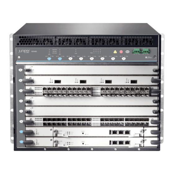
MX480 Craft Interface Description | 36 Alarm Relay Contacts on the MX480 Craft Interface | 37 Alarm LEDs and Alarm Cutoff/Lamp Test Button on the MX480 Craft Interface | 37 MX480 Component LEDs on the Craft Interface | 38 MX480 Cable Management Brackets | 41... - Page 30 Figure 1: Front View of a Fully Configured Router Chassis ESD point Craft interface panel Front-mounting flange DPC5 DPC4 DPC3 DPC2 DPC1 DPC0 SCB1 SCB0 Air intake Figure 2: Rear View of a Fully Configured AC-Powered Router Chassis...
-
Page 31: Mx480 Component Redundancy
Figure 3: Rear View of a Fully Configured DC-Powered Router Chassis SEE ALSO MX480 Router Physical Specifications | 178 MX480 Component Redundancy A fully configured router is designed so that no single point of failure can cause the entire system to fail. -
Page 32: Mx480 Router Hardware And Cli Terminology Mapping
MX480 Router Hardware and CLI Terminology Mapping The MX480 router supports the components in Table 5 on page Table 5: MX480 Router Hardware Components and CLI Terminology Component Hardware Model Number CLI Name... - Page 33 Table 5: MX480 Router Hardware Components and CLI Terminology (continued) Component Hardware Model Number CLI Name Description Cooling System Fan tray FFANTRAY-MX480 Left Fan tray “MX480 Cooling System Description” on page 43 High-capacity fan tray FFANTRAY-MX480-HC Enhanced Left Fan Tray...
- Page 34 Table 5: MX480 Router Hardware Components and CLI Terminology (continued) Component Hardware Model Number CLI Name Description “MPCs Supported by MX Series Routers” “MX480 Modular Port Concentrator (MPC) on page 154 in the MX Series Interface Module Description” on page 151 Reference.
-
Page 35: Mx480 Craft Interface Description
Table 5: MX480 Router Hardware Components and CLI Terminology (continued) Component Hardware Model Number CLI Name Description Power supply blank PWR-BLANK-MX480 “MX480 Power System Description” on panel page 45 SEE ALSO MX480 DPC Port and Interface Numbering | 112 MX480 MIC Port and Interface Numbering | 137... -
Page 36: Alarm Relay Contacts On The Mx480 Craft Interface
Figure 5: Alarm Relay Contacts Alarm LEDs and Alarm Cutoff/Lamp Test Button on the MX480 Craft Interface Two large alarm LEDs are located at the upper right of the craft interface. The circular red LED lights to indicate a critical condition that can result in a system shutdown. -
Page 37: Mx480 Component Leds On The Craft Interface
Host Subsystem LEDs on the MX480 Craft Interface | 38 Power Supply LEDs on the MX480 Craft Interface | 39 DPC and MPC LEDs on the MX480 Craft Interface | 39 FPC LEDs on the MX480 Craft Interface | 40... -
Page 38: Power Supply Leds On The Mx480 Craft Interface
Power supply has failed or power input has failed. steadily DPC and MPC LEDs on the MX480 Craft Interface Each DPC or MPC has LEDs on the craft interface that indicate its status. The LEDs, labeled 0 through 5, are located along the bottom of the craft interface. -
Page 39: Fpc Leds On The Mx480 Craft Interface
Card has failed. steadily FPC LEDs on the MX480 Craft Interface An FPC takes up two DPC slots when installed in an MX Series router. The LEDs, labeled 0 through 5, are located along the bottom of the craft interface. The LED corresponds to the lowest DPC slot number in which the FPC is installed. -
Page 40: Fan Leds On The Mx480 Craft Interface
The slot is not online. FAIL SCB has failed. steadily Fan LEDs on the MX480 Craft Interface The fan LEDs are located on the top left of the craft interface. Table 12 on page 41 describes the functions of the fan LEDs. - Page 41 Figure 6: Cable Management Brackets Figure 7: Cable Management Brackets Installed on the Router SEE ALSO Maintaining Cables That Connect to MX480 DPCs, MPCs, MICs, or PICs | 384 Replacing the MX480 Cable Management Brackets | 286...
-
Page 42: Mx480 Cooling System
MX480 Cooling System IN THIS SECTION MX480 Cooling System Description | 43 MX480 Fan LED | 45 MX480 Cooling System Description The cooling system consists of the following components: Fan tray Air filter The cooling system components work together to keep all router components within the acceptable... - Page 43 The host subsystem monitors the temperature of the router components. When the router is operating normally, the fans function at lower than full speed. If a fan fails or the ambient temperature rises above a threshold, the speed of the remaining fans is automatically adjusted to keep the temperature within the acceptable range.
-
Page 44: Mx480 Fan Led
MX480 Power System Description The MX480 router uses either AC or DC power supplies. The MX480 router is configurable with two, three, or four AC power supplies or two or four DC power supplies. The power supplies connect to the midplane, which distributes the different output voltages produced by the power supplies to the router components, depending on their voltage requirements. -
Page 45: Mx480 Ac Power System
RELATED DOCUMENTATION Connecting Power to an AC-Powered MX480 Router with Normal-Capacity Power Supplies | 254 Connecting Power to a DC-Powered MX480 Router with Normal Capacity Power Supplies | 257 Replacing an MX480 AC Power Supply | 392 MX480 Chassis Grounding Specifications | 182... - Page 46 For high-capacity power supplies, each inlet requires a dedicated AC power feed and a dedicated 16.0 A @ 100 VAC or 16.0 A @ 200 VAC circuit breaker, or as required by local code. The maximum inrush current for a high-capacity AC power supply is 49A at 264VAC. Figure 11: AC Power Supply Figure 12: High-Capacity AC Power Supply WARNING:...
-
Page 47: Ac Power Supply Configurations
AC Power Supply Configurations The MX480 high-capacity and normal-capacity power supplies each support either of the following AC power configurations: In the low-line (110 V) AC power configuration, the MX480 router contains three or four AC power supplies (see Figure 11 on page 47), located horizontally at the rear of the chassis in slots PEM0 through PEM3 (left to right). -
Page 48: Ac Electrical Specifications For The Mx480 Router
Power supply is not functioning normally and its output voltage is out of regulation limits. Check AC OK and DC OK LEDs for more information. AC Electrical Specifications for the MX480 Router Table 14 on page 49 lists the AC power supply electrical specifications;... - Page 49 Table 14: AC Power Supply Electrical Specifications (continued) Item Specification Efficiency 85% (low line and high line) NOTE: This value is at full load and nominal voltage. High-Capacity Power Supplies Maximum output power 1167 W (low line) 2050 W (high line) AC input voltage Operating range: 100 –...
-
Page 50: Ac Power Circuit Breaker Requirements For The Mx480 Router
Calculating Power Requirements for MX480 Routers | 199 AC Power Circuit Breaker Requirements for the MX480 Router Each AC power supply has a single AC appliance inlet located on the power supply that requires a dedicated AC power feed. We recommend that you use a customer site circuit breaker rated for 15 A (250 VAC) minimum for each AC power supply, or as required by local code. - Page 51 Table 16: AC Power Cord Specifications (continued) Electrical Country Model Number Specification Plug Type Japan CBL-PWR-RA-JP15 125 VAC, 50 or 60 Hz JIS 8303 CBL-M-PWR-RA-JP 220 VAC, 50 or 60 Hz NEMA L6-20P North America CBL-PWR-RA-US15 125 VAC, 60 Hz AC NEMA 5-15P CBL-PWR-RA-TWLK-US15 125 VAC, 60 Hz AC...
- Page 52 Power cords and cables must not block access to device components or drape where people could trip on them. SEE ALSO Connecting Power to an AC-Powered MX480 Router with Normal-Capacity Power Supplies | 254 Replacing an MX480 AC Power Supply Cord | 395...
-
Page 53: Outstanding Issues With The Mx480 Router
You need to insert the optics and fiber firmly until the latch is securely in place. [PR/98055] Do not mix AC and DC power supplies on an MX480 router. Mixing of AC supplies and DC supplies may damage your chassis. [PR/233340]... -
Page 54: Errata With The Mx480 Router Documentation
Two threaded inserts (PEM nuts) are provided on the upper rear of the chassis for connecting the router to earth ground. The grounding points fit UNC 1/4–20 screws (American). The mounting shelf should be installed on the back of the rail as described in the MX480 Universal Routing Platform Hardware Guide. -
Page 55: Mx480 Dc Power System
MX480 DC Power Supply Description | 56 MX480 DC Power Supply LEDs | 58 DC Power Supply Electrical Specifications for the MX480 Router | 58 DC Power Circuit Breaker Requirements for the MX480 Router | 60 DC Power Source Cabling for the MX480 Router | 60... -
Page 56: Dc Power Supply Configurations
Figure 15: High-Capacity DC Power Supply DC Power Supply Configurations In the DC power configuration, the MX480 router contains either two or four DC power supplies (see Figure 14 on page 56) located at the rear of the chassis in slots PEM0 through PEM3 (left to right). You can upgrade your DC power system from two to four power supplies. -
Page 57: Mx480 Dc Power Supply Leds
Yellow DC input is present, but not in valid operating range or connected in reverse polarity. DC Power Supply Electrical Specifications for the MX480 Router Table 20 on page 59 lists the DC power supply electrical specifications. Table 21 on page 60 lists the DC power system specifications. - Page 58 Table 20: Power Supply Electrical Specifications Item Specification Normal-Capacity Power Supplies Maximum output power 1600 W DC input current rating 33.3 A @ –48 V nominal operating voltage Maximum Input Current 40 A DC input voltage Operating Range: –40.5 VDC to –72 VDC Nominal: –48 VDC Efficiency ~98%...
-
Page 59: Dc Power Circuit Breaker Requirements For The Mx480 Router
SEE ALSO Calculating Power Requirements for MX480 Routers | 199 DC Power Circuit Breaker Requirements for the MX480 Router Each DC power supply has a single DC input (–48 VDC and return) that requires a dedicated circuit breaker. If you plan to operate a maximally configured DC-powered router with normal-capacity power supplies, we recommend that you use a dedicated customer site circuit breaker rated for 40 A (–48 VDC) minimum,... - Page 60 Power cords and cables must not block access to device components or drape where people could trip on them. SEE ALSO In Case of an Electrical Accident Connecting Power to a DC-Powered MX480 Router with Normal Capacity Power Supplies | 257 Replacing an MX480 DC Power Supply Cable | 402...
-
Page 61: Dc Power Cable Specifications For The Mx480 Router
DC Power Cable Specifications for the MX480 Router DC Power Cable Lug Specifications—The accessory box shipped with the router includes the cable lugs that attach to the terminal studs of each power supply (see Figure 17 on page 62). Figure 17: DC Power Cable Lug 2.25... -
Page 62: Mx480 Host Subsystem
0. Each host subsystem has three LEDs that display its status. The host subsystem LEDs are located in the middle of the craft interface. SEE ALSO Maintaining the MX480 Host Subsystem | 297... -
Page 63: Mx480 Host Subsystem Leds
Each host subsystem has three LEDs that display its status. The host subsystem LEDs are located on the upper left of the craft interface. For more information, see “Host Subsystem LEDs on the MX480 Craft Interface” on page MX480 Midplane Description... -
Page 64: Mx480 Routing Engine Description
SEE ALSO MX480 Router Description | 27 MX480 Chassis Description | 30 MX480 Dense Port Concentrator (DPC) Description | 109 MX480 Modular Port Concentrator (MPC) Description | 151 MX-Series Switch Control Board (SCB) Description | 170 MX480 Flexible PIC Concentrator (FPC) Description | 119... - Page 65 The Routing Engine is an Intel-based PC platform that runs Junos OS. Software processes that run on the Routing Engine maintain the routing tables, manage the routing protocols used on the router, control the router interfaces, control some chassis components, and provide the interface for system management and user access to the router.
-
Page 66: Routing Engine Components
Figure 21: RE-S-X6-64G-LT Routing Engine Front View Extractor clips ONLINE/OFFLINE Button — — Auxiliary port (AUX) SSD LEDs—DISK1 and DISK2 — — Console port (Con) Ports—USB1 and USB2 — — Management port (MGMT) RESET Button — — LEDs—ONLINE, OK/FAIL, and MASTER SSD card slot cover —... -
Page 67: Routing Engine Boot Sequence
If two Routing Engines are installed, they must both be the same hardware model. SEE ALSO MX480 Router Description | 27 MX480 Routing Engine LEDs | 68 MX480 Host Subsystem Description | 63 MX-Series Switch Control Board (SCB) Description | 170 MX480 Routing Engine LEDs Each Routing Engine has four LEDs that indicate its status. - Page 68 Figure 22: RE-S-1800 Routing Engine Table 23: RE-S-1800 Routing Engine LEDs Label Color State Description MASTER Blue Routing Engine is the Master. steadily Green Blinking Indicates activity on the hard disk drive. ONLINE Green Blinking Routing Engine is transitioning online. Routing Engine is functioning normally.
-
Page 69: Routing Engine Leds (Re-S-X6-64G)
Routing Engine LEDs (RE-S-X6-64G) Figure 23: RE-S-X6-64G Routing Engine LEDs ONLINE LED DISK2 LED — — OK/FAIL LED ONLINE/OFFLINE Button — — DISK1 LED MASTER LED — — Table 24: Routing Engine LEDs (RE-S-X6-64G) Label Color State Description ONLINE Green Blinking slowly Routing Engine is in the process of booting BIOS, and the host OS. -
Page 70: Re-S-1800 Routing Engine Description
Replacing an MX480 Routing Engine | 300 RE-S-1800 Routing Engine Description IN THIS SECTION RE-S-1800 Routing Engine Components | 71 RE-S-1800 Routing Engine LEDs | 72 RE-S-1800 Routing Engine Boot Sequence | 73 Figure 24 on page 71 shows RE-S-1800 routing engine. - Page 71 Interface ports—The AUX, CONSOLE, and ETHERNET provide access to management devices. Each Routing Engine has one 10/100/1000-Mbps Ethernet port for connecting to a management network, and two asynchronous serial ports—one for connecting to a console and one for connecting to a modem or other auxiliary device.
-
Page 72: Re-S-1800 Routing Engine Leds
RE-S-1800 Routing Engine Boot Sequence The router is shipped with Junos OS preinstalled on the Routing Engine. There are three copies of software: One copy on the CompactFlash card in the Routing Engine. One copy on the hard disk in the Routing Engine. One copy on a USB flash drive that can be inserted into the slot on the Routing Engine faceplate. -
Page 73: Re-S-X6-64G Routing Engine Description
OK/FAIL Routing Engine has failed. steadily SEE ALSO MX240 Routing Engine Description MX480 Routing Engine Description | 65 MX960 Routing Engine Description RE-S-X6-64G Routing Engine Description IN THIS SECTION RE-S-X6-64G Routing Engine Components | 75 RE-S-X6-64G Routing Engine Boot Sequence | 76... -
Page 74: Re-S-X6-64G Routing Engine Components
Figure 25 on page 75 shows the Routing Engine. Figure 25: RE-S-X6-64G Routing Engine Front View Extractor clips ONLINE/OFFLINE button — — Auxiliary port (AUX) SSD LEDs—DISK1 and DISK2 — — Console port (CONSOLE) Ports—USB1 and USB2 — — Management port (MGMT) RESET button —... -
Page 75: Re-S-X6-64G Routing Engine Boot Sequence
NOTE: The ONLINE/OFFLINE button must be pressed for a minimum of 4 seconds for the power off or power on to occur. Extractor clips—Control the locking system that secures the Routing Engine. LEDs—“RE-S-X6-64G Routing Engine LEDs” on page 76 describes the functions of these LEDs. NOTE: For specific information about Routing Engine components (for example, the amount of DRAM), issue the show vmhost hardware command. - Page 76 Figure 26: RE-S-X6-64G Routing Engine LEDs ONLINE LED DISK2 LED — — OK/FAIL LED ONLINE/OFFLINE button — — DISK1 LED MASTER LED — — Table 27: RE-S-X6-64G Routing Engine LEDs Label Color State Description ONLINE Green Blinking slowly Routing Engine is in the process of booting BIOS, and the host OS.
-
Page 77: Re-S-X6-128G Routing Engine Description
MX240 Routing Engine Description MX960 Routing Engine Description RE-S-X6-128G Routing Engine Description IN THIS SECTION RE-S-X6-128G Routing Engine Components | 78 RE-S-X6-128G Routing Engine LEDs | 79 RE-S-X6-128G Routing Engine Boot Sequence | 81 Figure 27 on page 78 shows the Routing Engine. Figure 27: RE-S-X6-128G Routing Engine Front View Extractor clips ONLINE/OFFLINE button... -
Page 78: Re-S-X6-128G Routing Engine Leds
DRAM—Provides storage for the routing and forwarding tables and for other Routing Engine processes. One 10-Gigabit Ethernet interface between the Routing Engine and Switch Control Board. Two 50-GB slim solid-state drives—SSD1 (primary) and SSD2 (secondary)—Provide storage for software images, configuration files, microcode, log files, and memory dumps. The Routing Engine reboots from SSD2 when boot from primary SSD fails. - Page 79 Figure 28: RE-S-X6-128G Routing Engine LEDs ONLINE LED DISK2 LED — — OK/FAIL LED ONLINE/OFFLINE button — — DISK1 LED MASTER LED — — Table 28: RE-S-X6-128G Routing Engine LEDs Label Color State Description ONLINE Green Blinking slowly Routing Engine is in the process of booting BIOS, and the host OS.
-
Page 80: Re-S-X6-128G Routing Engine Boot Sequence
RE-S-X6-128G Routing Engine Boot Sequence Booting in a RE-S-X6-128G Routing Engine follows this sequence—the USB device, SSD1, SSD2, LAN. SSD1 is the primary boot device. The boot sequence is tried twice for SSD1 and SSD2. SEE ALSO Supported Routing Engines by Router | 89 Routing Engine Specifications | 81 Routing Engine Specifications Table 29 on page 81... - Page 81 Table 29: Routing Engine Specifications (continued) First Switch Connection Junos OS Control Routing Engine Processor Memory to PFEs Disk Media Support Board RE-A-2000-4096 2.0-GHz 4096 MB Gigabit 40 GB 1 GB – Pentium Ethernet hard CompactFlash disk card RE-S-1300-2048 1.3-GHz 2048 MB Gigabit 40 GB...
- Page 82 Table 29: Routing Engine Specifications (continued) First Switch Connection Junos OS Control Routing Engine Processor Memory to PFEs Disk Media Support Board RE-C1800 1.8-GHz 8 GB Gigabit 4 GB T1600 CB-T for a Ethernet CompactFlash router in a standalone card routing router.
- Page 83 Table 29: Routing Engine Specifications (continued) First Switch Connection Junos OS Control Routing Engine Processor Memory to PFEs Disk Media Support Board RE-C2600 2.6-GHz 16 GB Gigabit 4 GB TX Matrix – Ethernet CompactFlash Plus router: card 9.6R2 RE-A-1800x2 1800-MHz 8 GB or Gigabit 32 GB...
- Page 84 Table 29: Routing Engine Specifications (continued) First Switch Connection Junos OS Control Routing Engine Processor Memory to PFEs Disk Media Support Board RE-S-X6-64G, 2 Ghz 64 GB Gigabit 15.1F4, SCBE2, RE-S-X6-64G-LT Ethernet 50-GB 16.1 SCBE3 SSDs REMX2K-X8-64G 2.3 Ghz 64 GB Gigabit 15.1F5-S1, –...
- Page 85 Table 30: Hardware Specifications of the RE-MX-X6, RE-MX-X8, RE-PTX-X8, RCBPTX, RE-QFX10002-60C, and RE-PTX10002-60C Routing Engines Model Number Supported on Device Specifications RE-S-X6-64G MX240, MX480, and 6-core Haswell CPU MX960 Wellsburg PCH-based Routing Engine with 64-GB DRAM and two 64-GB solid-state drives (SSDs)
- Page 86 Table 30: Hardware Specifications of the RE-MX-X6, RE-MX-X8, RE-PTX-X8, RCBPTX, RE-QFX10002-60C, and RE-PTX10002-60C Routing Engines (continued) Model Number Supported on Device Specifications REMX2K-X8-64G MX2020 and MX2010 8-core Haswell CPU Wellsburg PCH-based Routing Engine with 64-GB DRAM and two 64-GB SSDs RE-PTX-X8-64G PTX5000 8-core Haswell CPU...
- Page 87 Table 31: End-of-Life Routing Engine Specifications Routing Connection First Junos Engine Processor Memory to PFEs Disk Media OS Support EOL Details RE-333-256 333-MHz 256 MB Fast 6.4 GB 80 MB PSN-2003-01-063 Pentium II Ethernet hard disk CompactFlash card RE-333-768 333-MHz 768 MB Fast 6.4 GB...
-
Page 88: Supported Routing Engines By Router
MX5, MX10, MX40, and MX80 Routing Engine | 93 MX104 Routing Engines | 93 MX204 Routing Engine | 94 MX240 Routing Engines | 94 MX480 Routing Engines | 95 MX960 Routing Engines | 97 MX2008 Routing Engines | 98 MX2010 Routing Engines | 98... -
Page 89: M7I Routing Engines
T4000 Routing Engines | 106 TX Matrix Routing Engines | 107 TX Matrix Plus Routing Engines | 108 TX Matrix Plus (with 3D SIBs) Routing Engines | 108 The following tables list the Routing Engines that each router supports, the first supported release for the Routing Engine in the specified router, the management Ethernet interface, and the internal Ethernet interfaces for each Routing Engine. -
Page 90: M40E Routing Engines
Table 33: M10i Routing Engines First Supported Management Name in CLI 32-bit Junos OS Ethernet Internal Ethernet Model Number Output Release Interface Interface RE-400-768 (EOL details: RE-5.0 fxp0 fxp1 TSB16445) fxp2 RE-850-1536 (EOL details: RE-850 fxp0 fxp1 TSB15553) fxp2 RE-B-1800X1-4G RE-B-1800x1 11.4R4 fxp0... -
Page 91: M320 Routing Engines
Table 35: M120 Routing Engines First First Supported Supported Management Internal Name in CLI 32-bit Junos OS 64-bit Junos Ethernet Ethernet Model Number Output Release OS Release Interface Interface RE-A-1000-2048 RE-A-1000 8.0R2 – fxp0 fxp1 fxp2 RE-A-2000-4096 RE-A-2000 8.0R2 – fxp0 bcm0 RE-A-1800X2-8G... -
Page 92: Mx5, Mx10, Mx40, And Mx80 Routing Engine
Table 36: M320 Routing Engines (continued) First First Supported Supported Management Internal Name in CLI 32-bit Junos OS 64-bit Junos Ethernet Ethernet Model Number Output Release OS Release Interface Interface RE-A-1800X2-8G RE-A-1800x2 11.4R5 10.4 fxp0 12.1R3 bcm0 RE-A-1800X2-16G RE-A-1800x2 11.4R5 10.4 fxp0 12.1R3... -
Page 93: Mx204 Routing Engine
Table 38: MX104 Routing Engines First Supported First Supported Management Internal Model Name in CLI 32-bit Junos OS 64-bit Junos OS Ethernet Ethernet Number Output Release Release Interface Interface RE-S-MX104 Routing Engine 13.2 – fxp0 fxp1 fxp2 MX204 Routing Engine Table 39 on page 94 lists the Routing Engines supported by the MX204 router. -
Page 94: Mx480 Routing Engines
13.2R1 13.2R1 RE-S-X6-64G RE-S-2X00x6 – 15.1F4 fxp0 ixlv0, igb0 16.1R1 RE-S-X6-64G-LT RE-S-2X00x6 – 17.2R1 fxp0 ixlv0, igb0 RE-S-X6-128G RE-S-2X00x6-128 – 18.1R1 fxp0 ixlv0, igb0 MX480 Routing Engines Table 41 on page 96 lists the Routing Engines supported by MX480 routers. - Page 95 Table 41: MX480 Supported Routing Engines First Supported First Supported Management Internal Name in CLI 32-bit Junos 64-bit Junos Ethernet Ethernet Model Number Output OS Release OS Release Interface Interface RE-S-1300-2048 RE-S-1300 – fxp0 fxp1 (EOL details: fxp2 TSB16556 RE-S-2000-4096 RE-S-2000 –...
-
Page 96: Mx960 Routing Engines
MX960 Routing Engines Table 42 on page 97 lists the Routing Engines supported by MX960 routers. Table 42: MX960 Supported Routing Engines First First Supported Supported Management Internal Name in CLI 32-bit Junos 64-bit Junos Ethernet Ethernet Model Number Output OS Release OS Release Interface... -
Page 97: Mx2008 Routing Engines
Table 42: MX960 Supported Routing Engines (continued) First First Supported Supported Management Internal Name in CLI 32-bit Junos 64-bit Junos Ethernet Ethernet Model Number Output OS Release OS Release Interface Interface RE-S-X6-128G RE-S-2X00x6-128 – 18.1R1 fxp0 ixlv0, igb0 MX2008 Routing Engines Table 43 on page 98 lists the Routing Engines supported by MX2008 routers. -
Page 98: Mx2020 Supported Routing Engines
Table 44: MX2010 Supported Routing Engines (continued) Management Internal Name in CLI First Supported 64-bit Ethernet Ethernet Model Number Output Junos OS Release Interface Interface REMX2K-1800-32G-S RE-S-1800x4 12.3R4 fxp0 13.2R1 REMX2K-X8-64G RE-S-2X00x8 15.1F5-S1 fxp0 ixlv0 16.1R2 ixlv1 16.2R1 REMX2K-X8-64G-LT RE-S-2X00x8 17.2R1 fxp0 ixlv0... -
Page 99: Mx10003 Routing Engines
Table 45: MX2020 Supported Routing Engines (continued) Management Internal Name in CLI First Supported 64-bit Ethernet Ethernet Model Number Output Junos OS Release Interface Interface REMX2K-X8-64G-LT RE-S-2X00x8 17.2R1 fxp0 ixlv0 ixlv1 REMX2K-X8-128G RE-MX200X8-128G 18.1R1 fxp0 ixlv0 ixlv1 MX10003 Routing Engines Table 46 on page 100 lists the Routing Engines supported by MX10003 routers. -
Page 100: Ptx1000 Routing Engines
Table 47: MX10008 Routing Engines Name in CLI First Supported Management Internal Ethernet Model Number Output Junos OS Release Ethernet Interface Interface JNP10K-RE1 RE X10 18.2R1 bme0 bme1 PTX1000 Routing Engines Table 48 on page 101 lists the Routing Engine supported on the PTX1000. NOTE: The PTX1000 supports 64-bit Junos OS only. -
Page 101: Ptx5000 Routing Engines
Table 49: PTX3000 Routing Engines (continued) Management Name in CLI First Supported Junos OS Ethernet Internal Ethernet Model Number Output Release Interface Interface RCB-PTX-X6-32G RE-PTX-2X00x6 16.1R4 ixlv0 17.1R1 ixlv1 This Routing Engine does not support Junos OS Release 16.2. PTX5000 Routing Engines Table 50 on page 102 lists the Routing Engines supported on the PTX5000. -
Page 102: Ptx10008 And Ptx10016 Routing Engines
Table 50: PTX5000 Routing Engines (continued) Management Internal First Supported Junos Ethernet Ethernet Model Number Name in CLI Output OS Release Interface Interface RE-PTX-X8-64G RE-PTX-2X00x8 15.1F4 ixlv0 16.1R1 ixlv1 RE-PTX-X8-128G RE-PTX-2X00x8-128G 18.1R1 ixlv0 ixlv1 PTX10008 and PTX10016 Routing Engines Table 51 on page 103 lists the Routing Engines supported on the PTX10008 and PTX10016 routers. -
Page 103: T640 Routing Engines
Table 52: T320 Routing Engines First Supported Management Name in CLI 32-bit Junos OS Ethernet Internal Ethernet Model Number Output Release Interface Interface RE-600-2048 (EOL details: RE-3.0 or RE-3.0 fxp0 fxp1 TSB14373) (RE-600) fxp2 RE-1600-2048 (EOL details: RE-4.0 fxp0 fxp1 TSB14374 fxp2 RE-A-2000-4096... -
Page 104: T1600 Routing Engines
Table 53: T640 Routing Engines (continued) First Supported First Supported Management Internal Name in CLI 32-bit Junos OS 64-bit Junos OS Ethernet Ethernet Model Number Output Release Release Interface Interface RE-DUO-C1800-8G RE-DUO-1800 32-bit Junos OS on 64-bit Junos OS on bcm0 a standalone T640 a standalone T640... -
Page 105: T4000 Routing Engines
Table 54: T1600 Routing Engines (continued) First Supported First Supported Management Internal Name in CLI 32-bit Junos OS 64-bit Junos OS Ethernet Ethernet Model Number Output Release Release Interface Interface RE-1600-2048 (EOL RE-4.0 – fxp0 fxp1 details: TSB14374 (RE-1600) fxp2 RE-A-2000-4096 RE-A-2000 –... -
Page 106: Tx Matrix Routing Engines
NOTE: The T4000 router supports 64-bit Junos OS only. Table 55: T4000 Routing Engines Management Internal Name in CLI First Supported 64-bit Junos Ethernet Ethernet Model Number Output OS Release Interface Interface RE-DUO-C1800-8G RE-DUO-1800 Standalone T4000 router: 12.1 bcm0 T4000 router in a routing matrix: 13.1 RE-DUO-C1800-16G RE-DUO-1800... -
Page 107: Tx Matrix Plus Routing Engines
Table 56: TX Matrix Routing Engines (continued) First First Supported Supported Management Internal Name in CLI 32-bit Junos 64-bit Junos Ethernet Ethernet Model Number Output OS Release OS Release Interface Interface RE-DUO-C1800-8G RE-DUO-1800 11.4R9 11.4R9 bcm0 RE-DUO-C1800-16G RE-DUO-1800 11.4R9 11.4R9 bcm0 The TXP router supports two control boards, CB-TX and CB-LCC. -
Page 108: Mx480 Interface Modules-Dpcs
MX480 DPC Port and Interface Numbering | 112 MX480 Dense Port Concentrator (DPC) LEDs | 115 DPCs Supported on MX240, MX480, and MX960 Routers | 116 MX480 Dense Port Concentrator (DPC) Description A Dense Port Concentrator (DPC) is optimized for Ethernet density (see Figure 29 on page 110). - Page 109 DPC runs its diagnostics, and the Packet Forwarding Engines housed on the DPC are enabled. Forwarding on other DPCs continues uninterrupted during this process. Figure 29 on page 110 shows typical DPCs supported on the MX480 router. For more information about DPCs, see the MX Series Interface Module Reference.
-
Page 110: Dpc Components
MX Series Interface Module Reference. Two LEDs, located on the craft interface above the DPC, display the status of the DPC and are labeled OK and FAIL. SEE ALSO DPC and MPC LEDs on the MX480 Craft Interface | 39... -
Page 111: Mx480 Dpc Port And Interface Numbering
Ethernet interface For a complete list of media types, see Interface Naming Overview. fpc—Slot in which the DPC is installed. On the MX480 router, the DPCs are represented in the CLI as FPC 0 through FPC 5. pic—Logical PIC on the DPC. The number of logical PICs varies depending on the type of DPC. For example, a: 20-port Gigabit Ethernet DPC has two logical PICs, numbered 0 through 1. - Page 112 Figure 31: MX480 DPC Interface Port Mapping DPCE-R-40GE-SFP ge-3/2/0 ge-3/2/5 ge-3/3/0 ge-3/3/5 3/2/2 3/2/4 3/2/7 3/2/9 3/3/2 3/3/4 3/3/7 3/3/9 3/2/1 3/2/3 3/2/6 3/2/8 3/3/1 3/3/3 3/3/6 3/3/8 3/0/1 3/0/3 3/0/6 3/0/8 3/1/1 3/1/3 3/1/6 3/1/8 3/0/2 3/0/4 3/0/7 3/0/9...
- Page 113 Xcvr 0 REV 01 740-011782 PCH2UYF SFP-SX Xcvr 1 REV 01 740-011782 PCH2P4L SFP-SX Xcvr 2 REV 01 740-011782 PCH2UCL SFP-SX Xcvr 3 REV 01 740-011782 PCH2P4X SFP-SX Xcvr 4 REV 01 740-011782 PCH2P1E SFP-SX Xcvr 5 REV 01 740-011782 PCH2UD2 SFP-SX Xcvr 6...
-
Page 114: Mx480 Dense Port Concentrator (Dpc) Leds
SEE ALSO MX480 Router Hardware and CLI Terminology Mapping | 33 MX480 Dense Port Concentrator (DPC) LEDs Two LEDs, located on the craft interface above the DPC, display the status of the DPC and are labeled OK and FAIL. For more information about the DPC LEDs on the craft interface, see “DPC and MPC LEDs... -
Page 115: Dpcs Supported On Mx240, Mx480, And Mx960 Routers
These DPCs have all been announced as End of Life (EOL). The End of Support (EOS) milestone dates for each model are published at https://www.juniper.net/support/eol/mseries_hw.html. Table 59 on page 116 lists the DPCs supported by the MX240, MX480, and MX960 routers. Table 59: DPCs Supported in MX240, MX480, and MX960 Routers Maximum First... - Page 116 Table 59: DPCs Supported in MX240, MX480, and MX960 Routers (continued) Maximum First DPC Model Throughput Junos OS DPC Name Number Ports per DPC Release Gigabit Ethernet Enhanced Queuing Ethernet Services DPCE-X-Q-40GE-SFP 40 Gbps DPC with SFP EOL (see PSN-2013-02-851)
- Page 117 Table 59: DPCs Supported in MX240, MX480, and MX960 Routers (continued) Maximum First DPC Model Throughput Junos OS DPC Name Number Ports per DPC Release 10-Gigabit Ethernet Enhanced Queuing IP Services DPC DPCE-R-Q-4XGE-XFP 40 Gbps with XFP EOL (see PSN-2011-02-314)
-
Page 118: Mx480 Interface Modules-Fpcs And Pics
IN THIS SECTION MX480 Flexible PIC Concentrator (FPC) Description | 119 MX480 Flexible PIC Concentrator (FPC) LEDs | 121 FPCs Supported by MX240, MX480, and MX960 Routers | 122 MX480 PIC Description | 122 MX480 PIC Port and Interface Numbering | 123... - Page 119 Figure 32: FPC Installed in the MX480 Router Chassis M X4 80 Figure 33 on page 120 shows the typical FPCs supported on the MX480 router. Figure 33: Typical FPCs Supported on the MX480 Router MX-FPC2 FPC3 If a slot is not occupied by a DPC, an FPC, or an SCB, a blank panel must be installed to shield the empty slot and to allow cooling air to circulate properly through the router.
-
Page 120: Fpc Components
SEE ALSO Maintaining MX480 FPCs | 338 MX480 FPC Terminology Troubleshooting the MX480 FPCs | 440 Replacing an MX480 FPC | 345 MX480 Flexible PIC Concentrator (FPC) LEDs Two LEDs, located on the craft interface above the FPC, that display the status of the FPC and are labeled OK and FAIL. -
Page 121: Fpcs Supported By Mx240, Mx480, And Mx960 Routers
PICs are hot-removable and hot-insertable. Up to two PICs can be installed in the slots in each FPC. Up to three FPCs can be installed in an MX480 router. PICs used in a Type 2 FPC have captive screws at their... -
Page 122: Mx480 Pic Port And Interface Numbering
For a complete list of media types, see Interface Naming Overview. fpc—Lowest slot number in which the FPC is installed. On the MX480 router, FPCs occupy two line card slots and are represented in the CLI as FPC 0 through FPC 4. - Page 123 Figure 34: MX480 PIC Interface Port Mapping The show chassis hardware command output displays a Channelized OC12/STM4 Enhanced IQ (IQE) PIC (4x CHOC12 IQE SONET) installed in MX FPC Type 2. user@host> show chassis hardware FPC 3 REV 01 710-024386...
-
Page 124: Mx480 Pic Leds
Maintaining MX480 PICs | 368 PICs Supported by MX240, MX480, and MX960 Routers Table 61 on page 125 lists the PICs supported by MX240, MX480, and MX960 routers. Table 61: PICs Supported by MX240, MX480, and MX960 Routers PIC Name... - Page 125 Table 61: PICs Supported by MX240, MX480, and MX960 Routers (continued) PIC Name PIC Model Number Ports Type First Junos OS Release Channelized OC12/STM4 Enhanced PB-4CHOC12-STM4-IQE-SFP IQ (IQE) PIC with SFP Channelized OC48/STM16 PB-1CHOC48-STM16-IQE Enhanced IQ (IQE) PIC with SFP...
-
Page 126: Mx480 Interface Modules-Mpcs And Mics
The following tables provide a compatibility matrix for the MICs currently supported by MPC1, MPC2, MPC3, MPC6, MPC8, and MPC9 on MX240, MX480, MX960, MX2008, MX2010, MX2020, and MX10003 routers. Each table lists the first Junos OS release in which the MPC supports the MIC. For example, Junos OS Release 10.2 is the first release in which the MX-MPC1-3D supports the Gigabit Ethernet MIC with... - Page 127 Table 62: MIC/MPC1 Compatibility (continued) MIC Name MPC1 MPC1E MPC1 Q MPC1E Q MIC-3D-20GE-SFP 10.2 11.2R4 10.2 11.2R4 (Gigabit Ethernet MIC with SFP) MIC-3D-20GE-SFP-E 13.2R2 13.2R2 13.2R2 13.2R2 (Gigabit Ethernet MIC with SFP (E)) MIC-3D-2XGE-XFP 10.2 11.2R4 10.2 11.2R4 (10-Gigabit Ethernet MICs with XFP) MIC-3D-4XGE-XFP —...
- Page 128 Table 62: MIC/MPC1 Compatibility (continued) MIC Name MPC1 MPC1E MPC1 Q MPC1E Q M I C - 3 D - 4 C H O C 3 - 2 C H O C 1 2 , — — 11.4 11.4 MI C -3D-8CHOC3-4CHOC12 MIC-4COC3-2COC12-G, MIC-8COC3-4COC12-G (Channelized...
- Page 129 Table 63: MIC/MPC2 Compatibility MPC2E MPC2 MPC2E MPC2 MPC2E MPC2E MPC2E MIC Name MPC2 MPC2E NG Q MIC-3D-8OC3-2OC12-ATM — — 14.1R4, 12.1 12.1R4 12.1 12.1R4 — 14.1R4, 14.2R3 14.2R3 (ATM MIC with SFP) with Junos with Junos Continuity Continuity 15.1 15.1 MIC-3D-20GE-SFP 10.1...
- Page 130 Table 63: MIC/MPC2 Compatibility (continued) MPC2E MPC2 MPC2E MPC2 MPC2E MPC2E MPC2E MIC Name MPC2 MPC2E NG Q MIC-3D-4OC3OC12-1OC48, 11.4 11.4 14.1R4, 11.4 11.4 11.4 11.4 14.1R4, MIC-3D-8OC3OC12-4OC48 14.2R3 14.2R3 with Junos with Junos (SONET/SDH OC3/STM1 Continuity Continuity (Multi-Rate) MICs with SFP) 15.1 15.1 MIC-3D-4COC3-1COC12-CE...
- Page 131 Table 63: MIC/MPC2 Compatibility (continued) MPC2E MPC2 MPC2E MPC2 MPC2E MPC2E MPC2E MIC Name MPC2 MPC2E NG Q MIC-3D-8DS3-E3, 11.4 11.4 14.1R4, 11.4 11.4 11.4 11.4 12.2 14.1R4, MIC-3D-8CHDS3-E3-B 14.2R3 14.2R3 with Junos with Junos (DS3/E3 MIC) Continuity Continuity NOTE: You cannot run 15.1 15.1...
- Page 132 Table 64: MIC/MPC3 Compatibility (continued) MIC Name MPC3E MPC3E NG MPC3E NG Q MIC3-3D-1X100GE-CFP 12.1 14.1R4, 14.2R3 with Junos 14.1R4, 14.2R3 with Junos Continuity Continuity (100-Gigabit Ethernet MIC with CFP) 15.1 15.1 MIC-3D-2XGE-XFP 12.2 14.1R4, 14.2R3 with Junos 14.1R4, 14.2R3 with Junos Continuity Continuity (10-Gigabit Ethernet MICs with XFP)
- Page 133 Table 64: MIC/MPC3 Compatibility (continued) MIC Name MPC3E MPC3E NG MPC3E NG Q MIC-3D-1OC192-XFP 13.3 14.1R4, 14.2R3 with Junos 14.1R4, 14.2R3 with Junos Continuity Continuity (SONET/SDH OC192/STM64 MIC with XFP) 15.1 15.1 MIC-3D-4COC3-1COC12-CE — — 14.1R4, 14.2R3 with Junos Continuity (Channelized OC3/STM1 (Multi-Rate) Circuit Emulation MIC with SFP) 15.1...
- Page 134 Table 64: MIC/MPC3 Compatibility (continued) MIC Name MPC3E MPC3E NG MPC3E NG Q MIC-3D-8DS3-E3, MIC-3D-8CHDS3-E3-B 12.1 14.1R4, 14.2R3 with Junos 14.1R4, 14.2R3 with Junos DS3/E3 MIC Continuity Continuity NOTE: You cannot run Channelized DS3 15.1 15.1 (MIC-3D-8CHDS3-E3) on non-Q MPCs. Channelized DS3 is supported only on Q and EQ-based MPCs.
-
Page 135: Mx480 Modular Interface Card (Mic) Description
MICs Supported by MX Series Routers | 141 Junos Continuity Software User Guide (Junos OS Release 14.1R4 and Later Releases) MX480 Modular Interface Card (MIC) Description Modular Interface Cards (MICs) install into Modular Port Concentrators (MPCs) and provide the physical connections to various network media types. -
Page 136: Mx480 Mic Port And Interface Numbering
Ethernet interface For a complete list of media types, see Interface Naming Overview. fpc—Slot in which the MPC is installed. On the MX480 router, the MPCs are represented in the CLI as FPC 0 through FPC 5. pic—Logical PIC on the MIC, numbered 0 or 1 when installed in slot 0, and 2 or 3 when installed in slot 1. - Page 137 NOTE: The MIC number is not included in the interface name. The MX480 router supports up to six MPCs that install horizontally and are numbered from bottom to top. Each MPC accepts up to two MICs. Figure 35 on page 138 shows a 20-port Gigabit Ethernet MIC with SFP installed in slot 0of an MPC in slot 3.
- Page 138 The following sample CLI output displays a 20-port Gigabit Ethernet MIC with SFP — 3D 20x 1GE(LAN) SFP — installed in slot 0 of an MPC in slot 3. user@host> show chassis hardware FPC 3 REV 28 750-031090 YH8181 MPC Type 2 3D EQ REV 06 711-030884 YH9437...
-
Page 139: Mx480 Modular Interface Card (Mic) Leds
SEE ALSO MX480 Router Hardware and CLI Terminology Mapping | 33 MX480 Modular Interface Card (MIC) LEDs Each MIC has LEDs located on the faceplate. For more information about LEDs on the MIC faceplate, see the “LEDs” section for each MIC in the MX Series Interface Module Reference. -
Page 140: Mics Supported By Mx Series Routers
The following tables list the first supported Junos OS release for the MX Series. Table 69 on page 141 lists the first supported Junos OS release for MICs on MX240, MX480, MX960, and MX2008 routers. Table 70 on page 144 lists the first supported Junos OS release for MICs on MX2010 and MX2020 routers. - Page 141 Table 69: MICs Supported by MX240, MX480, MX960 and MX2008 Routers (continued) MX240, MX480, and MX2008 MIC Name MIC Model Number Ports MX960 Routers Routers 10-Gigabit Ethernet 10-Gigabit Ethernet MICs with MIC-3D-2XGE-XFP 10.2 15.1F7 10-Gigabit Ethernet MICs with MIC-3D-4XGE-XFP 10.1 15.1F7...
- Page 142 Table 69: MICs Supported by MX240, MX480, MX960 and MX2008 Routers (continued) MX240, MX480, and MX2008 MIC Name MIC Model Number Ports MX960 Routers Routers 100-Gigabit DWDM OTN MIC MIC3-100G-DWDM 15.1F5 15.1F7 with CFP2-ACO 15.1F6 17.1R1 Multi-Rate SONET/SDH OC3/STM1 MIC-3D-4OC3OC12-1OC48 11.2...
- Page 143 Table 69: MICs Supported by MX240, MX480, MX960 and MX2008 Routers (continued) MX240, MX480, and MX2008 MIC Name MIC Model Number Ports MX960 Routers Routers SONET/SDH SONET/SDH OC192/STM64 MIC-3D-1OC192-XFP 12.2 15.1F7 MIC with XFP Table 70: MICs Supported by MX2010 and MX2020 Routers...
- Page 144 Table 70: MICs Supported by MX2010 and MX2020 Routers (continued) MX2010 MX2020 MIC Name MIC Model Number Ports Routers Routers 10-Gigabit Ethernet MIC with MIC3-3D-10XGE-SFPP 12.3 12.3 SFP+ (10 Ports) 10-Gigabit Ethernet MIC with MIC6-10G 13.3R2 13.3R2 SFP+ (24 Ports) 10-Gigabit Ethernet OTN MIC MIC6-10G-OTN 13.3R3...
- Page 145 Table 70: MICs Supported by MX2010 and MX2020 Routers (continued) MX2010 MX2020 MIC Name MIC Model Number Ports Routers Routers Channelized SONET/SDH MIC-3D-4CHOC3-2CHOC12 12.3 12.3 OC3/STM1 (Multi-Rate) MICs with SFP Channelized SONET/SDH MIC-3D-8CHOC3-4CHOC12 12.3 12.3 OC3/STM1 (Multi-Rate) MICs with SFP Channelized OC3/STM1 MIC-3D-4COC3-1COC12-CE 12.3...
- Page 146 Table 71: MICs Supported by MX5, MX10, and MX40 Routers (continued) MIC Name MIC Model Number Ports MX10 MX40 ATM MIC with SFP MIC-3D-8OC3-2OC12-ATM 12.1 12.1 12.1 DS3/E3 DS3/E3 MIC MIC-3D-8DS3-E3, 11.4 11.4 11.4 MIC-3D-8CHDS3-E3-B Circuit Emulation Channelized E1/T1 Circuit MIC-3D-16CHE1-T1-CE 13.2R2 13.2R2...
- Page 147 Table 71: MICs Supported by MX5, MX10, and MX40 Routers (continued) MIC Name MIC Model Number Ports MX10 MX40 Channelized SONET/SDH MIC-3D-8CHOC3-4CHOC12 11.4 11.4 11.4 OC3/STM1 (Multi-Rate) MICs with SFP Channelized OC3/STM1 MIC-3D-4COC3-1COC12-CE 12.2 12.2 12.2 (Multi-Rate) Circuit Emulation MIC with SFP Channelized OC3/STM1 MIC-4COC3-1COC12-CE-H (Multi-Rate) Circuit Emulation...
- Page 148 Table 72: MICs Supported by MX80 and MX104 Routers (continued) MIC Name MIC Model Number Ports MX80 MX104 Channelized E1/T1 Circuit MIC-3D-16CHE1-T1-CE 13.2R2 13.2R2 Emulation MIC Channelized E1/T1 Circuit MIC-3D-16CHE1-T1-CE-H – 13.2R2 Emulation MIC (H) Gigabit Ethernet Gigabit Ethernet MIC with SFP MIC-3D-20GE-SFP 10.2 13.2R2...
- Page 149 Table 72: MICs Supported by MX80 and MX104 Routers (continued) MIC Name MIC Model Number Ports MX80 MX104 Channelized OC3/STM1 MIC-4COC3-1COC12-CE-H 13.2R2 (Multi-Rate) Circuit Emulation MIC with SFP (H) Tri-Rate Tri-Rate MIC MIC-3D-40GE-TX 10.2 13.2R2 Services Multiservices MIC MS-MIC-16G 13.2 13.3R2 Rear slot only.
-
Page 150: Mx480 Modular Port Concentrator (Mpc) Description
The MPCs interface with the power supplies and Switch Control Boards (SCBs). You must install redundant SCBs to support full line-rate. The MX480 router supports up to six MPCs. You must install a high-capacity fan tray to use an MPC. For power requirements, see “Calculating Power Requirements for MX480 Routers”... - Page 151 MPC are enabled. Forwarding on other MPCs continues uninterrupted during this process. Figure 37 on page 152 shows a typical MPC supported on the MX480 router. For more information about MPCs, see the MX Series Interface Module Reference.
-
Page 152: Mpc Components
OK and FAIL. For more information about the line card LEDs on the craft interface, see “DPC and MPC LEDs on the MX480 Craft Interface” on page Each MPC also has LEDs located on the faceplate. For more information about LEDs on the MPC faceplate, see the “LEDs”... -
Page 153: Mpcs Supported By Mx Series Routers
MPCs Supported by MX Series Routers Table 74 on page 154 lists the MPCs and their first supported Junos OS release on MX240, MX480, MX960, MX2008, MX2010, MX2020, and MX10003 routers. Table 74: MPCs Supported by MX240, MX480, MX960, MX2008, MX2010, MX2020, and MX10003 Routers... - Page 154 Table 74: MPCs Supported by MX240, MX480, MX960, MX2008, MX2010, MX2020, and MX10003 Routers (continued) First Junos OS Release First Junos First First First First MX240, Junos OS Junos OS Junos OS Junos OS MX480, Release Release Release Release Release...
- Page 155 Table 74: MPCs Supported by MX240, MX480, MX960, MX2008, MX2010, MX2020, and MX10003 Routers (continued) First Junos OS Release First Junos First First First First MX240, Junos OS Junos OS Junos OS Junos OS MX480, Release Release Release Release Release...
- Page 156 Table 74: MPCs Supported by MX240, MX480, MX960, MX2008, MX2010, MX2020, and MX10003 Routers (continued) First Junos OS Release First Junos First First First First MX240, Junos OS Junos OS Junos OS Junos OS MX480, Release Release Release Release Release...
-
Page 157: Mx480 Application Services Modular Line Card Description
Pathfinder: Hardware Supported by Junos Continuity Software MX480 Application Services Modular Line Card Description The Application Services Modular Line Card (AS MLC) is an X86-based card for MX960, MX480, and MX240 routers to deliver integrated application service solutions. The first application that network... -
Page 158: Mx480 As Mlc Function
Additionally, the AS MLC can serve as the platform for Juniper Networks JunosV App Engine, powering a host of network applications directly embedded into your MX Series 5G Universal Routing Platforms. The AS MLC is modular and decouples CPU and storage in individual field-upgradeable units. The AS MLCs are designed to enable application throughput up to 50 Gbps and a storage capacity of 400 gigabytes (GB) of NAND Flash. -
Page 159: As Mlc Components
Each AS MLC consists of the following components: AS MLC Modular Carrier Card (AS MCC), which fits horizontally in front of the MX480 router, includes two slots for the Application Services Modular Storage Card (AS MSC) and Application Services Modular... -
Page 160: Mx480 Application Services Modular Storage Card Description
For AC power supply: PWR-FAN-MX480-AC-HC-U and PWR-MX480-2520-AC-S For DC power supply: PWR-FAN-MX480-DC-HC-U and PWR-MX480-2520-DC-S Fan tray—FFANTRAY-MX480-HC SEE ALSO Replacing an MX480 AS MLC | 374 Replacing an MX480 AS MSC | 378 Replacing an MX480 AS MXC | 382 MX480 Application Services Modular Storage Card Description Application Services Modular Storage Card (AS MSC) is a NAND Flash––based card that is inserted into... -
Page 161: Mx480 Application Services Modular Processing Card Description
Figure 39: Application Services Modular Storage Card SEE ALSO Replacing an MX480 AS MSC | 378 MX480 Application Services Modular Processing Card Description The Application Services Modular Processing Card (AS MXC) is a pluggable X86-based card that can be inserted into the lower slot of the Application Services Modular Line Card (AS MLC). The AS MXC serves as the processing card for the Junos Content Encore system and contains the two X86, Intel 8-core processors with interface ability greater than 80 Gbps. -
Page 162: Mx480 As Msc Leds
Figure 40: Application Services Modular Processing Card (AS MXC) SEE ALSO Replacing an MX480 AS MXC | 382 MX480 AS MSC LEDs Two LEDs (CPU and AP) indicate the status of the AS MSC and are located on the AS MSC. -
Page 163: Mx480 As Mxc Leds
SEE ALSO Replacing an MX480 AS MSC | 378 MX480 AS MXC LEDs Two LEDs (CPU and AP) indicate the status of the AS MXC and are located on the AS MXC. Table 76 on page 164 describes the functions of the AS MXC LEDs. -
Page 164: Services Processing Card-Mx-Spc3 Services Card
Next Gen Services provide the best of both routing and security features on MX Series routers MX240, MX480, and MX960. All Next Gen Services are provided by the MX-SPC3 Services Card. Next Gen Services provide capabilities for manipulating traffic before it’s delivered to its destination. -
Page 165: Mx-Spc3 Services Card
Protocols and Applications Supported by MX-SPC3 Services Card MX-SPC3 Services Card The MX-SPC3 Services Card is supported on MX240, MX480, and MX960 routers. It provides additional processing power to run the Next Gen Services. It contains two Services Processing Units (SPUs) with 128 GB of memory per SPU. Line cards such as... - Page 166 MX240–Any slot, except the bottom slot 0 which is reserved for SCB/RE. MX480–Any slot, except the bottom slots 0 or 1 which are reserved for SCB/RE. MX960–Any slot, except slot 11, and slots 0 or 1 which are reserved for SCB/RE.
- Page 167 Next Gen Services 6rd Softwires Aggregated Multiservices Interfaces Class of Service Deterministic NAT DNS Request Filtering Dynamic Address-Only Source NAT Global System Logging Inline Static Destination NAT Inline Static Source NAT Inline Twice static NAT Inter-chassis High Availability Overview for NAT, Stateful Firewall, and IDS Flows Intrusion Detection Services IPv4 Connectivity Across IPv6-Only Network Using 464XLAT Network Address Port Translation...
- Page 168 LEDs OK/FAIL LED, one bicolor: Steady green–The SPC is operating normally. Red–The SPC has failed and is not operating normally. Off–The SPC is powered down. STATUS LED, one tricolor for each SPU SPU 0 and SPU 1: Off–The SPU is offline. Blinking Amber–The SPU is initializing.
-
Page 169: Mx-Series Switch Control Board (Scb) Description
48 Packet Forwarding Engines. The routing engine installs directly into the SCB. The number of SCBs supported varies, depending on the MX chassis and the level of redundancy. The MX240 and MX480 require two SCBs for 1+1 redundancy, whereas the MX960 requires three SCBs for 2+1 redundancy. - Page 170 Table 78: Switch Control Board Capacities for MX Series 5G Universal Routing Platforms (Full-Duplex) MX240 Fabric MX480 Fabric MX960 Fabric Description Fabric Bandwidth Per Slot Bandwidth Bandwidth Bandwidth Enhanced MX Switch Up to 1.5 Tbps (non-redundant Up to 6 Tbps...
-
Page 171: Cli Identification
Table 79: Supported Routing Engines for MX Series 5G Universal Routing Platforms Switch Control Boards (continued) Switch Control Board Supported Routing Engines SCBE-MX RE-S-1300 (EOLed) RE-S-2000 (EOLed) RE-S-1800* SCB-MX RE-S-1300 (EOLed) RE-S-2000 (EOLed) RE-S-1800 * All variants CLI Identification The SCBs are identified in the CLI as: SCB Model CLI Identification SCB-MX... - Page 172 Item Version Part Number Serial Number Description REV 02 750-031391 YE8505 Enhanced MX SCB REV 07 710-031391 YL6769 Enhanced MX SCB REV 07 710-031391 YE8492 Enhanced MX SCB user@host> show chassis hardware models | match SCBE2 Item Version Part Number Serial Number Description REV 01 750-062572 CAGN2123 SCBE2-MX-S REV 07 750-062572 CAGN2456...
-
Page 173: Site Planning, Preparation, And Specifications
Site Planning, Preparation, and Specifications MX480 Site Preparation Checklist | 177 MX480 Site Guidelines and Requirements | 178 MX480 Power Planning | 189 MX480 Network Cable and Transceiver Planning | 205 MX480 Management, and Console Port Specifications and Pinouts | 210... -
Page 175: Mx480 Site Preparation Checklist
Specifications” on page 180 router tolerances. Select the type of rack or cabinet. “MX480 Router Rack Requirements” on page 185, “MX480 Router Cabinet Size and Clearance Requirements” on page 188 Plan rack or cabinet location, including “MX480 Router Rack required space clearances. -
Page 176: Mx480 Site Guidelines And Requirements
Cables” on page 205 RELATED DOCUMENTATION MX480 Router Rack Requirements | 185 MX480 Router Clearance Requirements for Airflow and Hardware Maintenance | 187 MX480 Router Cabinet Size and Clearance Requirements | 188 MX480 Site Guidelines and Requirements IN THIS SECTION... - Page 177 Table 81: Physical Specifications Description Weight Width Depth Height Chassis dimensions Chassis with 17.45 in. (44.3 cm) 24.5 in. (62.2 cm) 14.0 in. (35.6 cm) midplane, fan tray, (from front to air filter, and cable chassis rear) management Total depth brackets: 65.5 lb (including cable (29.7 kg)
-
Page 178: Mx480 Router Environmental Specifications
6.6 lb (2.99 kg) 14.5 in (36.8 cm) 4 in (10.2 cm) 1.75 in (4.4 cm) SEE ALSO MX480 Chassis Lifting Guidelines | 479 MX480 Router Description | 27 MX480 Chassis Description | 30 MX480 Router Environmental Specifications Table 82 on page 180 specifies the environmental specifications required for normal router operation. - Page 179 Install the router only in restricted areas, such as dedicated equipment rooms and equipment closets, in accordance with Articles 110-16, 110-17, and 110-18 of the National Electrical Code, ANSI/NFPA 70. SEE ALSO Tools and Parts Required to Maintain the MX480 Router In Case of an Electrical Accident...
-
Page 180: Mx480 Chassis Grounding Specifications
MX480 Chassis Grounding Specifications IN THIS SECTION MX480 Chassis Grounding Points Specifications | 182 MX480 Router Grounding Cable Lug Specifications | 183 MX480 Router Grounding Cable Specifications | 184 MX480 Chassis Grounding Points Specifications To meet safety and electromagnetic interference (EMI) requirements and to ensure proper operation, the router must be adequately grounded before power is connected. -
Page 181: Mx480 Router Grounding Cable Lug Specifications
Figure 42: Connecting AC Power to the Router Figure 43: Connecting DC Power to the Router MX480 Router Grounding Cable Lug Specifications The accessory box shipped with the router includes one cable lug that attaches to the grounding cable (see Figure 44 on page 184) and two UNC 1/4–20 screws used to secure the grounding cable to the... -
Page 182: Mx480 Router Grounding Cable Specifications
This separate protective earthing terminal must be permanently connected to earth. SEE ALSO Tools and Parts Required for MX480 Router Grounding and Power Connections | 253 Grounding the MX480 Router | 253... -
Page 183: Mx480 Router Rack Requirements
Cabinets, Racks, Panels, and Associated Equipment (document number EIA-310-D) published by the Electronic Components Industry Association (ECIA) (http://www.ecianow.org). You can stack five MX480 routers in a rack that has at least 48 U (84 in. or 2.13 m) of usable vertical space. -
Page 184: Spacing Of Mounting Bracket Holes
The rack must be strong enough to support the weight of the fully configured router, up to 163.5 lb (74.2 kg). If you stack five fully configured routers in one rack, it must be capable of supporting up to 818 lb (371.0 kg). -
Page 185: Mx480 Router Clearance Requirements For Airflow And Hardware Maintenance
Care must also be taken around cables to ensure that no leakage of air in situations where recirculation may result. Figure 46: Clearance Requirements for Airflow and Hardware Maintenance for an MX480 Router Chassis... -
Page 186: Mx480 Router Cabinet Size And Clearance Requirements
SEE ALSO Installation Safety Warnings for Juniper Networks Devices MX480 Router Cabinet Size and Clearance Requirements The minimum size cabinet that can accommodate the router is 482 mm wide and 800 mm deep. A cabinet larger than the minimum requirement provides better airflow and reduces the chance of overheating. To accommodate a single router, the cabinet must be at least 13 U high. -
Page 187: Mx480 Power Planning
Power Requirements for an MX480 Router | 189 Calculating Power Requirements for MX480 Routers | 199 Power Requirements for an MX480 Router The following tables list the MX480 component power requirements. Table 84 on page 190 lists the MX480 base system power requirement. - Page 188 Table 84: MX480 Router Common Component Power Requirements Component Power Requirement (Watts) Base system 40 W Normal-capacity cooling system 110 W High-capacity cooling system 160 W NOTE: The power for the cooling system comes from a different tap on the power supply, reserved for the cooling system only.
- Page 189 Table 85: FRU Power Requirements (continued) Maximum Power Component Part Number Requirement Routing Engines RE-S-1300-2048 90 W RE-S-1800X2-8G RE-S-1800X4-8G RE-S-1800X2-16G RE-S-1800X4-16G RE-S-1800X4-32G RE-S-2000-4096 RE-S-X6-64G Fixed Configuration Modular Port Concentrators (MPC) 16x10GE MPC MPC-3D-16XGE-SFPP 440 W at 55° C ambient MPC-3D-16XGE-SFPP-R-B 423 W at 25°...
- Page 190 Table 85: FRU Power Requirements (continued) Maximum Power Component Part Number Requirement 2x100GE + 8x10GE MPC4E-3D-2CGE-8XGE 610 W MPC4E With optics: 607 W at 55° C, with SFPP ZR and CFP LR4 optics 584 W at 40° C, with SFPP ZR and CFP LR4 optics 565 W at 25°...
- Page 191 Table 85: FRU Power Requirements (continued) Maximum Power Component Part Number Requirement MPC1 MX-MPC1-3D 165 W MPC1E MX-MPC1E-3D With MICs and optics: 239 W at 55° C 227 W at 40° C 219 W at 25° C MPC1 Q MX-MPC1-3D-Q 175 W MPC1E Q MX-MPC1E-3D-Q...
- Page 192 Table 85: FRU Power Requirements (continued) Maximum Power Component Part Number Requirement MPC2E P MX-MPC2E-3D-P 294 W With MICs and optics: 368 W at 55° C 347 W at 40° C 333 W at 25° C MPC2E NG MPC2E-3D-NG 474 W With MICs and optics: 474 W at 55°...
- Page 193 Table 85: FRU Power Requirements (continued) Maximum Power Component Part Number Requirement MPC3E NG MPC3E-3D-NG 534 W With MICs and optics: 534 W at 55° C 485 W at 40° C 461 W at 25° C MPC3E NG Q MPC3E-3D-NG-Q 583 W With MICs and optics: 583 W at 55°...
- Page 194 Table 85: FRU Power Requirements (continued) Maximum Power Component Part Number Requirement 100-Gigabit Ethernet MIC MIC3-3D-1X100GE-CFP 40 W with CFP 100-Gigabit Ethernet MIC MIC6-100G-CFP2 104 W with CFP2 100-Gigabit Ethernet MIC MIC3-3D-1X100GE-CXP 20 W with CXP 100-Gigabit Ethernet MIC MIC6-100G-CXP 57 W with CXP (4 Ports) 100-Gigabit DWDM OTN...
- Page 195 Table 85: FRU Power Requirements (continued) Maximum Power Component Part Number Requirement SONET/SDH MIC-3D-1OC192-XFP 41 W at 55° C OC192/STM64 MIC with 38.5 W at 40° C 36 W at 25° C Channelized SONET/SDH 4-Port: MIC-3D-4CHOC3-2CHOC12 4-Port: OC3/STM1 (Multi-Rate) 41 W at 55° C MICs with SFP 40 W at 40°...
- Page 196 Table 85: FRU Power Requirements (continued) Maximum Power Component Part Number Requirement Gigabit Ethernet DPCE-R-40GE-SFP 335 W Enhanced DPC with SFP DPCE-X-40GE-SFP Gigabit Ethernet DPCE-R-Q-40GE-SFP 365 W Enhanced Queuing IP DPCE-X-Q-40GE-SFP Services DPCs with SFP Gigabit Ethernet Enhanced Queuing Ethernet Services DPC with SFP Gigabit Ethernet DPCE-R-Q-20GE-SFP...
-
Page 197: Calculating Power Requirements For Mx480 Routers
265 W (with PICs and optics) SEE ALSO DC Power Supply Electrical Specifications for the MX480 Router | 58 AC Electrical Specifications for the MX480 Router | 49 Calculating Power Requirements for MX480 Routers The information in this topic helps you determine which power supplies are suitable for various configurations, as well as which power supplies are not suitable because output power is exceeded. - Page 198 3. Calculate input power. 4. Calculate thermal output (BTUs) for cooling requirements.
- Page 199 Both normal-capacity and high-capacity MX480 chassis with DC power supplies are zoned, meaning that certain components are powered by specific power supplies (see Table 86 on page 201 for information on zoning). When calculating power requirements, be sure that there is adequate power for each zone.
- Page 200 (or a power deficit) for MX480 AC chassis.Table 89 on page 203 lists the power supplies, their maximum output power, and unused power (or a power deficit) for MX480 DC chassis. See “AC Electrical...
- Page 201 “DC Power Supply Electrical Specifications for the MX480 Router” on page 58 for more information about the MX480 power supply electrical specifications. Table 88: Calculating Power Budget for a MX480 AC Chassis Maximum System Output Unused Power Power Supply Power...
- Page 202 1112 * 3.41 = 3792 BTU/hr MX480 DC High-capacity 1112 * 3.41 = 3792 BTU/hr Zone 0 output. SEE ALSO AC Electrical Specifications for the MX480 Router | 49 DC Power Supply Electrical Specifications for the MX480 Router | 58...
-
Page 203: Mx480 Network Cable And Transceiver Planning
MX480 Network Cable and Transceiver Planning IN THIS SECTION Calculating Power Budget and Power Margin for Fiber-Optic Cables | 205 Understanding Fiber-Optic Cable Signal Loss, Attenuation, and Dispersion | 207 Routing Engine Interface Cable and Wire Specifications for MX Series Routers | 209... -
Page 204: Calculating Power Margin For Fiber-Optic Cable
= –15 dBm – (–28 dBm) = 13 dB Calculating Power Margin for Fiber-Optic Cable After calculating a link's power budget, you can calculate the power margin (P ), which represents the amount of power available after subtracting attenuation or link loss (LL) from the power budget (P ). -
Page 205: Understanding Fiber-Optic Cable Signal Loss, Attenuation, And Dispersion
= 13 dB – 2 km (1 dB/km) – 5 (0.5 dB) – 2 (0.5 dB) – 0.5 dB = 13 dB – 2 dB – 2.5 dB – 1 dB – 0.5 dB = 7 dB The following sample calculation for an 8-km-long single-mode link with a power budget (P ) of 13 dB uses the estimated values from Table 92 on page 206... -
Page 206: Attenuation And Dispersion In Fiber-Optic Cable
index material in close contact with a core material of higher refractive index), higher-order mode loss occurs. Together, these factors reduce the transmission distance of multimode fiber compared to that of single-mode fiber. Single-mode fiber is so small in diameter that rays of light reflect internally through one layer only. Interfaces with single-mode optics use lasers as light sources. -
Page 207: Routing Engine Interface Cable And Wire Specifications For Mx Series Routers
Routing Engine Interface Cable and Wire Specifications for MX Series Routers Table 93 on page 209 lists the specifications for the cables that connect to management ports and the wires that connect to the alarm relay contacts. NOTE: In routers where the Routing Engine (RE) and Control Board (CB) are integrated into a single board, a CB-RE is known as Routing and Control Board (RCB). -
Page 208: Mx480 Management, And Console Port Specifications And Pinouts
MX480 Management, and Console Port Specifications and Pinouts IN THIS SECTION RJ-45 Connector Pinouts for an MX Series Routing Engine ETHERNET Port | 210 RJ-45 Connector Pinouts for MX Series Routing Engine AUX and CONSOLE Ports | 211 RJ-45 Connector Pinouts for an MX Series Routing Engine ETHERNET Port... -
Page 209: Connector Pinouts For Mx Series Routing Engine Aux And Console Ports
RJ-45 Connector Pinouts for MX Series Routing Engine AUX and CONSOLE Ports The ports on the Routing Engine labeled AUX and CONSOLE are asynchronous serial interfaces that accept an RJ-45 connector. The ports connect the Routing Engine to an auxiliary or console management device. Table 95 on page 211 describes the RJ-45 connector pinout. -
Page 210: Initial Installation And Configuration
Initial Installation and Configuration Installing an MX480 Router Overview | 215 Unpacking the MX480 | 216 Installing the MX480 | 220 Connecting the MX480 to Power | 252 Connecting the MX480 to the Network | 265 Initially Configuring the MX480 Router | 271... -
Page 212: Installing An Mx480 Router Overview
Connecting Power to an AC-Powered MX480 Router with Normal-Capacity Power Supplies on page 254 Connecting Power to a DC-Powered MX480 Router with Normal Capacity Power Supplies on page 257 9. Power on the router. Powering On an AC-Powered MX480 Router on page 256 Powering On a DC-Powered MX480 Router with Normal Capacity Power Supplies on page 259 10. -
Page 213: Unpacking The Mx480
271. Unpacking the MX480 IN THIS SECTION Tools and Parts Required to Unpack the MX480 Router | 216 Unpacking the MX480 Router | 216 Verifying the MX480 Router Parts Received | 218 Tools and Parts Required to Unpack the MX480 Router... - Page 214 To unpack the router (see Figure 48 on page 217): 1. Move the shipping crate to a staging area as close to the installation site as possible, where you have enough room to remove the components from the chassis. While the chassis is bolted to the pallet, you can use a forklift or pallet jack to move it.
-
Page 215: Verifying The Mx480 Router Parts Received
Verifying the MX480 Router Parts Received A packing list is included in each shipment. Check the parts in the shipment against the items on the packing list. The packing list specifies the part numbers and descriptions of each part in your order. - Page 216 Cable management brackets Terminal block plug, 3–pole, 5.08 mm spacing, 12A, to connect the router alarms Label, accessories contents, MX480 USB flash drive with Junos OS Read me first document Affidavit for T1 connection Juniper Networks Product Warranty...
-
Page 217: Installing The Mx480
Moving the Mounting Brackets for Center-Mounting the MX480 Router | 223 Tools Required to Install the MX480 Router with a Mechanical Lift | 224 Removing Components from the MX480 Router Before Installing It with a Lift | 224 Installing the MX480 Router Using a Mechanical Lift | 229... - Page 218 standard U divisions on the rack. The bottom of all mounting shelves is at 0.04 in. (0.02 U) above a “U” division. Table 98: Four-Post Rack or Cabinet Mounting Hole Locations Hole Distance Above U Division Mounting Shelf 2.00 in. (5.1 cm) 1.14 U 1.51 in.
- Page 219 Figure 49: Installing the Front-Mounting Hardware for a Four-Post Rack or Cabinet...
-
Page 220: Moving The Mounting Brackets For Center-Mounting The Mx480 Router
Figure 50: Installing the Mounting Hardware for an Open-Frame Rack Moving the Mounting Brackets for Center-Mounting the MX480 Router Two removable mounting brackets are attached to the mounting holes closest to the front of the chassis. You can move the pair of brackets to another position on the side of the chassis for center-mounting the router. -
Page 221: Tools Required To Install The Mx480 Router With A Mechanical Lift
Removing the Power Supplies Before Installing the MX480 Router with a Lift | 225 Removing the Fan Tray Before Installing the MX480 Router with a Lift | 225... -
Page 222: Removing The Power Supplies Before Installing The Mx480 Router With A Lift
Removing the Power Supplies Before Installing the MX480 Router with a Lift Remove the leftmost power supply first and then work your way to the right. To remove the AC or DC power supplies for each power supply (see Figure 51 on page 225): 1. -
Page 223: Removing The Scbs Before Installing The Mx480 Router With A Lift
5. Place one hand under the fan tray to support it, and pull the fan tray completely out of the chassis. Figure 52: Removing the Fan Tray Removing the SCBs Before Installing the MX480 Router with a Lift To remove the SCBs (see... -
Page 224: Removing The Dpcs Before Installing The Mx480 Router With A Lift
Place each component on an antistatic mat resting on a stable, flat surface. 6. Repeat the procedure for each SCB. Figure 53: Removing an SCB Removing the DPCs Before Installing the MX480 Router with a Lift To remove a DPC (see Figure 54 on page 228): 1. -
Page 225: Removing The Fpcs Before Installing The Mx480 Router With A Lift
Figure 54: Removing a DPC Removing the FPCs Before Installing the MX480 Router with a Lift To remove an FPC (see Figure 55 on page 229): 1. -
Page 226: Installing The Mx480 Router Using A Mechanical Lift
Figure 55: Removing an FPC M X4 80 Installing the MX480 Router Using a Mechanical Lift Because of the router's size and weight—up to 163.5 lb (74.2 kg) depending on the configuration—we strongly recommend that you install the router using a mechanical lift. To make the router light enough... - Page 227 CAUTION: Before front mounting the router in a rack, have a qualified technician verify that the rack is strong enough to support the router's weight and is adequately supported at the installation site. To install the router using a lift (see Figure 56 on page 231): 1.
- Page 228 This illustration depicts the router being installed in an open-frame rack. For an illustration of the mounting hardware required for a four-post rack or cabinet. SEE ALSO MX480 Site Preparation Checklist | 177 Preventing Electrostatic Discharge Damage to an MX480 Router | 477...
-
Page 229: Reinstalling Components In The Mx480 Router After Installing It With A Lift
The following procedures describe how to reinstall components in the chassis, first in the rear and then in the front: Reinstalling the Power Supplies After Installing the MX480 Router with a Lift | 232 Reinstalling the Fan Tray After Installing the MX480 Router with a Lift | 233... -
Page 230: Reinstalling The Fan Tray After Installing The Mx480 Router With A Lift
Figure 57: Reinstalling a Power Supply Reinstalling the Fan Tray After Installing the MX480 Router with a Lift To reinstall the fan tray (see Figure 58 on page 234): 1. Wrap and fasten one end of the ESD grounding strap around your bare wrist, and connect the other end of the strap to the ESD point on the chassis. -
Page 231: Reinstalling The Scbs After Installing The Mx480 Router With A Lift
Figure 58: Reinstalling a Fan Tray Reinstalling the SCBs After Installing the MX480 Router with a Lift To reinstall an SCB (see Figure 59 on page 235): CAUTION: Before removing or replacing an SCB, ensure that the ejector handles are stored vertically and pressed toward the center of the SCB. -
Page 232: Reinstalling The Dpcs After Installing The Mx480 Router With A Lift
Figure 59: Reinstalling an SCB Reinstalling the DPCs After Installing the MX480 Router with a Lift To reinstall a DPC (see Figure 60 on page 236): 1. Wrap and fasten one end of the ESD grounding strap around your bare wrist, and connect the other end of the strap to the ESD point on the chassis. -
Page 233: Reinstalling The Fpcs After Installing The Mx480 Router With A Lift
Figure 60: Reinstalling a DPC Reinstalling the FPCs After Installing the MX480 Router with a Lift To reinstall an FPC (see Figure 61 on page 237): 1. Wrap and fasten one end of the ESD grounding strap around your bare wrist, and connect the other end of the strap to the ESD point on the chassis. -
Page 234: Tools Required To Install The Mx480 Router Without A Mechanical Lift
SEE ALSO Preventing Electrostatic Discharge Damage to an MX480 Router | 477 Tools Required to Install the MX480 Router Without a Mechanical Lift To install the router, you need the following tools and parts: Phillips (+) screwdrivers, numbers 1 and 2 7/16-in. -
Page 235: Removing The Power Supplies Before Installing The Mx480 Router Without A Lift
Removing the Power Supplies Before Installing the MX480 Router Without a Lift | 238 Removing the Fan Tray Before Installing the MX480 Router Without a Lift | 239... -
Page 236: Removing The Fan Tray Before Installing The Mx480 Router Without A Lift
Figure 62: Removing a Power Supply Before Installing the Router Removing the Fan Tray Before Installing the MX480 Router Without a Lift To remove the fan tray (see Figure 63 on page 240 1. Attach an electrostatic discharge (ESD) grounding strap to your bare wrist, and connect the strap to an approved site ESD grounding point. -
Page 237: Removing The Scbs Before Installing The Mx480 Router Without A Lift
Figure 63: Removing the Fan Tray Removing the SCBs Before Installing the MX480 Router Without a Lift To remove the SCBs (see Figure 64 on page 241): 1. Place an electrostatic bag or antistatic mat on a flat, stable surface. -
Page 238: Removing The Dpcs Before Installing The Mx480 Router Without A Lift
Figure 64: Removing an SCB Removing the DPCs Before Installing the MX480 Router Without a Lift To remove a DPC (see Figure 65 on page 242): 1. Have ready an antistatic mat for the DPC. Also have ready rubber safety caps for each DPC using an optical interface on the DPC that you are removing. -
Page 239: Removing The Fpcs Before Installing The Mx480 Router Without A Lift
Figure 65: Removing a DPC Removing the FPCs Before Installing the MX480 Router Without a Lift To remove an FPC (see Figure 66 on page 243): 1. - Page 240 CAUTION: The weight of the FPC is concentrated in the back end. Be prepared to accept the full weight—up to 18 lb (8.2 kg)—as you slide the FPC out of the chassis. When the FPC is out of the chassis, do not hold it by the ejector handles, bus bars, or edge connectors.
-
Page 241: Installing The Mx480 Chassis In The Rack Manually
Installing the MX480 Chassis in the Rack Manually To install the router in the rack (see Figure 67 on page 245): CAUTION: If you are installing more than one router in a rack, install the lowest one first. Installing a router in an upper position in a rack or cabinet requires a lift. - Page 242 5. Install a mounting screw into each of the open mounting holes aligned with the rack, starting from the bottom. 6. Visually inspect the alignment of the router. If the router is installed properly in the rack, all the mounting screws on one side of the rack should be aligned with the mounting screws on the opposite side and the router should be level.
-
Page 243: Reinstalling Components In The Mx480 Router After Installing It Without A Lift
The following procedures describe how to reinstall components in the chassis, first in the rear and then in the front: Reinstalling the Power Supplies After Installing the MX480 Router Without a Lift | 246 Reinstalling the Fan Tray After Installing the MX480 Router Without a Lift | 247... -
Page 244: Reinstalling The Fan Tray After Installing The Mx480 Router Without A Lift
Figure 68: Reinstalling a Power Supply Reinstalling the Fan Tray After Installing the MX480 Router Without a Lift To reinstall the fan tray (see Figure 69 on page 248): 1. Wrap and fasten one end of the ESD grounding strap around your bare wrist, and connect the other end of the strap to the ESD point on the chassis. -
Page 245: Reinstalling The Scbs After Installing The Mx480 Router Without A Lift
Figure 69: Reinstalling a Fan Tray Reinstalling the SCBs After Installing the MX480 Router Without a Lift To reinstall an SCB (see Figure 70 on page 249): CAUTION: Before removing or replacing an SCB, ensure that the ejector handles are stored vertically and pressed toward the center of the SCB. -
Page 246: Reinstalling The Dpcs After Installing The Mx480 Router Without A Lift
Figure 70: Reinstalling an SCB Reinstalling the DPCs After Installing the MX480 Router Without a Lift To reinstall a DPC (see Figure 71 on page 250): 1. Wrap and fasten one end of the ESD grounding strap around your bare wrist, and connect the other end of the strap to the ESD point on the chassis. -
Page 247: Reinstalling The Fpcs After Installing The Mx480 Router Without A Lift
Figure 71: Reinstalling a DPC Reinstalling the FPCs After Installing the MX480 Router Without a Lift To reinstall a DPC (see Figure 72 on page 251): 1. Wrap and fasten one end of the ESD grounding strap around your bare wrist, and connect the other end of the strap to the ESD point on the chassis. -
Page 248: Installing The Mx480 Router Cable Management Bracket
Figure 72: Reinstalling an FPC M X4 80 Installing the MX480 Router Cable Management Bracket The cable management brackets attach to both sides of the router. To install the cable management brackets (see Figure 73 on page 252): 1. Wrap and fasten one end of the ESD grounding strap around your bare wrist, and connect the other end of the strap to the ESD point on the chassis. -
Page 249: Connecting The Mx480 To Power
Connecting Power to an AC-Powered MX480 Router with Normal-Capacity Power Supplies | 254 Powering On an AC-Powered MX480 Router | 256 Connecting Power to a DC-Powered MX480 Router with Normal Capacity Power Supplies | 257 Powering On a DC-Powered MX480 Router with Normal Capacity Power Supplies | 259... -
Page 250: Tools And Parts Required For Mx480 Router Grounding And Power Connections
Tools and Parts Required for MX480 Router Grounding and Power Connections To ground and provide power to the router, you need the following tools and parts: Phillips (+) screwdrivers, numbers 1 and 2 2.5-mm flat-blade (–) screwdriver 7/16-in. (11 mm) hexagonal-head external drive socket wrench, or nut driver, with a torque range between 23 lb-in. -
Page 251: Connecting Power To An Ac-Powered Mx480 Router With Normal-Capacity Power Supplies
9. Dress the grounding cable and verify that it does not touch or block access to router components, and that it does not drape where people could trip on it. SEE ALSO Preventing Electrostatic Discharge Damage to an MX480 Router | 477 Connecting Power to an AC-Powered MX480 Router with Normal-Capacity Power Supplies CAUTION: Do not mix AC and DC power supply modules within the same router. - Page 252 3. Move the AC input switch next to the appliance inlet on the power supply to the off (O) position. 4. Connect the power cord to the power supply. 5. Insert the power cord plug into an external AC power source receptacle. NOTE: Each power supply must be connected to a dedicated AC power feed and a dedicated external circuit breaker.
-
Page 253: Powering On An Ac-Powered Mx480 Router
Powering On an AC-Powered MX480 Router To power on an AC-powered router: 1. Wrap and fasten one end of the ESD grounding strap around your bare wrist, and connect the other end of the strap to the ESD point on the chassis. -
Page 254: Connecting Power To A Dc-Powered Mx480 Router With Normal Capacity Power Supplies
SEE ALSO Replacing an MX480 AC Power Supply | 392 Connecting Power to a DC-Powered MX480 Router with Normal Capacity Power Supplies CAUTION: Do not mix AC and DC power supply modules within the same router. Damage to the router might occur. - Page 255 The cable with very low resistance (indicating a closed circuit) to chassis ground is RTN. CAUTION: You must ensure that power connections maintain the proper polarity. The power source cables might be labeled (+) and (–) to indicate their polarity. There is no standard color coding for DC power cables. The color coding used by the external DC power source at your site determines the color coding for the leads on the power cables that attach to the terminal studs on each power supply.
-
Page 256: Powering On A Dc-Powered Mx480 Router With Normal Capacity Power Supplies
Figure 75: Connecting DC Power to the Router Powering On a DC-Powered MX480 Router with Normal Capacity Power Supplies To power on a DC-powered router: 1. Verify that an external management device is connected to one of the Routing Engine ports (CONSOLE, AUX, or ETHERNET). - Page 257 If any of the status LEDs indicates that the power supply is not functioning normally, repeat the installation and cabling procedures described in “Replacing an MX480 DC Power Supply” on page 396. 10. Verify that the BREAKER ON LED is lit green steadily.
-
Page 258: Powering Off The Mx480 Router
12. On the external management device connected to the Routing Engine, monitor the startup process to verify that the system has booted properly. SEE ALSO Installing an MX480 DC High-Capacity Power Supply Powering Off the MX480 Router NOTE: After powering off a power supply, wait at least 60 seconds before turning it back on. -
Page 259: Connecting An Mx480 Ac Power Supply Cord
To connect the AC power cord: 1. Locate a replacement power cord with the type of plug appropriate for your geographical location (see “AC Power Cord Specifications for the MX480 Router” on page 51). 2. Connect the power cord to the power supply. -
Page 260: Connecting An Mx480 Dc Power Supply Cable
Connecting an MX480 DC Power Supply Cable WARNING: Before performing DC power procedures, ensure that power is removed from the DC circuit. To ensure that all power is off, locate the circuit breaker on the panel board that services the DC circuit, switch the circuit breaker to the off position, and tape the switch handle of the circuit breaker in the off position. - Page 261 Figure 76: Connecting Power Cables to the DC Power Supply 5. Route the power cable along the cable restraint toward the left or right corner of the chassis. If needed, thread plastic cable ties, which you must provide, through the openings on the cable restraint to hold the power cable in place.
-
Page 262: Connecting The Mx480 To The Network
Tools and Parts Required for MX480 Router Connections | 265 Connecting the MX480 Router to a Network for Out-of-Band Management | 265 Connecting the MX480 Router to a Management Console or Auxiliary Device | 266 Connecting the MX480 Router to an External Alarm-Reporting Device | 267... -
Page 263: Connecting The Mx480 Router To A Management Console Or Auxiliary Device
Figure 77: Ethernet Port Figure 78: Routing Engine Ethernet Cable Connector Connecting the MX480 Router to a Management Console or Auxiliary Device To use a system console to configure and manage the Routing Engine, connect it to the appropriate CONSOLE port on the Routing Engine. To use a laptop, modem, or other auxiliary device, connect it to the AUX port on the Routing Engine. -
Page 264: Connecting The Mx480 Router To An External Alarm-Reporting Device
Figure 79: Auxiliary and Console Ports Figure 80: Routing Engine Console and Auxiliary Cable Connector Connecting the MX480 Router to an External Alarm-Reporting Device To connect the router to external alarm-reporting devices, attach wires to the RED and YELLOW relay contacts on the craft interface. -
Page 265: Connecting Dpc, Mpc, Mic, Or Pic Cables To The Mx480 Router
To attach a reporting device for the other kind of alarm, repeat the procedure. Figure 81: Alarm Relay Contacts Connecting DPC, MPC, MIC, or PIC Cables to the MX480 Router To connect the DPCs, MPCs, MICs, or PICs to the network (see... - Page 266 CAUTION: Do not leave a fiber-optic transceiver uncovered except when inserting or removing a cable. The safety cap keeps the port clean and prevents accidental exposure to laser light. 3. Insert the cable connector into the cable connector port on the faceplate. NOTE: The XFP cages and optics on the components are industry standard parts that have limited tactile feedback for insertion of optics and fiber.
-
Page 267: Connecting The Alarm Relay Wires To The Mx480 Craft Interface
Figure 83: Attaching a Cable to a MIC Fiber-optic cable Connecting the Alarm Relay Wires to the MX480 Craft Interface To connect the alarm relay wires between a router and an alarm-reporting device (see Figure 84 on page 270): 1. Prepare the required length of replacement wire with gauge between 28-AWG and 14-AWG (0.08 and 2.08 mm... -
Page 268: Initially Configuring The Mx480 Router
Initially Configuring the MX480 Router The MX240 router is shipped with Junos OS preinstalled and ready to be configured when the MX240 router is powered on. There are three copies of the software: one on a CompactFlash card in the Routing Engine, one on a rotating hard disk in the Routing Engine, and one on a USB flash drive that can be inserted into the slot in the Routing Engine faceplate. - Page 269 cli> configure [edit] root@# 5. Configure the name of the router. If the name includes spaces, enclose the name in quotation marks (“ ”). [edit] root@# set system host-name host-name 6. Create a management console user account. [edit] root@# set system login user user-name authentication plain-text-password New password: password Retype new password: password 7.
- Page 270 11. Configure the IP address of a DNS server. [edit] root@# set system name-server address 12. Set the root authentication password by entering either a clear-text password, an encrypted password, or an SSH public key string (DSA or RSA). [edit] root@# set system root-authentication plain-text-password New password: password Retype new password: password...
- Page 271 15. (Optional) Display the configuration to verify that it is correct. [edit] root@# show system { host-name host-name; domain-name domain-name; backup-router address; root-authentication { authentication-method (password | public-key); name-server { address; interfaces { fxp0 { unit 0 { family inet { address address/prefix-length;...
- Page 272 If the router boots from an alternate boot device, Junos OS displays a message indication this when you log in to the router. RELATED DOCUMENTATION Powering On an AC-Powered MX480 Router | 256 Powering On a DC-Powered MX480 Router with Normal Capacity Power Supplies | 259...
-
Page 273: Maintaining Components
Maintaining MX480 Host Subsystem Components | 296 Maintaining MX480 Interface Modules | 323 Maintaining MX-SPC3 Services Card | 386 Maintaining MX480 Power System Components | 391 Maintaining MX480 SFP and XFP Transceivers | 405 Maintaining MX480 Switch Control Boards | 408... -
Page 275: Maintaining Mx480 Components
Replacing the MX480 Cable Management Brackets | 286 Replacing the Management Ethernet Cable on an MX Series Router | 287 Replacing the Console or Auxiliary Cable on an MX480 Router | 288 Routine Maintenance Procedures for the MX480 Router Purpose For optimum router performance, perform preventive maintenance procedures. -
Page 276: Mx480 Field-Replaceable Units (Frus)
Flexible PIC Concentrators (FPCs) Modular Port Concentrators (MPCs) Modular Interface Cards (MICs) PICs AC and DC power supplies (if redundant) Fan tray SEE ALSO MX480 Component Redundancy | 32 Tools and Parts Required to Replace MX480 Hardware Components | 281... -
Page 277: Tools And Parts Required To Replace Mx480 Hardware Components
Tools and Parts Required to Replace MX480 Hardware Components To replace hardware components, you need the tools and parts listed in Table 100 on page 281. Table 100: Tools and Parts Required Tool or Part Components 2.5-mm flat-blade (–) screwdriver Alarm relay terminal block 7/16-in. -
Page 278: Replacing The Mx480 Craft Interface
MX480 Component Redundancy | 32 MX480 Field-Replaceable Units (FRUs) | 280 Replacing the MX480 Craft Interface Disconnecting the Alarm Relay Wires from the MX480 Craft Interface | 283 Removing the MX480 Craft Interface | 283 Installing the MX480 Craft Interface | 284... -
Page 279: Disconnecting The Alarm Relay Wires From The Mx480 Craft Interface
Figure 85: Alarm Relay Contacts SEE ALSO Preventing Electrostatic Discharge Damage to an MX480 Router | 477 Connecting the Alarm Relay Wires to the MX480 Craft Interface | 270 Removing the MX480 Craft Interface To remove the craft interface (see... -
Page 280: Installing The Mx480 Craft Interface
Figure 86: Removing the Craft Interface SEE ALSO Preventing Electrostatic Discharge Damage to an MX480 Router | 477 Disconnecting the Alarm Relay Wires from the MX480 Craft Interface | 283 Installing the MX480 Craft Interface To install the craft interface (see... -
Page 281: Connecting The Alarm Relay Wires To The Mx480 Craft Interface
Figure 87: Installing the Craft Interface Connecting the Alarm Relay Wires to the MX480 Craft Interface To connect the alarm relay wires between a router and an alarm-reporting device (see Figure 84 on page 270): 1. Prepare the required length of replacement wire with gauge between 28-AWG and 14-AWG (0.08 and 2.08 mm... -
Page 282: Replacing The Mx480 Cable Management Brackets
Replacing the MX480 Cable Management Brackets To remove the cable management brackets (see Figure 89 on page 286): 1. Wrap and fasten one end of the ESD grounding strap around your bare wrist, and connect the other end of the strap to the ESD point on the chassis. -
Page 283: Replacing The Management Ethernet Cable On An Mx Series Router
Replacing the Management Ethernet Cable on an MX Series Router One Ethernet cable with RJ-45 connectors is provided with the router. To replace the cable connected to the ETHERNET port: 1. Wrap and fasten one end of the ESD grounding strap around your bare wrist, and connect the other end of the strap to the ESD point on the chassis. -
Page 284: Replacing The Console Or Auxiliary Cable On An Mx480 Router
Replacing the Console or Auxiliary Cable on an MX480 Router To use a system console to configure and manage the Routing Engine, connect it to the CONSOLE port on the Routing Engine. To use a laptop, modem, or other auxiliary device, connect it to the AUX port on the Routing Engine. -
Page 285: Maintaining The Mx480 Air Filter
Maintaining the MX480 Fan Tray | 291 Replacing the MX480 Fan Tray | 294 Maintaining the MX480 Air Filter Purpose For optimum cooling, verify the condition of the air filters. Action Regularly inspect the air filter. A dirty air filter restricts airflow in the unit, producing a negative effect on the ventilation of the chassis. - Page 286 2. Loosen the captive screws on the air filter cover. 3. Remove the air filter cover. 4. Slide the air filter out of the chassis. Figure 93: Removing the Air Filter SEE ALSO MX480 Cooling System Description | 43 Troubleshooting the MX480 Cooling System | 438...
-
Page 287: Installing The Mx480 Air Filter
5. Tighten the captive screws on the air filter cover. Figure 94: Installing the Air Filter SEE ALSO Preventing Electrostatic Discharge Damage to an MX480 Router | 477 MX480 Cooling System Description | 43 Troubleshooting the MX480 Cooling System | 438... - Page 288 For optimum cooling, verify the condition of the fans. Action Monitor the status of the fans. A fan tray contains multiple fans that work in unison to cool the router components. If one fan fails, the host subsystem adjusts the speed of the remaining fans to maintain proper cooling.
- Page 289 FPC 2 I3 2 TSensor 33 degrees C / 91 degrees F FPC 2 I3 2 Chip 30 degrees C / 86 degrees F FPC 2 I3 3 TSensor 30 degrees C / 86 degrees F FPC 2 I3 3 Chip 30 degrees C / 86 degrees F FPC 2 IA 0 TSensor 33 degrees C / 91 degrees F...
-
Page 290: Replacing The Mx480 Fan Tray
Spinning at high speed Bottom Tray Fan 6 Spinning at high speed SEE ALSO Routine Maintenance Procedures for the MX480 Router | 279 Replacing the MX480 Fan Tray Removing the MX480 Fan Tray | 294 Installing the MX480 Fan Tray | 295... -
Page 291: Installing The Mx480 Fan Tray
5. Place one hand under the fan tray to support it, and pull the fan tray completely out of the chassis. Figure 95: Removing the Fan Tray Installing the MX480 Fan Tray To install the fan tray (see Figure 96 on page 296): 1. -
Page 292: Maintaining Mx480 Host Subsystem Components
Figure 96: Installing the Fan Tray SEE ALSO Preventing Electrostatic Discharge Damage to an MX480 Router | 477 Removing the MX480 Fan Tray | 294 Maintaining the MX480 Fan Tray | 291 MX480 Cooling System Description | 43 Troubleshooting the MX480 Cooling System | 438... -
Page 293: Maintaining The Mx480 Host Subsystem
Replacing an SSD Drive on an RE-S-1800 | 304 Replacing an SSD Drive on an RE-S-X6-64G | 306 Replacing Connections to MX480 Routing Engine Interface Ports | 312 Upgrading to the RE-S-X6-64G Routing Engine in a Redundant Host Subsystem | 314... - Page 294 Serial ID 1000694968 Start time 2007-07-10 12:27:39 PDT Uptime 1 hour, 40 minutes, 37 seconds Load averages: 1 minute 5 minute 15 minute 0.11 0.06 0.01 Routing Engine status: Slot 1: Current state Backup Election priority Backup (default) Temperature 46 degrees C / 114 degrees F CPU temperature 42 degrees C / 107 degrees F DRAM...
- Page 295 Power 2 11.3 V bias PEM 11253 mV 4.6 V bias MidPlane 4814 mV 11.3 V bias FPD 11234 mV 11.3 V bias POE 0 11176 mV 11.3 V bias POE 1 11292 mV Bus Revision FPGA Revision CB 1 status: State Online Standby Temperature...
-
Page 296: Replacing An Mx480 Routing Engine
MX480 Craft Interface Description | 36 MX480 Routing Engine Description | 65 Replacing an MX480 Routing Engine Removing an MX480 Routing Engine | 300 Installing an MX480 Routing Engine | 302 Removing an MX480 Routing Engine Before you remove a Routing Engine, remove the cables that connect to it. - Page 297 CAUTION: Before you replace a Routing Engine, you must take the host subsystem offline. If there is only one host subsystem, taking the host subsystem offline shuts down the router. CAUTION: If the Routing Engine to be replaced is currently functioning as the master Routing engine, switch it to be the backup before removing it.
-
Page 298: Installing An Mx480 Routing Engine
Figure 97: Removing a Routing Engine Installing an MX480 Routing Engine To install a Routing Engine into an SCB (Figure 98 on page 304): 1. Wrap and fasten one end of the ESD grounding strap around your bare wrist, and connect the other end of the strap to the ESD point on the chassis. - Page 299 CAUTION: Align the Routing Engine correctly to avoid damaging it. 6. Press both of the ejector handles inward to seat the Routing Engine. 7. Tighten the captive screws on the left and right of the Routing Engine. 8. Connect the management device cables to the Routing Engine. The Routing Engine might require several minutes to boot.
-
Page 300: Replacing An Ssd Drive On An Re-S-1800
Replacing an SSD Drive on an RE-S-1800 Each RE-S-1800 Routing Engine supports two solid-state drives (SSD) specified by Juniper Networks. The RE-S-1800 ships with one SSD installed in the slot labeled SATA SSD 1. The spare SSD is Juniper part number SSD-32G-RE-S. - Page 301 Figure 99: RE-S-1800 Storage Drive Slots Auxiliary Ethernet Online/Offline port port button slot 1 slot 2 Extractor Console Status LEDs Extractor clip port clip port The following drive has been verified to work in the RE-S-1800 Routing Engine: SSD-32G-RE-S To replace a storage drive: 1.
-
Page 302: Replacing An Ssd Drive On An Re-S-X6-64G
Returning a Hardware Component to Juniper Networks, Inc. | 466 Replacing an SSD Drive on an RE-S-X6-64G Each RE-S-X6-64G Routing Engine supports two solid-state drives (SSD) specified by Juniper Networks. The RE-S-X6-64G ships with two SSDs installed in the slot labeled DISK1 and DISK2. - Page 303 The following drive has been verified to work in the RE-S-X6-64G Routing Engine: 64GB slim SATA SSD Replacing the SSDs: 1. To replace an SSD in the slot labeled Disk2: a. Make sure that there is no VMHost %d Boot from alternate disk alarm in the output: user@host>show chassis alarm To replace an SSD in the slot labeled Disk1: a.
- Page 304 3. Remove the SSD. a. Attach an ESD grounding strap to your bare wrist, and connect the strap to an ESD point on the appliance. For more information about ESD, see Preventing Electrostatic Discharge Damage in the hardware guide for your router. b.
- Page 305 1. Copy Junos OS to the newly replaced SSD: If both the SSDs are replaced together: a. Install using an USB disk: 1. Insert the USB disk in the USB slot on the Routing Engine. 2. After the Routing Engine boots from the USB, press y when you are prompted to confirm Install vmhost and Junos software on Primary and Secondary disk [y/N? on the console.
- Page 306 user@host> request vmhost snapshot partition If only disk1 is replaced: a. Bring the Routing Engine online by pressing the ONLINE/OFFLINE button. b. The router boots from disk2 . To be able to boot from disk1: user@host> request vmhost snapshot partition Figure 102: Installing an SSD in the Routing Engine RE-S-X6-64G Carrier SSD card...
- Page 307 The router boots from disk2 if disk1 is replaced. To be able to boot from disk1: user@host> request vmhost snapshot recovery partition SEE ALSO Returning a Hardware Component to Juniper Networks, Inc. | 466 Upgrading the SSD Firmware on Routing Engines with VM Host Support...
-
Page 308: Replacing Connections To Mx480 Routing Engine Interface Ports
IN THIS SECTION Replacing the Management Ethernet Cable on an MX Series Router | 312 Replacing the Console or Auxiliary Cable on an MX480 Router | 313 Replacing the Management Ethernet Cable on an MX Series Router One Ethernet cable with RJ-45 connectors is provided with the router. To replace the cable connected to the ETHERNET port: 1. -
Page 309: Replacing The Console Or Auxiliary Cable On An Mx480 Router
Replacing the Console or Auxiliary Cable on an MX480 Router To use a system console to configure and manage the Routing Engine, connect it to the CONSOLE port on the Routing Engine. To use a laptop, modem, or other auxiliary device, connect it to the AUX port on the Routing Engine. -
Page 310: Upgrading To The Re-S-X6-64G Routing Engine In A Redundant Host Subsystem
Switch Control Boards SCB or SCBE. To upgrade the Switch Control Board to SCBE2, see Upgrading an MX240 to Use the SCBE2-MX, “Upgrading an MX480 to Use the SCBE2-MX” on page 422or Upgrading an MX960 to Use the SCBE2-MX, depending on the chassis on which the Routing Engine is being upgraded. - Page 311 3. Remove the cables connected to the Routing Engine. 4. Place an electrostatic bag or antistatic mat on a flat, stable surface. Attach an electrostatic discharge (ESD) grounding strap to your bare wrist and connect the strap to one of the ESD points on the chassis. 5.
- Page 312 Figure 107: Removing a Routing Engine from an MX480 Router Figure 108: Removing a Routing Engine from an MX960 Router...
-
Page 313: Installing The Routing Engine Re-S-X6-64G
Installing the Routing Engine RE-S-X6-64G To install the Routing Engine RE-S-X6-64G: 1. Attach an ESD grounding strap to your bare wrist and connect the strap to one of the ESD points on the chassis. 2. Ensure that the ejector handles are not in the locked position. If necessary, flip the ejector handles outward. - Page 314 Figure 109: Installing a Routing Engine in an MX240 Router Figure 110: Installing a Routing Engine in an MX480 Router...
-
Page 315: Verifying And Configuring The Upgraded Routing Engine As The Master
Figure 111: Installing a Routing Engine in an MX960 Router Verifying and Configuring the Upgraded Routing Engine as the Master After replacing the backup Routing Engine with the RE-S-X6-64G Routing Engine, perform the following steps: 1. Verify that the SCBE2 and RE-S-X6-64G Routing Engine are online by issuing the show chassis hardware command. -
Page 316: Verifying And Configuring The Upgraded Routing Engine As The Backup
Boards SCB or SCBE. To upgrade the Switch Control Board to SCBE2, see Upgrading an MX240 to Use the SCBE2-MX, “Upgrading an MX480 to Use the SCBE2-MX” on page 422or Upgrading an MX960 to Use the SCBE2-MX, depending on the chassis on which the Routing Engine is being upgraded. . -
Page 317: Removing The Routing Engine
Removing the Routing Engine To remove the Routing Engine from the chassis: 1. On the external management device connected to the Routing Engine, shut down the host subsystem by using the request system power-off command. 2. Wait until a message appears on the console confirming that the operating system has halted. 3. - Page 318 NOTE: The Routing Engine RE-S-X6-64G is supported only on the SCBE2. RE-S-X6-64G is not compatible with the SCB or the SCBE. 4. Slide the Routing Engine into the SCBE2 until you feel resistance, and then press the Routing Engine's faceplate until it engages the connectors. 5.
-
Page 319: Maintaining Mx480 Interface Modules
Holding an MX480 DPC | 326 Storing an MX480 DPC | 328 Replacing an MX480 DPC | 329 Replacing a Cable on an MX480 DPC, MPC, MIC, or PIC | 334 Maintaining MX480 FPCs | 338 Holding an MX480 FPC | 340... - Page 320 On a regular basis: Check the LEDs on the craft interface directly above each DPC slot. The green LED labeled OK lights steadily when a DPC is functioning normally. Check the OK/FAIL LED on the DPC. For more information, seeMX Series Interface Module Reference If the DPC detects a failure, the DPC sends an alarm message to the Routing Engine.
- Page 321 Slot 2 information: State Online Temperature 43 degrees C / 109 degrees F Total CPU DRAM 1024 MB Total RLDRAM 256 MB Total DDR DRAM 4096 MB Start time: 2007-07-10 12:28:40 PDT Uptime: 1 hour, 33 minutes, 45 seconds Max Power Consumption 335 Watts Slot 5 information: State...
-
Page 322: Holding An Mx480 Dpc
For further description of the output from the command, see the Explorer. SEE ALSO MX480 Chassis Description | 30 DPC and MPC LEDs on the MX480 Craft Interface | 39 Holding an MX480 DPC When carrying a DPC, you can hold it either vertically or horizontally. NOTE: A DPC weighs 14.5 lb (6.6 kg). - Page 323 As you carry the DPC, do not bump it against anything. DPC components are fragile. Never hold or grasp the DPC anywhere except places that this document indicates. In particular, never grasp the connector edge, especially at the power connector in the corner where the connector and bottom edges meet.
-
Page 324: Storing An Mx480 Dpc
SEE ALSO MX480 DPC Terminology Storing an MX480 DPC You must store a DPC as follows: In the router In the container in which a spare DPC is shipped... -
Page 325: Replacing An Mx480 Dpc
SEE ALSO MX480 DPC Terminology Replacing an MX480 DPC Removing an MX480 DPC | 329 Installing an MX480 DPC | 331 Removing an MX480 DPC A DPC weighs up to 13.1 lb (5.9 kg). Be prepared to accept its full weight. - Page 326 For more information about the command, see the Explorer. 5. Disconnect the cables from the DPC. WARNING: Do not look directly into a fiber-optic transceiver or into the ends of fiber-optic cables. Fiber-optic transceivers and fiber-optic cables connected to a transceiver emit laser light that can damage your eyes. CAUTION: Do not leave a fiber-optic transceiver uncovered except when you are inserting or removing cable.
-
Page 327: Installing An Mx480 Dpc
DPC from a different slot, or inserting a DPC into a different slot. Figure 114: Removing a DPC Installing an MX480 DPC A DPC weighs up to 14.5 lb (6.6 kg). Be prepared to accept its full weight. - Page 328 To install a DPC (see Figure 115 on page 333): 1. Wrap and fasten one end of the ESD grounding strap around your bare wrist, and connect the other end of the strap to the ESD point on the chassis. 2.
- Page 329 CAUTION: Avoid bending a fiber-optic cable beyond its minimum bend radius. An arc smaller than a few inches in diameter can damage the cable and cause problems that are difficult to diagnose. 12. Use one of the following methods to bring the DPC online: Press and hold the corresponding DPC online button on the craft interface until the green OK LED next to the button lights steadily, in about 5 seconds.
-
Page 330: Replacing A Cable On An Mx480 Dpc, Mpc, Mic, Or Pic
Troubleshooting the MX480 DPCs | 438 Replacing a Cable on an MX480 DPC, MPC, MIC, or PIC Removing a Cable on an MX480 DPC, MPC, MIC, or PIC | 334 Installing a Cable on an MX480 DPC, MPC, MIC, or PIC | 336 Removing a Cable on an MX480 DPC, MPC, MIC, or PIC Removing and installing cables on a DPC, MPC, MIC, or PIC does not affect router function. - Page 331 user@host>request chassis fpc slot slot-number offline For more information about the command, see the Explorer. To take a PIC offline: Press the online/offline button on the PIC. For a PIC installed in an FPC3, use a narrow-ended tool that fits inside the opening that leads to the button. Press and hold the button until the PIC LED goes off (about 5 seconds).
-
Page 332: Installing A Cable On An Mx480 Dpc, Mpc, Mic, Or Pic
Installing a Cable on an MX480 DPC, MPC, MIC, or PIC To install a cable: 1. Have ready a length of the type of cable used by the DPC, MPC, MIC, or PIC. For cable specifications, see the MX Series Interface Module Reference. - Page 333 DPC or MPC functioning by issuing the show chassis fpc command or correct MIC or the PIC functioning by issuing the show chassis fpc pic-status command. SEE ALSO Preventing Electrostatic Discharge Damage to an MX480 Router | 477 Maintaining Cables That Connect to MX480 DPCs, MPCs, MICs, or PICs | 384...
-
Page 334: Maintaining Mx480 Fpcs
Maintaining MX480 FPCs Purpose The MX480 router can have up to three Flexible PIC Concentrators (FPCs) installed horizontally in the front of the chassis. For optimum router performance, verify the condition of the FPC. Action On a regular basis: Check the LEDs on the craft interface directly above the FPC. The green LED labeled OK lights steadily when an FPC is functioning normally. - Page 335 Temperature 29 degrees C / 84 degrees F Total CPU DRAM 1024 MB Total RLDRAM 256 MB Total DDR DRAM 4096 MB Start time: 2008-12-11 16:53:18 PST Uptime: 15 hours, 2 minutes, 53 seconds Max Power Consumption 294 Watts Slot 3 information: State Online Temperature...
-
Page 336: Holding An Mx480 Fpc
DPC slot. For further description of the output from the command, see the Explorer. SEE ALSO MX480 Flexible PIC Concentrator (FPC) LEDs | 121 Troubleshooting the MX480 FPCs | 440 Holding an MX480 FPC CAUTION: Many components on the FPC are fragile. - Page 338 CAUTION: To prevent damage when handling or carrying FPCs: As you carry the FPC, do not bump it against anything. FPC components are fragile. Do not grasp the FPC anywhere except places that this document indicates. In particular, never grasp the connector edge, especially at the power connector in the corner where the connector and bottom edges meet (see Figure 117 on page 342).
- Page 339 Do not rest any edge of an FPC directly against a hard surface (see Figure 119 on page 343). If you must rest the FPC temporarily on an edge while changing its orientation between vertical and horizontal, use your hand as a cushion between the edge and the surface.
-
Page 340: Storing An Mx480 Fpc
1. Orient the FPC so that the faceplate faces you. 2. Grasp the top edge with your left hand and the bottom edge with your right hand. SEE ALSO MX480 Flexible PIC Concentrator (FPC) Description | 119 MX480 FPC Terminology Storing an MX480 FPC When not installed in the routing platforms, FPCs must be either stored in the container in which a spare FPC is shipped or stored horizontally with the component-side up on a flat, stable surface. -
Page 341: Replacing An Mx480 Fpc
Never stack an FPC under or on top of any other component (see Figure 120 on page 345). SEE ALSO MX480 Flexible PIC Concentrator (FPC) Description | 119 MX480 FPC Terminology Replacing an MX480 FPC Removing an MX480 FPC | 346... -
Page 342: Removing An Mx480 Fpc
FPC being removed no longer function. An FPC takes up two DPC slots on the MX480 router. Up to three FPCs can be installed horizontally in the front of the MX480 router. The FPCs are hot-insertable and hot-removable. An empty FPC3 weighs 14 lb (6.5 kg). - Page 343 WARNING: Do not look directly into a fiber-optic transceiver or into the ends of fiber-optic cables. Fiber-optic transceivers and fiber-optic cables connected to a transceiver emit laser light that can damage your eyes. 7. Arrange the cable in the cable management brackets to prevent it from dislodging or developing stress points.
-
Page 344: Installing An Mx480 Fpc
M X4 80 Installing an MX480 FPC An FPC takes up two DPC slots on the MX480 router. Up to three FPCs can be installed horizontally in the front of the router. The FPCs are hot-insertable and hot-removable. An empty FPC3 weighs 14 lb (6.5 kg). - Page 345 3. Take each PIC to be installed in the replacement FPC out of its electrostatic bag, and identify the slot on the FPC where it will be connected. 4. Verify that each fiber-optic PIC has a rubber safety cap covering the PIC transceiver. If it does not, cover the transceiver with a safety cap.
- Page 346 FPC in a different slot. You can also verify correct FPC and PIC functioning by issuing the show chassis fpc and show chassis fpc pic-status commands described in “Maintaining MX480 FPCs” on page 338 “Maintaining MX480 PICs” on page 368.
-
Page 347: Maintaining Mx480 Mics
Figure 122: Installing an FPC M X4 80 Maintaining MX480 MICs Purpose For optimum router performance, verify the condition of the MICs. Action On a regular basis: Check the LEDs on MIC faceplates. The meaning of the LED states differs for various MICs. For more... -
Page 348: Replacing An Mx480 Mic
For further description of the output from the command, see the Explorer. SEE ALSO MX480 Modular Interface Card (MIC) Description | 136 MX480 Modular Interface Card (MIC) LEDs | 140 Troubleshooting the MX480 MICs | 443 Replacing an MX480 MIC... -
Page 349: Removing An Mx480 Mic
Removing an MX480 MIC MICs are hot-insertable and hot-removable. When you remove a MIC, the router continues to function, although the MIC interfaces being removed no longer function. The MICs are located in the MPCs installed in the front of the router. A MIC weighs less than 2 lb (0.9 kg). - Page 350 CAUTION: Avoid bending a fiber-optic cable beyond its minimum bend radius. An arc smaller than a few inches in diameter can damage the cable and cause problems that are difficult to diagnose. 7. On the MPC, pull the ejector lever that is adjacent to the MIC you are removing away from the MPC faceplate.
-
Page 351: Installing An Mx480 Mic
355): a. Place the MPC on a flat surface (If necessary, remove the MPC from the router as described in “Removing an MX480 MPC” on page 363). b. Position the septum in the center of the MPC so that it lines up with holes labeled S on the top of the MPC. - Page 352 6. Slide the MIC into the MPC until it is firmly seated in the MPC. CAUTION: Slide the MIC straight into the slot to avoid damaging the components on the MIC. 7. Verify that the ejector lever is engaged by pushing it toward the MPC faceplate. 8.
-
Page 353: Installing An Mx480 Dual-Wide Mic
MICs” on page 351. Figure 126: Installing a MIC SEE ALSO MX480 Modular Interface Card (MIC) Description | 136 Troubleshooting the MX480 MICs | 443 MX480 MIC Serial Number Label | 459 Installing an MX480 Dual-Wide MIC To install a dual-wide MIC (see... - Page 354 Slide the septum towards you and out of the MPC. e. Store the septum and screws for later use. f. Install the MPC as described in “Installing an MX480 MPC” on page 366. Figure 127: Removing the Septum Remove four screws Remove two on bottom.
- Page 355 The normal functioning status LED confirms that the MIC is online. You can also verify correct MIC functioning by issuing the show chassis fpc pic-status command described in “Maintaining MX480 MICs” on page 351.
-
Page 356: Maintaining Mx480 Mpcs
Figure 128: Installing a Dual-Wide MIC Dual-wide MIC SEE ALSO MX480 Modular Interface Card (MIC) Description | 136 Troubleshooting the MX480 MICs | 443 MX480 MIC Serial Number Label | 459 SEE ALSO Troubleshooting the MX480 MICs | 443 Maintaining MX480 MPCs Purpose The router can have up to six MPCs mounted horizontally in the card cage at the front of the chassis. - Page 357 Temp CPU Utilization (%) Memory Utilization (%) Slot State Total Interrupt DRAM (MB) Heap Buffer Online 2048 Online 2048 Online 1024 Online 1024 Online 1024 Empty For more detailed output, add the detail option. The following example does not specify a slot number, which is optional: user@host>...
- Page 358 Total CPU DRAM 2048 MB Total RLDRAM 806 MB Total DDR DRAM 2632 MB Start time: 2009-12-22 12:27:04 PST Uptime: 6 days, 3 hours, 8 minutes, 41 seconds Max Power Consumption 450 Watts Slot 4 information: State Online Temperature 40 degrees C / 104 degrees F Total CPU DRAM 2048 MB Total RLDRAM...
-
Page 359: Replacing An Mx480 Mpc
SEE ALSO MX480 Modular Port Concentrator (MPC) Description | 151 MX480 Modular Port Concentrator (MPC) LEDs | 153 Troubleshooting the MX480 MPCs | 444 Replacing an MX480 MPC Removing an MX480 MPC | 363 Installing an MX480 MPC | 366... - Page 360 WARNING: Do not look directly into a fiber-optic transceiver or into the ends of fiber-optic cables. Fiber-optic transceivers and fiber-optic cables connected to a transceiver emit laser light that can damage your eyes. CAUTION: Do not leave a fiber-optic transceiver uncovered except when inserting or removing a cable.
- Page 361 CAUTION: The weight of the MPC is concentrated in the back end. Be prepared to accept the full weight—up to 18.35 lb (8.3 kg)—as you slide the MPC out of the chassis. When the MPC is out of the chassis, do not hold it by the ejector handles, bus bars, or edge connectors.
-
Page 362: Installing An Mx480 Mpc
MX480 Modular Port Concentrator (MPC) Description | 151 MX480 MPC Serial Number Label | 460 Installing an MX480 MPC An MPC installs horizontally in the front of the router. The MPCs are hot-insertable and hot-removable. A fully configured MPC can weigh up to 18.35 lb (8.3 kg). Be prepared to accept its full weight. - Page 363 MPC in a different slot. You can also verify correct MPC and MIC functioning by issuing the show chassis fpc and show chassis fpc pic-status commands described in“Maintaining MX480 MPCs” on page 360 “Maintaining MX480 MICs” on page...
-
Page 364: Maintaining Mx480 Pics
Figure 130: Installing an MPC MX 48 0 SC B SC B SEE ALSO MX480 Modular Port Concentrator (MPC) Description | 151 Maintaining MX480 PICs Purpose For optimum router performance, verify the condition of the PICs. Action On a regular basis: Check the LEDs on PIC faceplates. -
Page 365: Replacing An Mx480 Pic
4x 10GE(LAN) SFP+ For further description of the output from the command, see the Explorer. SEE ALSO MX480 Flexible PIC Concentrator (FPC) Description | 119 Troubleshooting the MX480 PICs | 446 MX480 PIC Serial Number Label | 461 Replacing an MX480 PIC... -
Page 366: Removing An Mx480 Pic
Removing an MX480 PIC PICs are hot-insertable and hot-removable. When you remove a PIC, the router continues to function, although the PIC interfaces being removed no longer function. The PICs are located in the FPCs installed in the front of the router. A PIC weighs less than 2 lb (0.9 kg). - Page 367 6. Arrange the cable in the cable management brackets to prevent it from dislodging or developing stress points. Secure the cable so that it is not supporting its own weight as it hangs to the floor. Place excess cable out of the way in a neatly coiled loop. Placing fasteners on the loop helps to maintain its shape. CAUTION: Do not let fiber-optic cables hang free from the connector.
-
Page 368: Installing An Mx480 Pic
Installing an MX480 PIC To install a PIC (see Figure 132 on page 374): 1. Wrap and fasten one end of the ESD grounding strap around your bare wrist, and connect the other end of the strap to the ESD point on the chassis. - Page 369 For more information about the command, see the Explorer. The normal functioning status LED confirms that the PIC is online. You can also verify correct PIC functioning by issuing the show chassis fpc pic-status command described in “Maintaining MX480 PICs” on page 368.
-
Page 370: Replacing An Mx480 As Mlc
Figure 132: Installing a PIC SEE ALSO Preventing Electrostatic Discharge Damage to an MX480 Router | 477 Troubleshooting the MX480 PICs | 446 MX480 PIC Serial Number Label | 461 MX480 PIC Description | 122 Replacing an MX480 AS MLC... - Page 371 Up to five AS MLCs can be installed horizontally in the front of the MX480 router. The AS MLCs are hot-insertable and hot-removable. An empty AS MLC weighs 10.5 lb (4.76 kg). A fully configured AS MLC can weigh up to 15.27 lb (6.93 kg). Be prepared to accept its full weight.
- Page 372 CAUTION: The weight of the AS MLC is concentrated in the back end. Be prepared to accept the full weight—up to 15.27 lb (6.93 kg)—as you slide the AS MLC out of the chassis. When the AS MLC is out of the chassis, do not hold it by the ejector handles, bus bars, or edge connectors.
-
Page 373: Installing An Mx480 As Mlc
You can install up to five Application Services Modular Line Cards (AS MLCs) horizontally in the front of the MX480 router. The AS MLCs are hot-insertable and hot-removable. An empty AS MLC weighs 10.5 lb (4.76 kg). A fully configured AS MLC can weigh up to 15.27 lb (6.93 kg). Be prepared to accept its full weight. -
Page 374: Replacing An Mx480 As Msc
You can also verify correct AS MLC and AS MSC or AS MXC functioning by issuing the show chassis fpc and show chassis fpc pic-status. Figure 134: Installing an AS MLC M X4 80 SC B SC B Replacing an MX480 AS MSC Removing an MX480 AS MSC | 379 Installing an MX480 AS MSC | 380... -
Page 375: Removing An Mx480 As Msc
Removing an MX480 AS MSC AS MSCs are hot-insertable and hot-removable. When you remove an AS MSC, the router continues to function. The AS MSCs are located in the AS MLCs installed in the front of the router. An AS MSC weighs 1.4 lb (0.6 kg). -
Page 376: Installing An Mx480 As Msc
Figure 135: Removing an AS MSC SEE ALSO MX480 Application Services Modular Storage Card Description | 161 Installing an MX480 AS MSC To install an AS MSC (see Figure 136 on page 381): 1. Wrap and fasten one end of the ESD grounding strap around your bare wrist, and connect the other end of the strap to the ESD point on the chassis. - Page 377 The normal functioning status LED confirms that the AS MSC is online. You can also verify correct AS MSC functioning by issuing the show chassis fpc pic-status. Figure 136: Installing an AS MSC SEE ALSO MX480 Application Services Modular Storage Card Description | 161...
-
Page 378: Replacing An Mx480 As Mxc
Replacing an MX480 AS MXC Removing an MX480 AS MXC | 382 Installing an MX480 AS MXC | 383 Removing an MX480 AS MXC AS MXCs are hot-insertable and hot-removable. When you remove an AS MXC, the router continues to function. -
Page 379: Installing An Mx480 As Mxc
Figure 137: Removing an AS MXC SEE ALSO MX480 Application Services Modular Processing Card Description | 162 Installing an MX480 AS MXC To install an AS MXC (see Figure 138 on page 384): 1. Wrap and fasten one end of the ESD grounding strap around your bare wrist, and connect the other end of the strap to the ESD point on the chassis. -
Page 380: Maintaining Cables That Connect To Mx480 Dpcs, Mpcs, Mics, Or Pics
MXC functioning by issuing the show chassis fpc pic-status command. Figure 138: Installing an AS MXC Maintaining Cables That Connect to MX480 DPCs, MPCs, MICs, or PICs Purpose For optimum router performance, verify the condition of the cables that connect to the DPCs, MPCs,... - Page 381 After you clean an optical transceiver, make sure that the connector tip of the fiber-optic cable is clean. Use only an approved alcohol-free fiber-optic cable cleaning kit, such as the Opptex Cletop-S Fiber Cleaner. Follow the directions for the cleaning kit you use. SEE ALSO Maintaining MX480 DPCs | 323 Maintaining MX480 MPCs | 360...
-
Page 382: Maintaining Mx-Spc3 Services Card
Maintaining MX480 MICs | 351 Maintaining MX480 PICs | 368 Maintaining MX-SPC3 Services Card IN THIS SECTION Maintaining MX-SPC3 Services Card | 386 Replacing an MX-SPC3 | 387 Maintaining MX-SPC3 Services Card Purpose For optimum router performance, verify the condition of the MX-SPC3 Services Card. To maintain MX-SPC3s cards, perform the following procedures regularly. -
Page 383: Replacing An Mx-Spc3
Installing an MX-SPC3 | 389 Removing an MX-SPC3 The MX-SPC3 installs horizontally in the front of the MX240 & MX480 routers and vertically in the MX960 router. The MX-SPC3s are hot-insertable and hot-removable and the router continues to function when you remove an MX-SPC3. - Page 384 WARNING: Do not look directly into a fiber-optic transceiver or into the ends of fiber-optic cables. Fiber-optic transceivers and fiber-optic cables connected to a transceiver emit laser light that can damage your eyes. CAUTION: Do not leave a fiber-optic transceiver uncovered except when inserting or removing a cable.
-
Page 385: Installing An Mx-Spc3
Installing an MX-SPC3 The MX-SPC3 installs horizontally in the front of the MX240 & MX480 routers and vertically in the MX960 router. A fully configured MX-SPC3 can weigh up to 18.35 lb (8.3 kg). Be prepared to accept its full weight. - Page 386 CAUTION: When the MX-SPC3 is out of the chassis, do not hold it by the ejector handles, bus bars, or edge connectors. They cannot support its weight. 7. Slide the MX-SPC3 all the way into the card cage until you feel resistance. 8.
-
Page 387: Maintaining Mx480 Power System Components
Maintaining the MX480 Power Supplies | 391 Replacing an MX480 AC Power Supply | 392 Replacing an MX480 AC Power Supply Cord | 395 Replacing an MX480 DC Power Supply | 396 Replacing an MX480 DC Power Supply Cable | 402... -
Page 388: Replacing An Mx480 Ac Power Supply
Periodically inspect the site to ensure that the grounding and power cables connected to the router are securely in place and that there is no moisture accumulating near the router. SEE ALSO Power Supply LEDs on the MX480 Craft Interface | 39 MX480 AC Power Supply Description | 46 MX480 DC Power Supply Description | 56... - Page 389 CAUTION: To maintain proper cooling and prevent thermal shutdown of the operating power supply unit, each power supply slot must contain either a power supply or a blank panel. If you remove a power supply, you must install a replacement power supply or a blank panel shortly after the removal.
-
Page 390: Installing An Mx480 Ac Power Supply
Installing an MX480 AC Power Supply To install an AC power supply (see Figure 140 on page 395): 1. Wrap and fasten one end of the ESD grounding strap around your bare wrist, and connect the other end of the strap to the ESD point on the chassis. -
Page 391: Replacing An Mx480 Ac Power Supply Cord
Figure 140: Installing an AC Power Supply in an MX480 Router Replacing an MX480 AC Power Supply Cord Disconnecting an MX480 AC Power Supply Cord | 395 Connecting an MX480 AC Power Supply Cord | 396 Disconnecting an MX480 AC Power Supply Cord To disconnect the AC power cord: 1. -
Page 392: Connecting An Mx480 Ac Power Supply Cord
To connect the AC power cord: 1. Locate a replacement power cord with the type of plug appropriate for your geographical location (see “AC Power Cord Specifications for the MX480 Router” on page 51). 2. Connect the power cord to the power supply. - Page 393 NOTE: The minimum number of power supplies must be present in the router at all times. WARNING: Before performing DC power procedures, ensure that power is removed from the DC circuit. To ensure that all power is off, locate the circuit breaker on the panel board that services the DC circuit, switch the circuit breaker to the off position, and tape the switch handle of the circuit breaker in the off position.
-
Page 394: Installing An Mx480 Dc Power Supply
9. Carefully move the power cables out of the way. 10. Pull the power supply straight out of the chassis. Figure 141: Removing a DC Power Supply from the Router Installing an MX480 DC Power Supply WARNING: Before performing DC power procedures, ensure that power is removed from the DC circuit. - Page 395 5. Tighten the captive screws on the lower edge of the power supply faceplate. 6. Remove the clear plastic cover protecting the terminal studs on the faceplate. 7. Remove the nut and washer from each of the terminal studs. 8. Secure each power cable lug to the terminal studs, first with the flat washer, then with the split washer, and then with the nut (see Figure 143 on page 401).
- Page 396 For information about connecting to DC power sources, see “DC Power Supply Electrical Specifications for the MX480 Router” on page 9. Replace the clear plastic cover over the terminal studs on the faceplate. 10. Route the power cables along the cable restraint toward the left or right corner of the chassis. If needed to hold the power cables in place, thread plastic cable ties, which you must provide, through the openings on the cable restraint.
- Page 397 NOTE: An SCB must be present for the PWR OK LED to go on. Figure 142: Installing a DC Power Supply in the Router Figure 143: Connecting DC Power to the Router...
-
Page 398: Replacing An Mx480 Dc Power Supply Cable
SEE ALSO Preventing Electrostatic Discharge Damage to an MX480 Router | 477 MX480 DC Power Supply Description | 56 Replacing an MX480 DC Power Supply Cable Disconnecting an MX480 DC Power Supply Cable | 402 Connecting an MX480 DC Power Supply Cable | 403... -
Page 399: Connecting An Mx480 Dc Power Supply Cable
9. Remove the cable lug from the terminal studs. 10. Remove the power cable from the cable restraint, and then carefully move the cable out of the way. Connecting an MX480 DC Power Supply Cable WARNING: Before performing DC power procedures, ensure that power is removed from the DC circuit. - Page 400 Figure 144: Connecting Power Cables to the DC Power Supply 5. Route the power cable along the cable restraint toward the left or right corner of the chassis. If needed, thread plastic cable ties, which you must provide, through the openings on the cable restraint to hold the power cable in place.
-
Page 401: Maintaining Mx480 Sfp And Xfp Transceivers
Maintaining MX480 SFP and XFP Transceivers IN THIS SECTION Replacing an SFP or XFP Transceiver on an MX480 DPC, MPC, MIC, or PIC | 405 Replacing an SFP or XFP Transceiver on an MX480 DPC, MPC, MIC, or PIC Removing an SFP or XFP Transceiver from an MX480 DPC, MPC, MIC, or PIC | 405... - Page 402 CAUTION: Make sure that you open the ejector handle completely until you hear it click. This prevents damage to the transceiver. Use needlenose pliers to pull the ejector handle out from the transceiver. 6. Grasp the transceiver ejector handle, and pull the transceiver approximately 0.5 in. (1.3 cm) out of the DPC, MPC, MIC, or PIC.
-
Page 403: Installing An Sfp Or Xfp Transceiver Into An Mx480 Dpc, Mpc, Mic, Or Pic
Installing an SFP or XFP Transceiver into an MX480 DPC, MPC, MIC, or PIC To install an SFP or XFP: 1. Wrap and fasten one end of the ESD grounding strap around your bare wrist, and connect the other end of the strap to the ESD point on the chassis. -
Page 404: Maintaining Mx480 Switch Control Boards
Upgrading an MX240, MX480, or MX960 Router to Use the SCBE3-MX | 428 Replacing an MX480 Switch Control Board Before replacing a Switch Control Board (SCB), read the guidelines in Operating and Positioning the MX480 SCB Ejectors. Removing an MX480 SCB-MX | 408... -
Page 405: Installing An Mx480 Switch Control Board
7. Place the Switch Control Board on the antistatic mat. 8. If you are not replacing the Switch Control Board now, install a blank panel over the empty slot. Figure 146: Removing a Switch Control Board from the MX480 Installing an MX480 Switch Control Board 1. - Page 406 Figure 147: Installing a Switch Control Board in the MX480 6. Check the LEDs on the Switch Control Board faceplate to verify that it is functioning normally. The green OK/FAIL LED should light steadily a few minutes after the Switch Control Board is installed.
-
Page 407: Upgrading An Mx480 To Use The Scbe-Mx
Upgrading an MX480 to Use the SCBE-MX This topic describes how to upgrade your MX960, MX480, or MX240 router to use the SCBE-MX without taking the router offline. This “in-service” upgrade only works for MX routers with DPC, MS-DPC, MPC1, MPC2, or MPC3 line cards. -
Page 408: Prepare For The Upgrade
50% line rate. This 50% limit must be maintained per PFE on each line card. To prepare the MX480 router for the Enhanced MX Switch Control Board (SCBE-MX) upgrade: 1. Verify that the system runs Junos OS Release 11.4 or later by issuing the show version command on the master router. - Page 409 3. Establish console connections to both Routing Engines. You can use a telnet session to connect to the router console by issuing the <router name>-con command. For example, if the router name is juniper, you can connect to RE0 and RE1 consoles by issuing the telnet juniper-con and telnet juniper1-con commands.
-
Page 410: Upgrade The Scb-Mx In The Backup Routing Engine
Upgrade the SCB-MX in the Backup Routing Engine TIP: The MX480 has two slots for the SCB-MX—that is, SCB 0 and SCB 1—and these correspond to RE0 and RE1 respectively, where SCB 1 is the first SCB-MX. To upgrade the SCB-MX in the backup Routing Engine: 1. - Page 411 9. Remove and replace the SCB-MX in slot 1 on the router with the SCBE-MX. Use the replacement procedure described in “Replacing an MX480 Switch Control Board” on page 408. 10. Verify that the installation is successful and the SCBE-MX is online: user@host>...
-
Page 412: Upgrade The Mx480 Scb-Mx In The Master Routing Engine
As only one SCB-MX has been upgraded, the alarm indicates that the SCB-MXs are of mixed type. This alarm is cleared after all the control boards are upgraded. Upgrade the MX480 SCB-MX in the Master Routing Engine 1. Issue the request chassis routing-engine master switch command so that the backup RE becomes the master RE. - Page 413 13. Remove and replace the offline SCB-MX on the router with the SCBE-MX. Use the replacement procedure described in “Replacing an MX480 Switch Control Board” on page 408. 14. Verify that the installation is successful and SCB 0 is online by issuing the show chassis environment cb 0 command: user@host>...
- Page 414 Plane State Uptime 0 Online 2 minutes, 5 seconds 1 Online 1 minute, 55 seconds 2 Online 1 minute, 43 seconds 3 Online 1 minute, 33 seconds 16. Verify that the backup Routing Engine is back online by issuing the show chassis routing-engine 0 command: user@host>...
-
Page 415: Complete The Scbe-Mx Upgrade
Complete the SCBE-MX Upgrade 1. Verify if there are any MPCs running at 3G instead of 6G: user@host> request chassis fabric upgrade-bandwidth info Slot State 0 Upgrade not supported 1 Needs upgrade 2 Empty 3 Empty 4 Empty 5 Empty In this example, the results indicate that slot 0 does not support the upgrade and slot 1 needs to be upgraded. - Page 416 Slot State 0 Upgrade not supported 1 Upgraded 2 Empty 5. Verify the fabric plane state for all MPCs: user@host> show chassis fabric summary Plane State Uptime 0 Spare 21 seconds 1 Spare 12 seconds 2 Online 12 minutes 3 Online 12 minutes 4 Online 30 minutes...
- Page 417 Plane 0: Links ok Plane 1: Links ok Plane 2: Plane enabled Plane 3: Plane enabled Plane 4: Plane enabled Plane 5: Plane enabled Fabric plane details of all MPCs are also displayed. 7. Verify if the show chassis fabric summary command output shows fabric planes in the 'check' state. This indicates that the fabric plane has an error.
-
Page 418: Upgrading An Mx480 To Use The Scbe2-Mx
SCBE-MX Description Upgrading an MX480 to Use the SCBE2-MX Consider the following scenarios when upgrading an MX480 SCB-MX or SCBE-MX to use the SCBE2-MX: Scenario 1: SCBE2-MX; Routing Engine (RE) with Junos OS Release 13.3R1 or later installed. Replace the SCB-MXs. Ensure that you replace the SCB-MXs at the same time. - Page 419 Upgrade the software on the Routing Engine hosting the SCBE2-MX with Junos OS Release 13.3R1 or later. Configure Enhanced IP or Enhanced Ethernet Network Services mode. To upgrade the MX480 to use the SCBE2-MX, perform the following steps: NOTE: You cannot upgrade to SCBE2-MX without powering off the MX480 router.
-
Page 420: Prepare The Mx480 Router For The Scbe2-Mx Upgrade
Prepare the MX480 Router for the SCBE2-MX Upgrade 1. Verify that the system runs Junos OS Release 13.3 or later by issuing the show version command on the master router. user@host> show version Model: mx480 Junos Base OS Software Suite [13.3-yyyymmdd];... -
Page 421: Remove The Mx480 Routing Engine
7. Place one hand underneath the Routing Engine to support it, and slide it completely out of the chassis. 8. Place the Routing Engine on the antistatic mat. Install the MX480 Routing Engine into the SCBE2-MX 1. Attach an electrostatic discharge (ESD) grounding strap to your bare wrist, and connect the strap to one of the ESD points on the chassis. -
Page 422: Power On The Mx480 Router
7. Tighten the captive screws on the top and bottom of the Routing Engine. 8. Connect the management device cables to the Routing Engine. Power On the MX480 Router 1. Verify that the power supplies are fully inserted in the chassis. -
Page 423: Complete The Scbe2-Mx Upgrade
NOTE: If the system is completely powered off when you power on the power supply, the Routing Engine boots as the power supply completes its startup sequence. Normally, the router boots from the Junos OS on the CompactFlash card. After turning on a power supply, wait at least 60 seconds before turning it off. Complete the SCBE2-MX Upgrade 1. -
Page 424: Upgrading An Mx240, Mx480, Or Mx960 Router To Use The Scbe3-Mx
As shown in the example, the MX480 now has SCBE2-MXs. SEE ALSO SCBE2-MX Description Upgrading an MX240, MX480, or MX960 Router to Use the SCBE3-MX NOTE: Due to certain limitations in functionality, the MPC7E is not supported in slot 1 when the SCBE3-MX is plugged into an MX960 PREMIUM3/BASE3 system. -
Page 425: Upgrade The Routing Engine
5. Reboot the Routing Engine and wait for it to boot with the new Routing Engine image. 6. Install the SCBE3-MX into the Router Chassis. See: Installing an MX240 Switch Control Board Installing an MX480 Switch Control Board on page 409 Installing an MX960 Switch Control Board Install the Routing Engine into the SCBE3-MX... -
Page 426: Install The Scbe3-Mx Into The Router Chassis
Install the SCBE3-MX into the Router Chassis Refer to the Switch Control Board installation procedure for your MX model: Installing an MX240 Switch Control Board “Installing an MX480 Switch Control Board” on page 409 Installing an MX960 Switch Control Board Complete the SCBE3-MX Upgrade 1. - Page 427 user@host> show chassis routing-engine 1 Routing Engine Status: Slot 1: Current State Backup 4. Verify the SCBE3-MXs are installed: user@host> show chassis hardware Hardware inventory: Item Version Part number Serial number Description CB 0 REV 29 750-070866 CAKP0543 Enhanced MX SCB 3 CB 1 REV 29 750-070866...
-
Page 428: Troubleshooting Hardware
C HAPTER Troubleshooting Hardware Troubleshooting the MX480 | 435... -
Page 430: Troubleshooting The Mx480
Troubleshooting the MX480 IN THIS SECTION Troubleshooting Resources for MX480 Routers | 435 Troubleshooting the MX480 Cooling System | 438 Troubleshooting the MX480 DPCs | 438 Troubleshooting the MX480 FPCs | 440 Troubleshooting the MX480 MICs | 443 Troubleshooting the MX480 MPCs | 444... -
Page 431: Chassis And Interface Alarm Messages
You enter CLI commands on one or more external management devices connected to ports on the Routing Engine. For information about using the CLI to troubleshoot the Junos OS, see the appropriate Junos OS configuration guide. Chassis and Interface Alarm Messages When the Routing Engine detects an alarm condition, it lights the red or yellow alarm LED on the craft interface as appropriate. -
Page 432: Component Leds
Power supply LEDs—Two LEDs on each power supply faceplate indicate the status of that power supply. Juniper Networks Technical Assistance Center If you need assistance during troubleshooting, you can contact the Juniper Networks Technical Assistance Center (JTAC) by using the Web or by telephone. -
Page 433: Troubleshooting The Mx480 Cooling System
The temperature of the router exceeds the maximum (“temperature hot”) threshold (red alarm and automatic shutdown of the power supplies). SEE ALSO Alarm LEDs and Alarm Cutoff/Lamp Test Button on the MX480 Craft Interface | 37 Replacing the MX480 Fan Tray | 294 Maintaining the MX480 Air Filter | 289... - Page 434 Monitor the green LED labeled OK above the DPC on the craft interface as soon as a DPC is seated in an operating router. The Routing Engine downloads the DPC software to it under two conditions: the DPC is present when the Routing Engine boots Junos OS, and the DPC is installed and requested online through the CLI or push button on the front panel.
-
Page 435: Troubleshooting The Mx480 Fpcs
2 hours, 26 minutes, 48 seconds For further description of the output from the commands, see the Junos OS Administration Library. SEE ALSO Installing an MX480 DPC | 331 MX480 DPC Terminology Maintaining MX480 DPCs | 323 Troubleshooting the MX480 FPCs Problem Description: The FPCs are not functioning normally. - Page 436 Check the OK/FAIL LED on the FPC and OK and FAIL FPC LEDs on the craft interface. When the FPC is online and functioning normally, the OK LED lights green steadily. Issue the show chassis fpc command to check the status of installed FPCs. As shown in the sample output, the value Online in the column labeled State indicates that the FPC is functioning normally: user@host>...
- Page 437 Total RLDRAM 256 MB Total DDR DRAM 4096 MB Start time: 2008-12-11 16:53:18 PST Uptime: 15 hours, 2 minutes, 53 seconds Slot 3 information: State Online Temperature 29 degrees C / 84 degrees F Total CPU DRAM 1024 MB Total RLDRAM 256 MB Total DDR DRAM 4096 MB...
-
Page 438: Troubleshooting The Mx480 Mics
For further description of the output from the commands, see the Junos OS Administration Library. SEE ALSO MX480 Flexible PIC Concentrator (FPC) LEDs | 121 Replacing an MX480 FPC | 345 Holding an MX480 FPC | 340 Storing an MX480 FPC | 344... -
Page 439: Troubleshooting The Mx480 Mpcs
4x 10GE(LAN) SFP+ For further description of the output from the command, see the Explorer. SEE ALSO MX480 Modular Interface Card (MIC) Description | 136 Maintaining MX480 MICs | 351 Replacing an MX480 MIC | 352 Troubleshooting the MX480 MPCs Problem Description: The MPCs are not functioning normally. - Page 440 Temp CPU Utilization (%) Memory Utilization (%) Slot State Total Interrupt DRAM (MB) Heap Buffer Online 2048 Online 2048 Online 1024 Online 1024 Online 1024 Empty NOTE: The show chassis fpc command displays the status of the MPCs. For more detailed output, add the detail option. The following example does not specify a slot number, which is optional: user@host>...
-
Page 441: Troubleshooting The Mx480 Pics
440 Watts For further description of the output from the commands, see the Junos OS Administration Library. SEE ALSO MX480 Modular Port Concentrator (MPC) Description | 151 Maintaining MX480 MPCs | 360 Replacing an MX480 MPC | 363 Troubleshooting the MX480 PICs Problem Description: The PICs are not functioning normally. -
Page 442: Troubleshooting The Mx480 Power System
For further description of the output from the command, see the Explorer. SEE ALSO MX480 Flexible PIC Concentrator (FPC) Description | 119 Replacing an MX480 PIC | 369 Maintaining MX480 PICs | 368 MX480 PIC Serial Number Label | 461... - Page 443 If a DC power supply is correctly installed and functioning normally, the PWR_OK, INPUT OK, and BREAKER ON LED’s light steadily. Issue the CLI show chassis environment pem command to check the status of installed power supply modules. As shown in the sample output, the value Online in the rows labeled State indicates that each power supply is functioning normally: user@host>...
- Page 444 To restart a high-capacity AC power supply after a shut down due to an over-temperature situation: 1. Move the power switch on the power supply to the off (o) position. 2. Turn off power to where the AC line goes into the power distribution module (PDM) area. 3.
- Page 445 Figure 148: MX480 High-Capacity DC Power Supply Input Mode Switch. Position – 0 indicates that only one AC or DC feed is provided. Position – 1 indicates that two AC or DC feeds are provided. SEE ALSO MX480 AC Power Supply Description | 46...
-
Page 446: Contacting Customer Support And Returning The Chassis Or Components | 453
C HAPTER Contacting Customer Support and Returning the Chassis or Components Contacting Customer Support and Returning the Chassis or Components | 453... -
Page 448: Displaying Mx480 Router Components And Serial Numbers
Displaying MX480 Router Components and Serial Numbers Before contacting Juniper Networks, Inc. to request a Return Materials Authorization (RMA), you must find the serial number on the router or component. To display all of the router components and their serial numbers, enter the following command-line interface (CLI) command: user@host>... - Page 449 PEM 0 Rev 1E 740-017330 000083 PS 2.0kW; 90-264V AC PEM 1 Rev 1E 740-017330 000089 PS 2.0kW; 90-264V AC PEM 2 Rev 1E 740-017330 000109 PS 2.0kW; 90-264V AC Routing Engine 0 REV 06 740-015113 1000694968 RE-S-1300 Routing Engine 1 REV 06 740-015113 1000694976 RE-S-1300...
- Page 450 Xcvr 0 REV 01 740-011782 PB81NBS SFP-SX Xcvr 1 REV 01 740-011782 PB8390V SFP-SX Xcvr 2 REV 01 740-011782 PB75EFU SFP-SX Xcvr 3 REV 01 740-011782 PB82VHH SFP-SX Xcvr 4 REV 01 740-011782 PB832DA SFP-SX Xcvr 5 REV 01 740-011782 P9M0U35 SFP-SX Xcvr 6...
-
Page 451: Mx480 Chassis Serial Number Label
The chassis serial number is located on the side of the chassis (see Figure 150 on page 456). Figure 150: MX480 Chassis Serial Number Label MX480 SCB Serial Number Label The serial number is located on the right side of the top of the SCB (see Figure 151 on page 457). -
Page 452: Mx480 Dpc Serial Number Label
ID label SEE ALSO Replacing an MX480 Switch Control Board | 408 Displaying MX480 Router Components and Serial Numbers | 453 Contacting Customer Support Returning a Hardware Component to Juniper Networks, Inc. | 466 Guidelines for Packing Hardware Components for Shipment | 466... -
Page 453: Mx480 Fpc Serial Number Label
OK /F AIL Serial number ID label AA567 8 MX480 FPC Serial Number Label The serial number label is located on the center of the right side of the FPC (see Figure 153 on page 458). Figure 153: FPC Serial Number Label... -
Page 454: Mx480 Mic Serial Number Label
SEE ALSO Replacing an MX480 FPC | 345 MX480 MIC Serial Number Label The serial number label location varies per MIC (see Figure 155 on page 459 Figure 156 on page 460). The exact location may be slightly different on different MICs, depending on the placement of components... -
Page 455: Mx480 Mpc Serial Number Label
ID label Serial number ID label SEE ALSO Replacing an MX480 MIC | 352 MX480 MPC Serial Number Label The serial number label is near the connectors located on the left side of the MPC when it is oriented vertically (see Figure 158 on page 461). -
Page 456: Mx480 Pic Serial Number Label
Serial number ID label (yellow, on opposite side) SEE ALSO Replacing an MX480 MPC | 363 MX480 PIC Serial Number Label The serial number label is located on the right side of the PIC (see Figure 159 on page 462), when the PIC is vertically oriented (as it would be installed in the router). -
Page 457: Mx480 Power Supply Serial Number Label
Figure 159: PIC Serial Number Label SEE ALSO Replacing an MX480 PIC | 369 MX480 Power Supply Serial Number Label The serial number label is located on the top of the AC power supply (see Figure 160 on page 463). - Page 458 Figure 160: AC Power Supply Serial Number Label Figure 161: DC Power Supply Serial Number Label SEE ALSO Replacing an MX480 AC Power Supply | 392 Replacing an MX480 DC Power Supply | 396...
-
Page 459: Mx480 Routing Engine Serial Number Label
MX480 Routing Engine Serial Number Label The serial number label is located on the left side of the top of the Routing Engine (see Figure 162 on page 464 Figure 163 on page 464). Figure 162: Routing Engine Serial Number Label... -
Page 460: Contacting Customer Support To Obtain Return Material Authorization
Replacing an MX480 Routing Engine | 300 Contacting Customer Support to Obtain Return Material Authorization If you are returning a device or hardware component to Juniper Networks for repair or replacement, obtain a Return Material Authorization (RMA) number from Juniper Networks Technical Assistance Center (JTAC). -
Page 461: Guidelines For Packing Hardware Components For Shipment
Do not return any component to Juniper Networks, Inc. unless you have first obtained an RMA number. Juniper Networks, Inc. reserves the right to refuse shipments that do not have an RMA. Refused shipments are returned to the customer by collect freight. -
Page 462: Packing The Mx480 Router For Shipment
To pack the router for shipment: 1. Retrieve the shipping crate and packing materials in which the router was originally shipped. If you do not have these materials, contact your Juniper Networks representative about approved packaging materials. 2. On the console or other management device connected to the master Routing Engine, enter CLI operational mode and issue the following command to shut down the router software. - Page 463 8. Remove the router from the rack: If you are using a mechanical lift, place the lift platform under the router, unscrew and remove the mounting screws from the rack, and move the router to the shipping crate. If you are not using a mechanical lift and the router weight is fully supported by a shelf or another router, unscrew and remove the mounting screws from the rack.
-
Page 464: Safety And Compliance Information
Qualified Personnel Warning | 475 Fire Safety Requirements | 476 Warning Statement for Norway and Sweden | 477 Preventing Electrostatic Discharge Damage to an MX480 Router | 477 Installation Instructions Warning | 479 MX480 Chassis Lifting Guidelines | 479 Ramp Warning | 481... - Page 465 DC Power Wiring Terminations Warning | 514 Midplane Energy Hazard Warning | 516 Multiple Power Supplies Disconnection Warning | 517 Action to Take After an Electrical Accident | 518 MX480 Agency Approvals and Compliance Statements | 518 Statements of Volatility for Juniper Network Devices | 522...
-
Page 466: General Safety Guidelines And Warnings
General Safety Guidelines and Warnings The following guidelines help ensure your safety and protect the device from damage. The list of guidelines might not address all potentially hazardous situations in your working environment, so be alert and exercise good judgment at all times. Perform only the procedures explicitly described in the hardware documentation for this device. -
Page 467: Definitions Of Safety Warning Levels
Always ensure that all modules, power supplies, and cover panels are fully inserted and that the installation screws are fully tightened. Definitions of Safety Warning Levels The documentation uses the following levels of safety warnings (there are two Warning formats): NOTE: You might find this information helpful in a particular situation, or you might overlook this important information if it was not highlighted in a Note. - Page 469 WARNING: This symbol means danger. You are in a situation that could cause bodily injury. Before you work on any equipment, be aware of the hazards involved with electrical circuitry and be familiar with standard practices for preventing accidents. Waarschuwing Dit waarschuwingssymbool betekent gevaar. U verkeert in een situatie die lichamelijk letsel kan veroorzaken.
-
Page 470: Qualified Personnel Warning
Varning! Denna varningssymbol signalerar fara. Du befinner dig i en situation som kan leda till personskada. Innan du utför arbete på någon utrustning måste du vara medveten om farorna med elkretsar och känna till vanligt förfarande för att förebygga skador. Qualified Personnel Warning WARNING: Only trained and qualified personnel should install or replace the device. -
Page 471: Fire Safety Requirements
In addition, you should establish procedures to protect your equipment in the event of a fire emergency. Juniper Networks products should be installed in an environment suitable for electronic equipment. We recommend that fire suppression equipment be available in the event of a fire in the vicinity of the equipment and that all local fire, safety, and electrical codes and ordinances be observed when you install and operate your equipment. -
Page 472: Warning Statement For Norway And Sweden
To keep warranties effective, do not use a dry chemical fire extinguisher to control a fire at or near a Juniper Networks device. If a dry chemical fire extinguisher is used, the unit is no longer eligible for coverage under a service agreement. - Page 473 Avoid contact between the component and your clothing. ESD voltages emitted from clothing can still damage components. When removing or installing a component, always place it component-side up on an antistatic surface, in an antistatic card rack, or in an electrostatic bag (see Figure 164 on page 478) .
-
Page 474: Installation Instructions Warning
Varning! Läs installationsanvisningarna innan du kopplar systemet till dess strömförsörjningsenhet. MX480 Chassis Lifting Guidelines The weight of a fully configured chassis is about 163.5 lb (74.2 kg). Observe the following guidelines for lifting and moving the router: Before moving the router, verify that the intended site meets the specified power, environmental, and clearance requirements. - Page 475 RELATED DOCUMENTATION MX480 Site Preparation Checklist | 177 Removing Components from the MX480 Router Before Installing It Without a Lift | 237 Installing the MX480 Chassis in the Rack Manually | 244...
-
Page 476: Ramp Warning
Ramp Warning WARNING: When installing the device, do not use a ramp inclined at more than 10 degrees. Waarschuwing Gebruik een oprijplaat niet onder een hoek van meer dan 10 graden. Varoitus Älä käytä sellaista kaltevaa pintaa, jonka kaltevuus ylittää 10 astetta. Attention Ne pas utiliser une rampe dont l'inclinaison est supérieure à... - Page 478 De onderstaande richtlijnen worden verstrekt om uw veiligheid te verzekeren: De Juniper Networks switch moet in een stellage worden geïnstalleerd die aan een bouwsel is verankerd. Dit toestel dient onderaan in het rek gemonteerd te worden als het toestel het enige in het rek is.
- Page 479 Les directives ci-dessous sont destinées à assurer la protection du personnel: Le rack sur lequel est monté le Juniper Networks switch doit être fixé à la structure du bâtiment. Si cette unité constitue la seule unité montée en casier, elle doit être placée dans le bas.
- Page 480 Il Juniper Networks switch deve essere installato in un telaio, il quale deve essere fissato alla struttura dell'edificio. Questa unità deve venire montata sul fondo del supporto, se si tratta dell'unica unità da montare nel supporto. Quando questa unità viene montata in un supporto parzialmente pieno, caricare il supporto dal basso all'alto, con il componente più...
- Page 481 El Juniper Networks switch debe instalarse en un bastidor fijado a la estructura del edificio. Colocar el equipo en la parte inferior del bastidor, cuando sea la única unidad en el mismo. Cuando este equipo se vaya a instalar en un bastidor parcialmente ocupado, comenzar la instalación desde la parte inferior hacia la superior colocando el equipo más pesado...
-
Page 482: Grounded Equipment Warning
Grounded Equipment Warning WARNING: The device is intended to be grounded. During normal use, ensure that you have connected earth ground to the chassis. Waarschuwing Deze apparatuur hoort geaard te worden Zorg dat de host-computer tijdens normaal gebruik met aarde is verbonden. Varoitus Tämä... -
Page 483: General Laser Safety Guidelines
Class 1 LED Product Warning | 490 Laser Beam Warning | 491 Juniper Networks devices are equipped with laser transmitters, which are considered a Class 1 Laser Product by the U.S. Food and Drug Administration and are evaluated as a Class 1 Laser Product per EN 60825-1 requirements. -
Page 484: Class 1 Laser Product Warning
Class 1 Laser Product Warning WARNING: Class 1 laser product. Waarschuwing Klasse-1 laser produkt. Varoitus Luokan 1 lasertuote. Attention Produit laser de classe I. Warnung Laserprodukt der Klasse 1. Avvertenza Prodotto laser di Classe 1. Advarsel Laserprodukt av klasse 1. Aviso Produto laser de classe 1. -
Page 485: Class 1 Led Product Warning
Class 1 LED Product Warning WARNING: Class 1 LED product. Waarschuwing Klasse 1 LED-product. Varoitus Luokan 1 valodiodituote. Attention Alarme de produit LED Class I. Warnung Class 1 LED-Produktwarnung. Avvertenza Avvertenza prodotto LED di Classe 1. Advarsel LED-produkt i klasse 1. Aviso Produto de classe 1 com LED. -
Page 486: Laser Beam Warning
Laser Beam Warning WARNING: Do not stare into the laser beam or view it directly with optical instruments. Waarschuwing Niet in de straal staren of hem rechtstreeks bekijken met optische instrumenten. Varoitus Älä katso säteeseen äläkä tarkastele sitä suoraan optisen laitteen avulla. Attention Ne pas fixer le faisceau des yeux, ni l'observer directement à... -
Page 487: Radiation From Open Port Apertures Warning
Radiation from Open Port Apertures Warning WARNING: Because invisible radiation might be emitted from the aperture of the port when no fiber cable is connected, avoid exposure to radiation and do not stare into open apertures. Waarschuwing Aangezien onzichtbare straling vanuit de opening van de poort kan komen als er geen fiberkabel aangesloten is, dient blootstelling aan straling en het kijken in open openingen vermeden te worden. -
Page 488: Maintenance And Operational Safety Guidelines And Warnings
Maintenance and Operational Safety Guidelines and Warnings IN THIS SECTION Battery Handling Warning | 494 Jewelry Removal Warning | 495 Lightning Activity Warning | 497 Operating Temperature Warning | 498 Product Disposal Warning | 500 While performing the maintenance activities for devices, observe the following guidelines and warnings:... -
Page 489: Battery Handling Warning
Battery Handling Warning WARNING: Replacing a battery incorrectly might result in an explosion. Replace a battery only with the same or equivalent type recommended by the manufacturer. Dispose of used batteries according to the manufacturer's instructions. Waarschuwing Er is ontploffingsgevaar als de batterij verkeerd vervangen wordt. Vervang de batterij slechts met hetzelfde of een equivalent type dat door de fabrikant aanbevolen is. -
Page 490: Jewelry Removal Warning
Jewelry Removal Warning... - Page 491 WARNING: Before working on equipment that is connected to power lines, remove jewelry, including rings, necklaces, and watches. Metal objects heat up when connected to power and ground and can cause serious burns or can be welded to the terminals. Waarschuwing Alvorens aan apparatuur te werken die met elektrische leidingen is verbonden, sieraden (inclusief ringen, kettingen en horloges) verwijderen.
-
Page 492: Lightning Activity Warning
se conectan a la alimentación y a tierra, lo que puede ocasionar quemaduras graves o que los objetos metálicos queden soldados a los bornes. Varning! Tag av alla smycken (inklusive ringar, halsband och armbandsur) innan du arbetar på utrustning som är kopplad till kraftledningar. Metallobjekt hettas upp när de kopplas ihop med ström och jord och kan förorsaka allvarliga brännskador;... -
Page 493: Operating Temperature Warning
Operating Temperature Warning... - Page 494 40° C. Para evitar a restrição à circulação de ar, deixe pelo menos um espaço de 15,2 cm à volta das aberturas de ventilação. ¡Atención! Para impedir que un encaminador de la serie Juniper Networks switch se recaliente, no lo haga funcionar en un área en la que se supere la temperatura ambiente máxima recomendada de 40°...
-
Page 495: Product Disposal Warning
Varning! Förhindra att en Juniper Networks switch överhettas genom att inte använda den i ett område där den maximalt rekommenderade omgivningstemperaturen på 40° C överskrids. Förhindra att luftcirkulationen inskränks genom att se till att det finns fritt utrymme på minst 15,2 cm omkring ventilationsöppningarna. -
Page 496: General Electrical Safety Guidelines And Warnings
General Electrical Safety Guidelines and Warnings WARNING: Certain ports on the device are designed for use as intrabuilding (within-the-building) interfaces only (Type 2 or Type 4 ports as described in GR-1089-CORE) and require isolation from the exposed outside plant (OSP) cabling. To comply with NEBS requirements and protect against lightning surges and commercial power disturbances, the intrabuilding ports must not be metallically connected to interfaces that connect to the OSP or its wiring. -
Page 497: Prevention Of Electrostatic Discharge Damage
Operate the device within marked electrical ratings and product usage instructions. To ensure that the device and peripheral equipment function safely and correctly, use the cables and connectors specified for the attached peripheral equipment, and make certain they are in good condition. You can remove and replace many device components without powering off or disconnecting power to the device, as detailed elsewhere in the hardware documentation for this device. -
Page 498: Ac Power Electrical Safety Guidelines
Figure 165: Placing a Component into an Antistatic Bag CAUTION ELECTROSTATIC SENSITIVE DEVICES DO NOT OPEN OR HANDLE EXCEPT AT A STATIC-FREE WORKSTATION CAUTION: ANSI/TIA/EIA-568 cables such as Category 5e and Category 6 can get electrostatically charged. To dissipate this charge, always ground the cables to a suitable and safe earth ground before connecting them to the system. - Page 499 You must provide an external certified circuit breaker (2-pole circuit breaker or 4-pole circuit breaker based on your device) rated minimum 20 A in the building installation. The power cord serves as the main disconnecting device for the AC-powered device. The socket outlet must be near the AC-powered device and be easily accessible.
-
Page 500: Ac Power Disconnection Warning
AC Power Disconnection Warning WARNING: Before working on the device or near power supplies, unplug all the power cords from an AC-powered device. Waarschuwing Voordat u aan een frame of in de nabijheid van voedingen werkt, dient u bij wisselstroom toestellen de stekker van het netsnoer uit het stopcontact te halen. Varoitus Kytke irti vaihtovirtalaitteiden virtajohto, ennen kuin teet mitään asennuspohjalle tai työskentelet virtalähteiden läheisyydessä. -
Page 501: Dc Power Copper Conductors Warning
DC Power Copper Conductors Warning WARNING: Use copper conductors only. Waarschuwing Gebruik alleen koperen geleiders. Varoitus Käytä vain kuparijohtimia. Attention Utilisez uniquement des conducteurs en cuivre. Warnung Verwenden Sie ausschließlich Kupferleiter. Avvertenza Usate unicamente dei conduttori di rame. Advarsel Bruk bare kobberledninger. Aviso Utilize apenas fios condutores de cobre. -
Page 502: Dc Power Disconnection Warning
DC Power Disconnection Warning... - Page 503 WARNING: Before performing any of the DC power procedures, ensure that power is removed from the DC circuit. To ensure that all power is off, locate the circuit breaker on the panel board that services the DC circuit, switch the circuit breaker to the OFF position, and tape the device handle of the circuit breaker in the OFF position.
-
Page 504: Dc Power Grounding Requirements And Warning
que toda a corrente foi DESLIGADA, localize o disjuntor no painel que serve o circuito de corrente contínua e coloque-o na posição OFF (Desligado), segurando nessa posição a manivela do interruptor do disjuntor com fita isoladora. ¡Atención! Antes de proceder con los siguientes pasos, comprobar que la alimentación del circuito de corriente continua (CC) esté... - Page 505 WARNING: When you install the device, the ground connection must always be made first and disconnected last. Waarschuwing Bij de installatie van het toestel moet de aardverbinding altijd het eerste worden gemaakt en het laatste worden losgemaakt. Varoitus Laitetta asennettaessa on maahan yhdistäminen aina tehtävä ensiksi ja maadoituksen irti kytkeminen viimeiseksi.
-
Page 506: Dc Power Wiring Sequence Warning
DC Power Wiring Sequence Warning... - Page 507 WARNING: Wire the DC power supply using the appropriate lugs. When connecting power, the proper wiring sequence is ground to ground, +RTN to +RTN, then –48 V to –48 V. When disconnecting power, the proper wiring sequence is –48 V to –48 V, +RTN to +RTN, then ground to ground.
- Page 508 para moler. Observe que el alambre de tierra se debe conectar siempre primero y desconectar por último. Observe que el alambre de tierra se debe conectar siempre primero y desconectar por último. ¡Atención! Wire a fonte de alimentação de DC Usando os talões apropriados na extremidade da fiação.
-
Page 509: Dc Power Wiring Terminations Warning
DC Power Wiring Terminations Warning... - Page 510 WARNING: When stranded wiring is required, use approved wiring terminations, such as closed-loop or spade-type with upturned lugs. These terminations must be the appropriate size for the wires and must clamp both the insulation and conductor. Waarschuwing Wanneer geslagen bedrading vereist is, dient u bedrading te gebruiken die voorzien is van goedgekeurde aansluitingspunten, zoals het gesloten-lus type of het grijperschop type waarbij de aansluitpunten omhoog wijzen.
-
Page 511: Midplane Energy Hazard Warning
conexión vueltas hacia arriba. Estos terminales deberán ser del tamaño apropiado para los cables que se utilicen, y tendrán que sujetar tanto el aislante como el conductor. Varning! När flertrådiga ledningar krävs måste godkända ledningskontakter användas, t.ex. kabelsko av sluten eller öppen typ med uppåtvänd tapp. Storleken på dessa kontakter måste vara avpassad till ledningarna och måste kunna hålla både isoleringen och ledaren fastklämda. -
Page 512: Multiple Power Supplies Disconnection Warning
Multiple Power Supplies Disconnection Warning WARNING: The network device has more than one power supply connection. All connections must be removed completely to remove power from the unit completely. Waarschuwing Deze eenheid heeft meer dan één stroomtoevoerverbinding; alle verbindingen moeten volledig worden verwijderd om de stroom van deze eenheid volledig te verwijderen. -
Page 513: Action To Take After An Electrical Accident
Compliance Statements for EMC Requirements | 519 Compliance Statements for Environmental Requirements | 521 Compliance Statements for NEBS | 521 Compliance Statements for Acoustic Noise for the MX480 Router | 521 Agency Approvals for MX480 Routers The routers comply with the following standards:... -
Page 514: Compliance Statements For Emc Requirements
EMC/EMI/ETSI AS/NZS CISPR22 (Australia/New Zealand) EN55022 Class A European Radiated Emissions FCC Part 15 Class A USA Radiated Emissions VCCI Class A Japanese Radiated Emissions ETSI EN-300386 V1.3.3 Telecommunication Network Equipment. Electromagnetic Compatibility Requirements Immunity EN 55024 +A1+A2 Information Technology Equipment Immunity Characteristics EN-61000-3-2 Power Line Harmonics EN-61000-3-3 +A1 +A2 +A3 Power Line Voltage Fluctuations and Flicker EN-61000-4-2 +A1 +A2 Electrostatic Discharge... -
Page 515: Canada
Japan | 520 United States | 521 Canada CAN ICES-3 (A)/NMB-3(A) European Community This is a Class A product. In a domestic environment, this product might cause radio interference in which case the user might be required to take adequate measures. Israel Translation from Hebrew—Warning: This product is Class A. -
Page 516: United States
You must provision a readily accessible device outside of the equipment to disconnect power. The device must also be rated based on local electrical code practice. Compliance Statements for Acoustic Noise for the MX480 Router The router complies with NEBS Level 3 requirements:... -
Page 517: Statements Of Volatility For Juniper Network Devices
Statements of Volatility for Juniper Network Devices A statement of volatility—sometimes known as letter of volatility—identifies the volatile and non-volatile storage components in Juniper Networks devices, and describes how to remove non-volatile storage components from the device. NOTE: Statements of volatility are not available for all Juniper Networks devices. - Page 518 LN Series: LN1000–CC MX Series: M7i Compact Forwarding Engine Board (CFEB) M40e and M10i M320 MX5, MX10, MX40, and MX80 MX240, MX480, and MX960 RE-A-2000 Route Engine RE-S-X6-64G Routing Engine QFX Series: QFX3008-I QFX3100 QFX3500 QFX3600 QFX5100-24Q QFX5100-48S QFX5100-48T QFX5110-32Q...
- Page 519 SRX220 SRX240H SRX240H-POE SRX300 SRX320 SRX340 and SRX345 SRX550 SRX650 SRX1400 SRX1500 SRX3400 and SRX3600 SRX5400, SRX5600, and SRX5800 SRX-MP-1SERIAL SSG-520M T Series: RE-A-2000 Route Engine...
Need help?
Do you have a question about the MX480 and is the answer not in the manual?
Questions and answers