Juniper MX480 Hardware Manual
Hide thumbs
Also See for MX480:
- Hardware manual (552 pages) ,
- Quick manual (31 pages) ,
- Manual (6 pages)

Related Manuals for Juniper MX480


Summary of Contents for Juniper MX480
- Page 1 MX480 Universal Routing Platform Hardware Guide Modified: 2019-04-04 Copyright © 2019, Juniper Networks, Inc.
- Page 2 END USER LICENSE AGREEMENT The Juniper Networks product that is the subject of this technical documentation consists of (or is intended for use with) Juniper Networks software. Use of such software is subject to the terms and conditions of the End User License Agreement (“EULA”) posted at https://support.juniper.net/support/eula/.
-
Page 3: Table Of Contents
MX480 Router Hardware and CLI Terminology Mapping ....35 MX480 Craft Interface Description ........37 Alarm Relay Contacts on the MX480 Craft Interface . - Page 4 MX480 Midplane Description ........
- Page 5 MX480 Interface Modules—DPCs ........
- Page 6 MX480 Site Preparation Checklist ........
- Page 7 Installing an MX480 Router Overview ........169...
- Page 8 Connecting the MX480 to the Network ....... . . 215...
- Page 9 Maintaining the MX480 Air Filter ........233...
- Page 10 Removing an MX480 MPC ........298...
- Page 11 MX480 DPC Serial Number Label ........371...
- Page 12 MX480 Chassis Lifting Guidelines ........
- Page 13 MX480 Agency Approvals and Compliance Statements ....414 Agency Approvals for MX480 Routers ......414 Compliance Statements for EMC Requirements .
- Page 14 MX480 Universal Routing Platform Hardware Guide Copyright © 2019, Juniper Networks, Inc.
- Page 15 Figure 28: DPC Installed Horizontally in the Router ......91 Figure 29: MX480 DPC Interface Port Mapping ......93 Figure 30: FPC Installed in the MX480 Router Chassis .
- Page 16 MX480 Router Chassis ........
- Page 17 Figure 94: Removing a Routing Engine ....... . . 244 Figure 95: Installing an MX480 Routing Engine ......246 Figure 96: RE-S-1800 Storage Drive Slots .
- Page 18 Figure 146: Serial Number ID Label ........369 Figure 147: MX480 Chassis Serial Number Label ......370 Figure 148: SCB Serial Number Label .
- Page 19 Table 3: MX480 Router Capacity ........
- Page 20 MX480 Universal Routing Platform Hardware Guide Table 38: MX480 Supported Routing Engines ......79 Table 39: MX960 Supported Routing Engines .
- Page 21 Table 82: MX480 DC Zoning ........
- Page 22 MX480 Universal Routing Platform Hardware Guide xxii Copyright © 2019, Juniper Networks, Inc.
-
Page 23: About The Documentation
® To obtain the most current version of all Juniper Networks technical documentation, see the product documentation page on the Juniper Networks website at https://www.juniper.net/documentation/ If the information in the latest release notes differs from the information in the documentation, follow the product Release Notes. -
Page 24: Merging A Full Example
MX480 Universal Routing Platform Hardware Guide Merging a Full Example To merge a full example, follow these steps: From the HTML or PDF version of the manual, copy a configuration example into a text file, save the file with a name, and copy the file to a directory on your routing platform. -
Page 25: Documentation Conventions
Alerts you to the risk of personal injury from a laser. Indicates helpful information. Best practice Alerts you to a recommended use or implementation. Table 2 on page xxvi defines the text and syntax conventions used in this guide. Copyright © 2019, Juniper Networks, Inc. -
Page 26: Table 2: Text And Syntax Conventions
MX480 Universal Routing Platform Hardware Guide Table 2: Text and Syntax Conventions Convention Description Examples Bold text like this Represents text that you type. To enter configuration mode, type the configure command: user@host> configure Fixed-width text like this Represents output that appears on the user@host>... -
Page 27: Documentation Feedback
Requesting Technical Support Technical product support is available through the Juniper Networks Technical Assistance Center (JTAC). If you are a customer with an active Juniper Care or Partner Support Services support contract, or are covered under warranty, and need post-sales technical support, you can access our tools and resources online or open a case with JTAC. -
Page 28: Self-Help Online Tools And Resources
MX480 Universal Routing Platform Hardware Guide Self-Help Online Tools and Resources For quick and easy problem resolution, Juniper Networks has designed an online self-service portal called the Customer Support Center (CSC) that provides you with the following features: Find CSC offerings: https://www.juniper.net/customers/support/... -
Page 29: Overview
Benefits of the MX480 Router on page 29 MX480 Hardware Overview on page 30 Benefits of the MX480 Router System Capacity—MX480 provides 9 Tbps of system capacity for a wide range of cloud, campus, enterprise, data center, service provider, cable, and mobile service core applications. -
Page 30: Mx480 Hardware Overview
Routing Engines, and Switch Control Boards (SCBs). The MX480 router is eight rack units (U) tall. Five routers can be stacked in a single floor-to-ceiling rack, for increased port density per unit of floor space. The router provides... -
Page 31: Table 4: Switch Control Board Capacities For Mx Series Universal Routers
DPCs supported, see the MX Series Interface Module Reference The MX480 supports up to 3 FPCs containing up to 6 PICs or up to 6 MPCs containing up to 12 MICs. For a list of the supported line cards, see the... -
Page 32: Mx480 Chassis
MX480 Router Hardware and CLI Terminology Mapping on page 35 MX480 Craft Interface Description on page 37 Alarm Relay Contacts on the MX480 Craft Interface on page 37 Alarm LEDs and Alarm Cutoff/Lamp Test Button on the MX480 Craft Interface on page 37... -
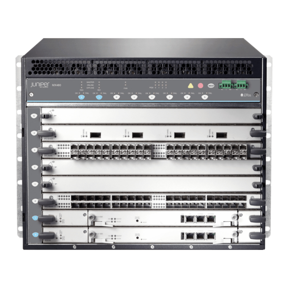
Page 33: Figure 2: Rear View Of A Fully Configured Ac-Powered Router Chassis
Chapter 1: Overview Figure 2: Rear View of a Fully Configured AC-Powered Router Chassis Figure 3: Rear View of a Fully Configured DC-Powered Router Chassis See Also MX480 Router Physical Specifications on page 140 Copyright © 2019, Juniper Networks, Inc. -
Page 34: Mx480 Component Redundancy
MX480 Universal Routing Platform Hardware Guide MX480 Component Redundancy A fully configured router is designed so that no single point of failure can cause the entire system to fail. Only a fully configured router provides complete redundancy. All other configurations provide partial redundancy. The following major hardware components are redundant: Host subsystem—The host subsystem consists of a Routing Engine functioning together... -
Page 35: Mx480 Router Hardware And Cli Terminology Mapping
Chapter 1: Overview MX480 Router Hardware and CLI Terminology Mapping The MX480 router supports the components in Table 5 on page Table 5: MX480 Router Hardware Components and CLI Terminology Component Hardware Model Number CLI Name Description Chassis CHAS-BP-MX480 “MX480 Router Physical Specifications” on... - Page 36 MX480 Universal Routing Platform Hardware Guide Table 5: MX480 Router Hardware Components and CLI Terminology (continued) Component Hardware Model Number CLI Name Description “MICs Supported by MX Series Routers” on “MX480 Modular Interface Card (MIC) MX Series Interface Module Description” on page 112...
-
Page 37: Mx480 Craft Interface Description
The alarm relay contacts are located on the upper right of the craft interface. Figure 5: Alarm Relay Contacts Alarm LEDs and Alarm Cutoff/Lamp Test Button on the MX480 Craft Interface Two large alarm LEDs are located at the upper right of the craft interface. The circular red LED lights to indicate a critical condition that can result in a system shutdown. -
Page 38: Mx480 Component Leds On The Craft Interface
Host Subsystem LEDs on the MX480 Craft Interface on page 38 Power Supply LEDs on the MX480 Craft Interface on page 39 DPC and MPC LEDs on the MX480 Craft Interface on page 39 FPC LEDs on the MX480 Craft Interface on page 39... -
Page 39: Power Supply Leds On The Mx480 Craft Interface
Power supply is functioning normally. On steadily Power supply has failed or power input has failed. DPC and MPC LEDs on the MX480 Craft Interface Each DPC or MPC has LEDs on the craft interface that indicate its status. The LEDs, labeled through , are located along the bottom of the craft interface. -
Page 40: Scb Leds On The Mx480 Craft Interface
On steadily FPC has failed. FAIL SCB LEDs on the MX480 Craft Interface Each SCB has two LEDs on the craft interface that indicates its status. The SCB LEDs, labeled , are located along the bottom of the craft interface. -
Page 41: Mx480 Cooling System
Figure 6: Cable Management Brackets Figure 7: Cable Management Brackets Installed on the Router See Also Maintaining Cables That Connect to MX480 DPCs, MPCs, MICs, or PICs on page 316 Replacing the MX480 Cable Management Brackets on page 231 MX480 Cooling System... -
Page 42: Figure 8: Airflow Through The Chassis
MX480 Universal Routing Platform Hardware Guide The cooling system components work together to keep all router components within the acceptable temperature range (see Figure 8 on page Figure 9 on page 43, and Figure 10 on page 43). The router has one fan tray and one air filter that install vertically in the rear of the router. -
Page 43: Mx480 Fan Led
For more information, see “Fan LED on the MX480 Craft Interface” on page See Also Maintaining the MX480 Fan Tray on page 236 Troubleshooting the MX480 Cooling System on page 355 Copyright © 2019, Juniper Networks, Inc. -
Page 44: Mx480 Power System Description
MX480 Universal Routing Platform Hardware Guide MX480 Power System Description The MX480 router uses either AC or DC power supplies. The MX480 router is configurable with two, three, or four AC power supplies or two or four DC power supplies. The power supplies connect to the midplane, which distributes the different output voltages produced by the power supplies to the router components, depending on their voltage requirements. -
Page 45: Mx480 Ac Power System
MX480 AC Power Supply LEDs on page 47 AC Electrical Specifications for the MX480 Router on page 47 AC Power Circuit Breaker Requirements for the MX480 Router on page 48 AC Power Cord Specifications for the MX480 Router on page 49... -
Page 46: Ac Power Supply Configurations
AC Power Supply Configurations The MX480 high-capacity and normal-capacity power supplies each support either of the following AC power configurations: In the low-line (110 V) AC power configuration, the MX480 router contains three or four AC power supplies (see Figure 11 on page... -
Page 47: Mx480 Ac Power Supply Leds
Check LEDs for more information. AC OK DC OK AC Electrical Specifications for the MX480 Router Table 14 on page 47 lists the AC power supply electrical specifications; Table 15 on page 48 lists the AC power system specifications. -
Page 48: Ac Power Circuit Breaker Requirements For The Mx480 Router
4100 W per system See Also Calculating Power Requirements for MX480 Routers on page 158 AC Power Circuit Breaker Requirements for the MX480 Router Each AC power supply has a single AC appliance inlet located on the power supply that requires a dedicated AC power feed. -
Page 49: Ac Power Cord Specifications For The Mx480 Router
Chapter 1: Overview AC Power Cord Specifications for the MX480 Router Each AC power supply has a single AC appliance inlet located on the power supply that requires a dedicated AC power feed. Most sites distribute power through a main conduit that leads to frame-mounted power distribution panels, one of which can be located at the top of the rack that houses the router. -
Page 50: Figure 13: Ac Plug Types
MX480 Universal Routing Platform Hardware Guide Figure 13: AC Plug Types WARNING: The AC power cord for the router is intended for use with the router only and not for any other use. WARNING: Translation from Japanese: The attached power cable is only for this product. -
Page 51: Outstanding Issues With The Mx480 Router
(60-61V instead of 57V) under some conditions, such as when the load is nearly 100% and the operating temperature exceeds 40C. There is an input mode switch on each MX480 DC high capacity power supply, covered by a small plate. The input mode switch tells the system what capacity feed is... -
Page 52: Errata With The Mx480 Router Documentation
You need to insert the optics and fiber firmly until the latch is securely in place. [PR/98055] Do not mix AC and DC power supplies on an MX480 router. Mixing of AC supplies and DC supplies may damage your chassis. [PR/233340]... -
Page 53: Mx480 Dc Power System
MX480 DC Power Supply Description on page 53 MX480 DC Power Supply LEDs on page 54 DC Power Supply Electrical Specifications for the MX480 Router on page 55 DC Power Circuit Breaker Requirements for the MX480 Router on page 56... -
Page 54: Dc Power Supply Configurations
MX480 Universal Routing Platform Hardware Guide Figure 15: High-Capacity DC Power Supply DC Power Supply Configurations In the DC power configuration, the MX480 router contains either two or four DC power supplies (see Figure 14 on page 53) located at the rear of the chassis in slots... -
Page 55: Dc Power Supply Electrical Specifications For The Mx480 Router
DC input is present and is connected in correct polarity. Yellow DC input is present, but not in valid operating range or connected in reverse polarity. DC Power Supply Electrical Specifications for the MX480 Router Table 20 on page 55 lists the DC power supply electrical specifications. -
Page 56: Dc Power Circuit Breaker Requirements For The Mx480 Router
(maximum) per system See Also Calculating Power Requirements for MX480 Routers on page 158 DC Power Circuit Breaker Requirements for the MX480 Router Each DC power supply has a single DC input (–48 VDC and return) that requires a dedicated circuit breaker. If you plan to operate a maximally configured DC-powered router with normal-capacity power supplies, we recommend that you use a dedicated customer site circuit breaker rated for 40 A (–48 VDC) minimum, or as required by local... -
Page 57: Dc Power Source Cabling For The Mx480 Router
See Also In Case of an Electrical Accident Connecting Power to a DC-Powered MX480 Router with Normal Capacity Power Supplies on page 207 Replacing an MX480 DC Power Supply Cable on page 327... -
Page 58: Dc Power Cable Specifications For The Mx480 Router
MX480 Universal Routing Platform Hardware Guide DC Power Cable Specifications for the MX480 Router DC Power Cable Lug Specifications—The accessory box shipped with the router includes the cable lugs that attach to the terminal studs of each power supply (see Figure 17 on page 58). -
Page 59: Mx480 Host Subsystem Description
For more information, see “Host Subsystem LEDs on the MX480 Craft Interface” on page MX480 Midplane Description The midplane is located toward the rear of the chassis and forms the rear of the card... -
Page 60: Mx480 Routing Engine Description
See Also MX480 Router Description on page 29 MX480 Chassis Description on page 32 MX480 Dense Port Concentrator (DPC) Description on page 90 MX480 Modular Port Concentrator (MPC) Description on page 124 MX-Series Switch Control Board (SCB) Overview on page 135... -
Page 61: Routing Engine Components
Button 5— LEDs— ONLINE, OK/FAIL, MASTER 10— SSD card slot cover Routing Engine Components NOTE: For specific information about Routing Engine components (for example, the amount of DRAM), issue the show vmhost hardware command. Copyright © 2019, Juniper Networks, Inc. -
Page 62: Routing Engine Interface Ports
MX480 Universal Routing Platform Hardware Guide Routing Engine Interface Ports Three ports, located on the right side of the Routing Engine, connect the Routing Engine to one or more external devices on which system administrators can issue Junos OS command-line interface (CLI) commands to manage the router. -
Page 63: Mx480 Routing Engine Leds
Chapter 1: Overview See Also MX480 Router Description on page 29 MX480 Routing Engine LEDs on page 63 MX480 Host Subsystem Description on page 59 MX-Series Switch Control Board (SCB) Overview on page 135 MX480 Routing Engine LEDs Each Routing Engine has four LEDs that indicate its status. The LEDs, labeled... -
Page 64: Routing Engine Leds (Re-S-X6-64G)
On steadily This Routing Engine is the Master Routing Engine. MASTER See Also Replacing an MX480 Routing Engine on page 243 RE-S-1800 Routing Engine Description Figure 24 on page 65 shows RE-S-1800 routing engine. Copyright © 2019, Juniper Networks, Inc. -
Page 65: Re-S-1800 Routing Engine Components
Extractor clips—Used for inserting and extracting the Routing Engine. Captive screws—Secure the Routing Engine in place. NOTE: For specific information about Routing Engine components (for example, the amount of DRAM), issue the show chassis routing-engine command. Copyright © 2019, Juniper Networks, Inc. -
Page 66: Re-S-1800 Routing Engine Leds
MX480 Universal Routing Platform Hardware Guide RE-S-1800 Routing Engine LEDs Each Routing Engine has four LEDs that indicate its status. The LEDs, labeled MASTER , and , are located directly on the faceplate of the Routing STORAGE ONLINE OK/FAIL Engine. -
Page 67: Re-S-X6-64G Routing Engine Description
On steadily Routing Engine has failed. OK/FAIL See Also MX240 Routing Engine Description MX480 Routing Engine Description on page 60 MX960 Routing Engine Description RE-S-X6-64G Routing Engine Description Figure 25 on page 67 shows the Routing Engine. Figure 25: RE-S-X6-64G Routing Engine Front View 1—... -
Page 68: Re-S-X6-64G Routing Engine Boot Sequence
MX480 Universal Routing Platform Hardware Guide Each RE-S-X6-64G Routing Engine (shown in Figure 25 on page 67) consists of the following components: CPU—Runs Junos OS to maintain the routing tables and routing protocols. EEPROM—Stores the serial number of the Routing Engine. -
Page 69: Re-S-X6-64G Routing Engine Leds
Routing Engine is powering up. OK/FAIL Yellow On steadily Routing Engine is not powering up, which indicates failure. MASTER Blue On steadily This Routing Engine is the Master Routing Engine. See Also MX240 Routing Engine Description Copyright © 2019, Juniper Networks, Inc. -
Page 70: Routing Engine Specifications
MX480 Universal Routing Platform Hardware Guide MX960 Routing Engine Description Routing Engine Specifications Table 28 on page 70 lists the current specifications for Routing Engines supported on M Series, MX Series, and T Series routers. Table 29 on page 73 lists the specifications for end-of-life Routing Engines. - Page 71 SCBE2, SCBE3 card RE-S-MX104 1.8-GHz 4 GB Gigabit – 8 GB NAND 13.2 – Ethernet Flash RE-B-1800x1-4G 1.73-GHz 4 GB Gigabit 64 GB SSD 4 GB 12.1R2, 11.4R4, – Ethernet CompactFlash and 12.2R1 card Copyright © 2019, Juniper Networks, Inc.
- Page 72 MX480 Universal Routing Platform Hardware Guide Table 28: Routing Engine Specifications (continued) Routing Connection First Junos OS Switch Control Engine Processor Memory to PFEs Disk Media Support Board R E - M X 2 0 0 0 - 1 8 0 0 x 4 1.8- GHz...
-
Page 73: Table 29: End-Of-Life Routing Engine Specifications
RE-850-1536 850-MHz 1536 MB Fast 40 GB hard 1 GB PSN-2011-04-226 Pentium III Ethernet disk CompactFlash card RE-M40 200-MHz 256 MB Fast 6.4 GB hard 80 MB FA-HW-0101-001 Pentium Ethernet disk CompactFlash card Copyright © 2019, Juniper Networks, Inc. -
Page 74: Supported Routing Engines By Router
MX480 Universal Routing Platform Hardware Guide Table 29: End-of-Life Routing Engine Specifications (continued) Routing Connection First Junos OS Engine Processor Memory to PFEs Disk Media Support EOL Details RE-M40-333-7 68 333-MHz 768 MB Fast 10 GB hard 80 MB PSN-2003-01-063... -
Page 75: M7I Routing Engines
32-bit Junos OS only. Table 31: M10i Routing Engines First Supported Name in CLI 32-bit Junos OS Management Internal Ethernet Model Number Output Release Ethernet Interface Interface RE-400-768 (EOL details: fxp0 fxp1 RE-5.0 TSB16445 fxp2 Copyright © 2019, Juniper Networks, Inc. -
Page 76: M40E Routing Engines
MX480 Universal Routing Platform Hardware Guide Table 31: M10i Routing Engines (continued) First Supported Name in CLI 32-bit Junos OS Management Internal Ethernet Model Number Output Release Ethernet Interface Interface RE-850-1536 (EOL details: RE-850 fxp0 fxp1 TSB15553 fxp2 RE-B-1800X1-4G 11.4R4... -
Page 77: M320 Routing Engines
12.1R3 bcm0 RE-A-1800X4-8G RE-A-1800X4 11.4R5 10.4 fxp0 12.1R3 12.2 MX5, MX10, MX40, and MX80 Routing Engine Table 35 on page 78 lists the Routing Engines supported by the MX5, MX10, MX40, and MX80 routers. Copyright © 2019, Juniper Networks, Inc. -
Page 78: Mx104 Routing Engines
MX480 Universal Routing Platform Hardware Guide Table 35: MX5, MX10, MX40, and MX80 Routing Engine First Supported First Supported Management Model Name in CLI 32-bit Junos OS 64-bit Junos OS Ethernet Number Output Release Release Interface Internal Ethernet Interface Built-in Routing Routing Engine 12.3... -
Page 79: Mx480 Routing Engines
– 18.1R1 fxp0 ixlv0, igb0 RE-S-2X00x6-128 MX480 Routing Engines Table 38 on page 79 lists the Routing Engines supported by MX480 routers. Table 38: MX480 Supported Routing Engines First Supported First Supported Management Name in CLI 32-bit Junos OS 64-bit Junos OS... -
Page 80: Mx960 Routing Engines
MX480 Universal Routing Platform Hardware Guide Table 38: MX480 Supported Routing Engines (continued) First Supported First Supported Management Name in CLI 32-bit Junos OS 64-bit Junos OS Ethernet Internal Ethernet Model Number Output Release Release Interface Interface RE-S-1800X4-8G RE-S-1800X4 11.4R5 10.4... -
Page 81: Mx2008 Routing Engines
Name in CLI First Supported 64-bit Junos Ethernet Ethernet Model Number Output OS Release Interface Interface REMX2008-X8-64G 15.1F7 fxp0 ixlv0 RE-MX2008-X8-64G ixlv1 REMX2008-X8-64G-LT 17.2R1 fxp0 ixlv0 REMX2008-X8-64G-L T ixlv1 REMX2008-X8-128G RE-MX2008-X8-128G 18.2R1 fxp0 ixlv0 ixlv1 Copyright © 2019, Juniper Networks, Inc. -
Page 82: Mx2010 Routing Engines
MX480 Universal Routing Platform Hardware Guide MX2010 Routing Engines Table 41 on page 82 lists the Routing Engines supported by MX2010 routers. Table 41: MX2010 Supported Routing Engines Management Name in CLI First Supported 64-bit Junos Ethernet Internal Ethernet Model Number... -
Page 83: Mx10003 Routing Engines
Routing Engines supported on the MX10008 router. Table 44: MX10008 Routing Engines Name in CLI First Supported Management Ethernet Internal Ethernet Model Number Output Junos OS Release Interface Interface JNP10K-RE1 RE X10 18.2R1 bme0 bme1 Copyright © 2019, Juniper Networks, Inc. -
Page 84: Ptx1000 Routing Engines
MX480 Universal Routing Platform Hardware Guide PTX1000 Routing Engines Table 45 on page 84 lists the Routing Engine supported on the PTX1000. NOTE: The PTX1000 supports 64-bit Junos OS only. Table 45: PTX1000 Routing Engines Name in CLI First Supported Junos OS... -
Page 85: Ptx10008 And Ptx10016 Routing Engines
Routing Engines supported on the PTX10008 and PTX10016 routers. Table 48: PTX10008 and PTX10016 Routing Engines First Supported Management Internal Ethernet Model Number Name in CLI Output Junos OS Release Ethernet Interface Interface JNP10K-RE0 17.2R1 em0, em1 bme0 RE-PTX-2X00x4 bme1 Copyright © 2019, Juniper Networks, Inc. -
Page 86: T320 Routing Engines
MX480 Universal Routing Platform Hardware Guide Table 48: PTX10008 and PTX10016 Routing Engines (continued) First Supported Management Internal Ethernet Model Number Name in CLI Output Junos OS Release Ethernet Interface Interface JNP10K-RE1 (on RE X10 18.2R1 bme0 PTX10008) bme1 T320 Routing Engines Table 49 on page 86 lists the Routing Engines supported by the T320 router. -
Page 87: T1600 Routing Engines
Model Number Output Junos OS Release Release Interface Interface RE-600-2048 (EOL RE-3.0 – fxp0 fxp1 details: TSB14373 RE-3.0 fxp2 (RE-600) RE-1600-2048 (EOL – fxp0 fxp1 RE-4.0 details: TSB14374 (RE-1600) fxp2 RE-A-2000-4096 RE-A-2000 – fxp0 bcm0 Copyright © 2019, Juniper Networks, Inc. -
Page 88: T4000 Routing Engines
MX480 Universal Routing Platform Hardware Guide Table 51: T1600 Routing Engines (continued) First Supported Management Internal Name in CLI First Supported 32-bit 64-bit Junos OS Ethernet Ethernet Model Number Output Junos OS Release Release Interface Interface RE-DUO-C1800-8G RE-TXP-LCC 32-bit Junos OS on a T1600... -
Page 89: Tx Matrix Plus Routing Engines
The TX Matrix Plus router supports the CB-TXP control board. TX Matrix Plus (with 3D SIBs) Routing Engines Table 55 on page 90 lists the Routing Engines supported by the TX Matrix Plus router with 3D SIBs. Copyright © 2019, Juniper Networks, Inc. -
Page 90: Mx480 Interface Modules-Dpcs
MX480 DPC Port and Interface Numbering on page 92 MX480 Dense Port Concentrator (DPC) LEDs on page 95 DPCs Supported on MX240, MX480, and MX960 Routers on page 95 MX480 Dense Port Concentrator (DPC) Description A Dense Port Concentrator (DPC) is optimized for Ethernet density (see Figure 27 on page 91). -
Page 91: Dpc Components
Two Gigabit Ethernet interfaces that allow control information, route information, and statistics to be sent between the Routing Engine and the CPU on the DPCs. Two interfaces from the SCBs that enable the DPCs to be powered on and controlled. Copyright © 2019, Juniper Networks, Inc. -
Page 92: Mx480 Dpc Port And Interface Numbering
Ethernet interface so—SONET/SDH interface xe—10-Gigabit Ethernet interface For a complete list of media types, see Interface Naming Overview. fpc—Slot in which the DPC is installed. On the MX480 router, the DPCs are represented in the CLI as FPC 0 through FPC 5 pic—Logical PIC on the DPC. -
Page 93: Figure 29: Mx480 Dpc Interface Port Mapping
MX Series Interface Module Reference port—Port number. The MX480 router supports up to six DPCs that install horizontally and are numbered 0 through 5 from bottom to top. Figure 29 on page 93 shows a 40-port Gigabit Ethernet DPC with SFP installed in slot on the MX480 router. - Page 94 MX480 Universal Routing Platform Hardware Guide Xcvr 6 REV 01 740-011613 PCE1H5P SFP-SX Xcvr 7 REV 01 740-011782 PCH2UFG SFP-SX Xcvr 8 REV 02 740-011613 AM0947SEYU2 SFP-SX Xcvr 9 REV 02 740-011613 AM0947SEYTQ SFP-SX PIC 1 BUILTIN BUILTIN 10x 1GE(LAN)
-
Page 95: Mx480 Dense Port Concentrator (Dpc) Leds
. For more information about the DPC LEDs on the craft interface, see “DPC and MPC LEDs on the MX480 Craft Interface” on page Each DPC also has LEDs located on the faceplate. For more information about LEDs on the DPC faceplate, see the “LEDs” section for each DPC in the... - Page 96 MX480 Universal Routing Platform Hardware Guide Table 56: DPCs Supported in MX240, MX480, and MX960 Routers (continued) Maximum DPC Model Throughput First Junos DPC Name Number Ports per DPC OS Release Gigabit Ethernet DPC with SFP DPC-R-40GE-SFP 40 Gbps EOL (see...
- Page 97 Chapter 1: Overview Table 56: DPCs Supported in MX240, MX480, and MX960 Routers (continued) Maximum DPC Model Throughput First Junos DPC Name Number Ports per DPC OS Release 10-Gigabit Ethernet Enhanced Queuing Ethernet Services DPCE-X-Q-4XGE-XFP 40 Gbps DPC with XFP...
-
Page 98: Mx480 Interface Modules-Fpcs And Pics
MX480 Flexible PIC Concentrator (FPC) Description on page 98 MX480 Flexible PIC Concentrator (FPC) LEDs on page 100 FPCs Supported by MX240, MX480, and MX960 Routers on page 100 MX480 PIC Description on page 100 MX480 PIC Port and Interface Numbering on page 101... -
Page 99: Fpc Components
Chapter 1: Overview Figure 31: Typical FPCs Supported on the MX480 Router MX-FPC2 FPC3 If a slot is not occupied by a DPC, an FPC, or an SCB, a blank panel must be installed to shield the empty slot and to allow cooling air to circulate properly through the router. -
Page 100: Mx480 Flexible Pic Concentrator (Fpc) Leds
“FPC LEDs on the MX480 Craft Interface” on page FPCs Supported by MX240, MX480, and MX960 Routers An FPC occupies two slots when installed in an MX240, MX480, or MX960 router. The maximum number of supported FPCs varies per router: MX960 router—6 FPCs... -
Page 101: Mx480 Pic Port And Interface Numbering
PICs are hot-removable and hot-insertable. Up to two PICs can be installed in the slots in each FPC. Up to three FPCs can be installed in an MX480 router. PICs used in a Type 2 FPC have captive screws at their upper and lower corners. PICs used in a Type 3 FPC have an upper ejector handle and a lower captive screw. -
Page 102: Figure 32: Mx480 Pic Interface Port Mapping
MX480 Universal Routing Platform Hardware Guide Figure 32: MX480 PIC Interface Port Mapping show chassis hardware command output displays a Channelized OC12/STM4 Enhanced IQ (IQE) PIC ( ) installed in 4x CHOC12 IQE SONET MX FPC Type 2 user@host> show chassis hardware... -
Page 103: Mx480 Pic Leds
Chapter 1: Overview coc12-3/0/3 See Also MX480 Router Hardware and CLI Terminology Mapping on page 35 MX480 PIC LEDs Each PIC has LEDs located on the faceplate. For more information about LEDs on the PIC faceplate, see the “LEDs” section for each PIC in the... -
Page 104: Mx480 Interface Modules-Mpcs And Mics
MIC/MPC Compatibility The following tables provide a compatibility matrix for the MICs currently supported by MPC1, MPC2, MPC3, MPC6, MPC8, and MPC9 on MX240, MX480, MX960, MX2008, MX2010, MX2020, and MX10003 routers. Each table lists the first Junos OS release in which the MPC supports the MIC. - Page 105 11.4 11.4 MIC-3D-8CHOC3-4CHOC12 MIC-4COC3-2COC12-G, MIC-8COC3-4COC12-G (Channelized SONET/SDH OC3/STM1 (Multi-Rate) MICs with SFP) MIC-3D-16CHE1-T1-CE 13.2 13.2 12.3 12.3 (Channelized E1/T1 NOTE: Support for NOTE: Support for Circuit Emulation MIC) Non-Channelized MIC Non-Channelized MIC only. only. Copyright © 2019, Juniper Networks, Inc.
-
Page 106: Table 60: Mic/Mpc2 Compatibility
MX480 Universal Routing Platform Hardware Guide Table 59: MIC/MPC1 Compatibility (continued) MIC Name MPC1 MPC1E MPC1 Q MPC1E Q MIC-3D-8DS3-E3, 11.4 11.4 11.4 11.4 MIC-3D-8CHDS3-E3-B (DS3/E3 MIC) NOTE: You cannot run Channelized DS3 (MIC-3D-8CHDS3-E3) on non-Q MPCs. Channelized DS3 is supported only on Q and EQ-based MPCs. - Page 107 M I C - 4 C O C 3 - 2 C O C 1 2 - G , 14.2R3 with option M I C - 8 C O C 3 - 4 C O C 1 2 - G Junos Continuity (Channelized SONET /SDH OC3/STM1 (Multi-Rate) MICs with SFP) Copyright © 2019, Juniper Networks, Inc.
- Page 108 MX480 Universal Routing Platform Hardware Guide Table 60: MIC/MPC2 Compatibility (continued) MPC2E MPC2E MPC2E Name MPC2 M P C 2 E MPC2 Q MPC2E Q MPC2 EQ MPC2E P NG Q M I C - 3 D - 1 6 C H E 1 - T 1 - C E 13.2...
-
Page 109: Table 61: Mic/Mpc3 Compatibility
12.2 14.1R4, 14.2R3 with Junos 14.1R4, 14.2R3 with Junos Continuity Continuity (100-Gigabit Ethernet MIC with CXP) 15.1 15.1 MIC3-100G-DWDM 15.1F5 15.1F5 15.1F5 15.1F6 15.1F6 15.1F6 (100-Gigabit DWDM OTN MIC with CFP2-ACO) 17.1R1 17.1R1 17.1R1 Copyright © 2019, Juniper Networks, Inc. - Page 110 MX480 Universal Routing Platform Hardware Guide Table 61: MIC/MPC3 Compatibility (continued) MIC Name MPC3E MPC3E NG MPC3E NG Q MIC-3D-4OC3OC12-1OC48 13.3 14.1R4, 14.2R3 with Junos 14.1R4, 14.2R3 with Junos Continuity Continuity MIC-3D-8OC3OC12-4OC48 15.1 15.1 (SONET/SDH OC3/STM1 (Multi-Rate) MICs with SFP) MIC-3D-1OC192-XFP 13.3...
-
Page 111: Table 62: Mic/Mpc6 Compatibility
Table 63: MIC/MPC8 Compatibility MIC Name MPC8E MIC-MRATE 15.1F5 with Junos Continuity 16.1R1 MIC MRATE MIC-MACSEC-MRATE 17.4 Multi-Rate Ethernet MIC Table 64: MIC/MPC9 Compatibility MIC Name MPC9E MIC-MRATE 15.1F5 with Junos Continuity 16.1R1 MIC MRATE Copyright © 2019, Juniper Networks, Inc. -
Page 112: Mx480 Modular Interface Card (Mic) Description
MPC. See Also Maintaining MX480 MICs on page 288 Troubleshooting the MX480 MICs on page 360 Replacing an MX480 MIC on page 289 MX480 MIC Port and Interface Numbering Each port on a MIC corresponds to a unique interface name in the CLI. - Page 113 Ethernet interface so—SONET/SDH interface xe—10-Gigabit Ethernet interface For a complete list of media types, see Interface Naming Overview. fpc—Slot in which the MPC is installed. On the MX480 router, the MPCs are represented in the CLI as through FPC 0 FPC 5 pic—Logical PIC on the MIC, numbered 0 or 1 when installed in slot 0, and 2 or 3 when...
-
Page 114: Figure 33: Mx480 Mic Interface Port Mapping
NOTE: The 20-port Gigabit Ethernet MIC with SFP-E has a different port numbering. See Gigabit Ethernet MIC with SFP (E) Figure 33: MX480 MIC Interface Port Mapping The MIC contains two logical PICs, numbered through in the CLI. Each logical... -
Page 115: Mx480 Modular Interface Card (Mic) Leds
See Also MX480 Router Hardware and CLI Terminology Mapping on page 35 MX480 Modular Interface Card (MIC) LEDs Each MIC has LEDs located on the faceplate. For more information about LEDs on the MIC faceplate, see the “LEDs” section for each MIC in the... -
Page 116: Mics Supported By Mx Series Routers
Junos OS release for MICs on MX80 and MX104 routers. Table 70 on page 123 lists the first supported Junos OS release for MICs on MX10003 router. Table 66: MICs Supported by MX240, MX480, MX960 and MX2008 Routers MX240, MX480, and MX960 MIC Name MIC Model Number... - Page 117 Chapter 1: Overview Table 66: MICs Supported by MX240, MX480, MX960 and MX2008 Routers (continued) MX240, MX480, and MX960 MIC Name MIC Model Number Ports Routers MX2008 Routers 10-Gigabit Ethernet MIC with MIC3-3D-10XGE-SFPP 12.3 15.1F7 SFP+ (10 Ports) 10-Gigabit Ethernet MIC with MIC6-10G 15.1F7...
-
Page 118: Table 67: Mics Supported By Mx2010 And Mx2020 Routers
MX480 Universal Routing Platform Hardware Guide Table 66: MICs Supported by MX240, MX480, MX960 and MX2008 Routers (continued) MX240, MX480, and MX960 MIC Name MIC Model Number Ports Routers MX2008 Routers Channelized OC3/STM1 MIC-3D-4COC3-1COC12-CE 12.2 15.1F7 (Multi-Rate) Circuit Emulation MIC with SFP... - Page 119 CFP2-ACO 15.1F6 15.1F6 17.1R1 17.1R1 Multi-Rate SONET/SDH OC3/STM1 MIC-3D-4OC3OC12-1OC48 12.3 12.3 (Multi-Rate) MICs with SFP SONET/SDH OC3/STM1 MIC-3D-8OC3OC12-4OC48 12.3 12.3 (Multi-Rate) MICs with SFP Channelized SONET/SDH MIC-3D-4CHOC3-2CHOC12 12.3 12.3 OC3/STM1 (Multi-Rate) MICs with SFP Copyright © 2019, Juniper Networks, Inc.
-
Page 120: Table 68: Mics Supported By Mx5, Mx10, And Mx40 Routers
MX480 Universal Routing Platform Hardware Guide Table 67: MICs Supported by MX2010 and MX2020 Routers (continued) MIC Name MIC Model Number Ports MX2010 Routers MX2020 Routers Channelized SONET/SDH MIC-3D-8CHOC3-4CHOC12 12.3 12.3 OC3/STM1 (Multi-Rate) MICs with SFP Channelized OC3/STM1 MIC-3D-4COC3-1COC12-CE 12.3 12.3... - Page 121 MIC with SFP (H) Tri-Rate Tri-Rate MIC MIC-3D-40GE-TX – 11.2R4 11.2R4 Services Multiservices MIC MS-MIC-16G 13.2 13.2 13.2 Rear slot only. Rear slot Rear slot only. only. SONET/SDH OC192/STM64 MIC MIC-3D-1OC192-XFP 12.2 12.2 12.2 with XFP Copyright © 2019, Juniper Networks, Inc.
-
Page 122: Table 69: Mics Supported By Mx80 And Mx104 Routers
MX480 Universal Routing Platform Hardware Guide Table 69: MICs Supported by MX80 and MX104 Routers MIC Name MIC Model Number Ports MX80 MX104 ATM MIC with SFP MIC-3D-8OC3-2OC12-ATM 12.1 13.3 DS3/E3 DS3/E3 MIC MIC-3D-8DS3-E3, 11.4 13.3 MIC-3D-8CHDS3-E3-B Circuit Emulation Channelized E1/T1 Circuit MIC-3D-16CHE1-T1-CE 13.2R2... -
Page 123: Table 70: Mics Supported By Mx10003 Router
MX10003 Multi-Rate Multi-Rate Ethernet MIC (12-Port JNP-MIC1 17.3 Multi-Rate MIC with QSFP+) Multi-Rate Ethernet MIC (12-Port JNP-MIC1-MACSEC 17.3R2 Multi-Rate MACsec MIC with QSFP+) See Also MX Series MIC Overview MIC/MPC Compatibility on page 104 Copyright © 2019, Juniper Networks, Inc. -
Page 124: Mx480 Modular Port Concentrator (Mpc) Description
MPCs interface with the power supplies and Switch Control Boards (SCBs). You must install redundant SCBs to support full line-rate. The MX480 router supports up to six MPCs. You must install a high-capacity fan tray to use an MPC. For power requirements, see “Calculating Power Requirements for MX480... -
Page 125: Mpc Components
Chapter 1: Overview Figure 34: Typical MPC Supported on the MX Series Router MPC (empty) Figure 35: MPC Installed Horizontally in the MX480 Router MX 48 0 SC B SC B MPC Components Each MPC consists of the following components: MPC card carrier, which includes two MIC slots (excludes the fixed configuration MPC). -
Page 126: Mx480 Modular Port Concentrator (Mpc) Leds
FAIL craft interface, see “DPC and MPC LEDs on the MX480 Craft Interface” on page Each MPC also has LEDs located on the faceplate. For more information about LEDs on the MPC faceplate, see the “LEDs” section for each MPC in the... -
Page 127: Table 71: Mpcs Supported By Mx240, Mx480, Mx960, Mx2008, Mx2010
Chapter 1: Overview Table 71: MPCs Supported by MX240, MX480, MX960, MX2008, MX2010, MX2020, and MX10003 Routers First Junos OS Release First First First MX240, Junos OS First Junos First Junos Junos OS Junos OS MX480, Release Release Release Release on... - Page 128 MX480 Universal Routing Platform Hardware Guide Table 71: MPCs Supported by MX240, MX480, MX960, MX2008, MX2010, MX2020, and MX10003 Routers (continued) First Junos OS Release First First First MX240, Junos OS First Junos First Junos Junos OS Junos OS MX480,...
- Page 129 Chapter 1: Overview Table 71: MPCs Supported by MX240, MX480, MX960, MX2008, MX2010, MX2020, and MX10003 Routers (continued) First Junos OS Release First First First MX240, Junos OS First Junos First Junos Junos OS Junos OS MX480, Release Release Release...
-
Page 130: Mx480 Application Services Modular Line Card Description
Junos Content Encore system, a high-throughput, solid state storage platform for media rich content delivery. Additionally, the AS MLC can serve as the platform for Juniper Networks JunosV App Engine, powering a host of network applications directly embedded into your MX Series 5G Universal Routing Platforms. -
Page 131: As Mlc Components
AS MLC Components Each AS MLC consists of the following components: AS MLC Modular Carrier Card (AS MCC), which fits horizontally in front of the MX480 router, includes two slots for the Application Services Modular Storage Card (AS MSC) and Application Services Modular Processing Card (AS MXC) -
Page 132: Mx480 Application Services Modular Storage Card Description
For DC power supply: PWR-FAN-MX480-DC-HC-U and PWR-MX480-2520-DC-S Fan tray—FFANTRAY-MX480-HC See Also Replacing an MX480 AS MLC on page 307 Replacing an MX480 AS MSC on page 311 Replacing an MX480 AS MXC on page 314 MX480 Application Services Modular Storage Card Description Application Services Modular Storage Card (AS MSC) is a NAND Flash––based card that... -
Page 133: Mx480 Application Services Modular Processing Card Description
Chapter 1: Overview Figure 37: Application Services Modular Storage Card See Also Replacing an MX480 AS MSC on page 311 MX480 Application Services Modular Processing Card Description The Application Services Modular Processing Card (AS MXC) is a pluggable X86-based card that can be inserted into the lower slot of the Application Services Modular Line Card (AS MLC). -
Page 134: Mx480 As Msc Leds
AS MSC storage operation has an error. – AS MSC storage operation is not activated. See Also Replacing an MX480 AS MSC on page 311 MX480 AS MXC LEDs Two LEDs ( ) indicate the status of the AS MXC and are located on the AS MXC. -
Page 135: Mx-Series Switch Control Board (Scb) Overview
Depending on the MX chassis and the level of redundancy, the number of SCBs can vary. The MX240 and MX480 require two SCBs for 1+1 redundancy, whereas the MX960 requires three SCBs for 2+1 redundancy. -
Page 136: Cli Identification
MX480 Universal Routing Platform Hardware Guide Table 74: Switch Control Board Capacities for MX Series Universal Routers (Full-Duplex) (continued) MX240 Fabric MX480 Fabric MX960 Fabric Description Fabric Bandwidth Per Slot Bandwidth Bandwidth Bandwidth Switch Control Board Up to 240 Gbps (non-redundant Up to 465 Gbps Up to 1.39 Tbps... - Page 137 | match SCBE3 Item Version Part number Serial number FRU model number CB 0 REV 23 750-070866 CALH6007 SCBE3-MX-S CB 1 REV 23 750-070866 CALH6017 SCBE3-MX-S CB 2 REV 23 750-070866 CALH6015 SCBE3-MX-S Copyright © 2019, Juniper Networks, Inc.
- Page 138 MX480 Universal Routing Platform Hardware Guide Copyright © 2019, Juniper Networks, Inc.
-
Page 139: Site Planning, Preparation, And Specifications
MX480 Site Guidelines and Requirements on page 140 MX480 Power Planning on page 149 MX480 Network Cable and Transceiver Planning on page 162 MX480 Management, and Console Port Specifications and Pinouts on page 166 MX480 Site Preparation Checklist The checklist in... -
Page 140: Mx480 Site Guidelines And Requirements
162 Related MX480 Router Rack Requirements on page 146 Documentation MX480 Router Clearance Requirements for Airflow and Hardware Maintenance on page 147 MX480 Router Cabinet Size and Clearance Requirements on page 148 MX480 Site Guidelines and Requirements MX480 Router Physical Specifications on page 140... -
Page 141: Chapter 2 Site Planning, Preparation, And Specifications
6.8 lb (3.08 kg) 17 in (43.2 cm) 22 in (55.9 cm) 1.5 in (3.8 cm) Air filter 1.0 lb (0.5 kg) 0.31 in (0.8 cm) 22.23 in (56.5 cm) 10.1 in (25.6 cm) Copyright © 2019, Juniper Networks, Inc. -
Page 142: Mx480 Router Environmental Specifications
14.5 in (36.8 cm) 4 in (10.2 cm) 1.75 in (4.4 cm) See Also MX480 Chassis Lifting Guidelines on page 390 MX480 Router Description on page 29 MX480 Chassis Description on page 32 MX480 Router Environmental Specifications Table 78 on page 142 specifies the environmental specifications required for normal router operation. -
Page 143: Mx480 Chassis Grounding Specifications
Articles 110-16, 110-17, and 110-18 of the National Electrical Code, ANSI/NFPA 70. See Also Tools and Parts Required to Maintain the MX480 Router In Case of an Electrical Accident MX480 Chassis Grounding Specifications... -
Page 144: Mx480 Router Grounding Cable Lug Specifications
MX480 Universal Routing Platform Hardware Guide Figure 39: Connecting AC Power to the Router Figure 40: Connecting DC Power to the Router MX480 Router Grounding Cable Lug Specifications The accessory box shipped with the router includes one cable lug that attaches to the... -
Page 145: Mx480 Router Grounding Cable Specifications
This separate protective earthing terminal must be permanently connected to earth. See Also Tools and Parts Required for MX480 Router Grounding and Power Connections on page 203 Grounding the MX480 Router on page 204 Preventing Electrostatic Discharge Damage to an MX480 Router on page 388 Copyright ©... -
Page 146: Mx480 Router Rack Requirements
Cabinets, Racks, Panels, and Associated Equipment (document number EIA-310-D) published by the Electronic Components Industry Association (ECIA) ). You can stack five MX480 routers in a rack that has at least http://www.ecianow.org 48 U (84 in. or 2.13 m) of usable vertical space. -
Page 147: Spacing Of Mounting Bracket Holes
For maximum stability, also secure the rack to ceiling brackets. See Also Installation Safety Warnings for Juniper Networks Devices MX480 Router Clearance Requirements for Airflow and Hardware Maintenance When planning the installation site, you need to allow sufficient clearance around the rack (see Figure 43 on page... -
Page 148: Mx480 Router Cabinet Size And Clearance Requirements
Care must also be taken around cables to ensure that no leakage of air in situations where recirculation may result. Figure 43: Clearance Requirements for Airflow and Hardware Maintenance for an MX480 Router Chassis... -
Page 149: Mx480 Router Cabinet Airflow Requirements
MX480 Site Preparation Checklist on page 139 Installation Safety Warnings for Juniper Networks Devices MX480 Power Planning Power Requirements for an MX480 Router on page 149 Calculating Power Requirements for MX480 Routers on page 158 Power Requirements for an MX480 Router The following tables list the MX480 component power requirements. -
Page 150: Table 80: Mx480 Router Common Component Power Requirements
MX480 Universal Routing Platform Hardware Guide Concentrators (MPCs), Modular Interface Cards (MICs), and Dense Port Concentrators (DPCs). Table 80: MX480 Router Common Component Power Requirements Component Power Requirement (Watts) Base system 40 W Normal-capacity cooling system 110 W High-capacity cooling system... - Page 151 565 W at 25° C, with SFPP ZR and CFP LR4 optics 6x40GE + 24x10GE MPC5E MPC5E-40G10G With optics: 607 W at 55° C 6x40GE + 24x10GE MPC5EQ-40G10G MPC5EQ 541 W at 40° C 511 W at 25° C Copyright © 2019, Juniper Networks, Inc.
- Page 152 MX480 Universal Routing Platform Hardware Guide Table 81: FRU Power Requirements (continued) Maximum Power Component Part Number Requirement 2x100GE + 4x10GE MPC5E MPC5E-100G10G With optics: 607 W at 55° C 2x100GE + 4x10GE MPC5EQ-100G10G MPC5EQ 541 W at 40° C 511 W at 25°...
- Page 153 473 W at 25° C, two CFP MICs with LR4 optics MPC3E NG MPC3E-3D-NG 534 W With MICs and optics: 534 W at 55° C 485 W at 40° C 461 W at 25° C Copyright © 2019, Juniper Networks, Inc.
- Page 154 MX480 Universal Routing Platform Hardware Guide Table 81: FRU Power Requirements (continued) Maximum Power Component Part Number Requirement MPC3E NG Q MPC3E-3D-NG-Q 583 W With MICs and optics: 583 W at 55° C 532 W at 40° C 503 W at 25° C...
- Page 155 41 W at 55° C MICs with SFP 40 W at 40° C 39 W at 25° C 8-Port: MIC-3D-8CHOC3-4CHOC12 8-Port: 52 W at 55° C 50.5 W at 40° C 49 W at 25° C Copyright © 2019, Juniper Networks, Inc.
- Page 156 MX480 Universal Routing Platform Hardware Guide Table 81: FRU Power Requirements (continued) Maximum Power Component Part Number Requirement Tri-Rate MIC MIC-3D-40GE-TX 41 W DS3/E3 MIC MIC-3D-8DS3-E3 36 W at 55° C MIC-3D-8CHDS3-E3-B 35 W at 40° C 34 W at 25° C...
- Page 157 FPC Type 3 MX-FPC3 265 W (with PICs and optics) See Also DC Power Supply Electrical Specifications for the MX480 Router on page 55 AC Electrical Specifications for the MX480 Router on page 47 Copyright © 2019, Juniper Networks, Inc.
-
Page 158: Calculating Power Requirements For Mx480 Routers
(see “AC Electrical Specifications for the MX480 Router” on page 47and “DC Power Supply Electrical Specifications for the MX480 Router” on page 55). Use the following procedures to calculate the power requirement: Calculate the power requirement. -
Page 159: Table 82: Mx480 Dc Zoning
Chapter 2: Site Planning, Preparation, and Specifications Both normal-capacity and high-capacity MX480 chassis with DC power supplies are zoned, meaning that certain components are powered by specific power supplies (see Table 82 on page 159 for information on zoning). When calculating power requirements, be sure that there is adequate power for each zone. -
Page 160: Table 83: Sample Power Requirements For An Mx480 Router
Calculate the power requirements (usage) using the values in “Power Requirements for an MX480 Router” on page 149 as shown in Table 83 on page 160. Table 83: Sample Power Requirements for an MX480 Router Chassis Component Part Number Power Requirement Zone Base system... -
Page 161: Table 84: Calculating Power Budget For A Mx480 Ac Chassis
Chapter 2: Site Planning, Preparation, and Specifications Table 84: Calculating Power Budget for a MX480 AC Chassis Unused Power Power Supply Maximum System Output Power MX480 AC Normal-capacity (low-line) 3081 W 2071 W MX480 AC Normal-capacity (high-line) 3200 W 2190 W... -
Page 162: Mx480 Network Cable And Transceiver Planning
See Also AC Electrical Specifications for the MX480 Router on page 47 DC Power Supply Electrical Specifications for the MX480 Router on page 55 MX480 Network Cable and Transceiver Planning Calculating Power Budget and Power Margin for Fiber-Optic Cables on page 162... -
Page 163: Calculating Power Budget For Fiber-Optic Cable
Link-Loss Factor Estimated Link-Loss Value Higher-order mode losses Single-mode—None Multimode—0.5 dB Modal and chromatic dispersion Single-mode—None Multimode—None, if product of bandwidth and distance is less than 500 MHz-km Connector 0.5 dB Splice 0.5 dB Copyright © 2019, Juniper Networks, Inc. -
Page 164: Dispersion
MX480 Universal Routing Platform Hardware Guide Table 88: Estimated Values for Factors Causing Link Loss (continued) Link-Loss Factor Estimated Link-Loss Value Fiber attenuation Single-mode—0.5 dB/km Multimode—1 dB/km The following sample calculation for a 2-km-long multimode link with a power budget... -
Page 165: Signal Loss In Multimode And Single-Mode Fiber-Optic Cables
GR-253-CORE (Section 4.3) and International Telecommunications Union (ITU) document G.957. When chromatic dispersion is at the maximum allowed, its effect can be considered as a power penalty in the power budget. The optical power budget must allow for the sum Copyright © 2019, Juniper Networks, Inc. -
Page 166: Routers
28-AWG and 14-AWG (0.08 and 2.08 mm MX480 Management, and Console Port Specifications and Pinouts RJ-45 Connector Pinouts for an MX Series Routing Engine ETHERNET Port on page 166 RJ-45 Connector Pinouts for MX Series Routing Engine AUX and CONSOLE... -
Page 167: Rj-45 Connector Pinouts For Mx Series Routing Engine Aux And Console Ports
Table 91: RJ-45 Connector Pinout for the AUX and CONSOLE Ports Signal Description Request to Send Data Terminal Ready Transmit Data Ground Signal Ground Ground Signal Ground Receive Data DSR/DCD Data Set Ready Clear to Send Copyright © 2019, Juniper Networks, Inc. - Page 168 MX480 Universal Routing Platform Hardware Guide Copyright © 2019, Juniper Networks, Inc.
-
Page 169: Chapter 3 Initial Installation And Configuration
170. “Verifying the MX480 Router Parts Received” on page 172. Install the mounting hardware. “Installing the MX480 Router Mounting Hardware for a Rack or Cabinet” on page 174. Install the router. “Installing the MX480 Router Using a Mechanical Lift” on page 183. -
Page 170: Unpacking The Mx480
“Initially Configuring the MX480 Router” on page 220. Unpacking the MX480 Tools and Parts Required to Unpack the MX480 Router on page 170 Unpacking the MX480 Router on page 170 Verifying the MX480 Router Parts Received on page 172 Tools and Parts Required to Unpack the MX480 Router... - Page 171 2 Phillips screwdriver to remove the bolts and screws from the brackets. Store the brackets and bolts inside the accessory box. Save the shipping crate cover, pallet, and packing materials in case you need to move or ship the router at a later time. Copyright © 2019, Juniper Networks, Inc.
-
Page 172: Verifying The Mx480 Router Parts Received
MX480 Universal Routing Platform Hardware Guide Figure 45: Contents of the Shipping Crate Verifying the MX480 Router Parts Received A packing list is included in each shipment. Check the parts in the shipment against the items on the packing list. The packing list specifies the part numbers and descriptions of each part in your order. -
Page 173: Table 93: Accessory Box Parts List
Juniper Networks Product Warranty End User License Agreement Document sleeve 3 in. x 5 in. pink bag 9 in. x 12 in. pink bag, ESD Accessory Box, 19 in. x 12 in. x 3 in. Copyright © 2019, Juniper Networks, Inc. -
Page 174: Installing The Mx480
Tools Required to Install the MX480 Router with a Mechanical Lift on page 178 Removing Components from the MX480 Router Before Installing It with a Lift on page 178 Installing the MX480 Router Using a Mechanical Lift on page 183... - Page 175 Partially insert the remaining screws into the open holes in each flange of the small shelf (see Figure 46 on page 176 Figure 47 on page 177). Tighten all the screws completely. Copyright © 2019, Juniper Networks, Inc.
-
Page 176: Figure 46: Installing The Front-Mounting Hardware For A Four-Post Rack Or
MX480 Universal Routing Platform Hardware Guide Figure 46: Installing the Front-Mounting Hardware for a Four-Post Rack or Cabinet Copyright © 2019, Juniper Networks, Inc. -
Page 177: Moving The Mounting Brackets For Center-Mounting The Mx480 Router
Chapter 3: Initial Installation and Configuration Figure 47: Installing the Mounting Hardware for an Open-Frame Rack Moving the Mounting Brackets for Center-Mounting the MX480 Router Two removable mounting brackets are attached to the mounting holes closest to the front of the chassis. You can move the pair of brackets to another position on the side of the chassis for center-mounting the router. -
Page 178: Tools Required To Install The Mx480 Router With A Mechanical Lift
Removing the Power Supplies Before Installing the MX480 Router with a Lift on page 178 Removing the Fan Tray Before Installing the MX480 Router with a Lift on page 179 Removing the SCBs Before Installing the MX480 Router with a Lift on page 180... -
Page 179: Lift
Pull the power supply straight out of the chassis. Figure 48: Removing a Power Supply Before Installing the Router Removing the Fan Tray Before Installing the MX480 Router with a Lift To remove the fan tray (see Figure 49 on page 180 Attach an electrostatic discharge (ESD) grounding strap to your bare wrist, and connect the strap to an approved site ESD grounding point. -
Page 180: Removing The Scbs Before Installing The Mx480 Router With A Lift
MX480 Universal Routing Platform Hardware Guide Figure 49: Removing the Fan Tray Removing the SCBs Before Installing the MX480 Router with a Lift To remove the SCBs (see Figure 50 on page 181): Place an electrostatic bag or antistatic mat on a flat, stable surface. -
Page 181: Removing The Dpcs Before Installing The Mx480 Router With A Lift
Chapter 3: Initial Installation and Configuration Figure 50: Removing an SCB Removing the DPCs Before Installing the MX480 Router with a Lift To remove a DPC (see Figure 51 on page 182): Have ready an antistatic mat for the DPC. Also have ready rubber safety caps for each DPC using an optical interface on the DPC that you are removing. -
Page 182: Removing The Fpcs Before Installing The Mx480 Router With A Lift
MX480 Universal Routing Platform Hardware Guide Figure 51: Removing a DPC Removing the FPCs Before Installing the MX480 Router with a Lift To remove an FPC (see Figure 52 on page 183): Have ready an antistatic mat for the FPC. Also have ready rubber safety caps for each PIC using an optical interface on the PIC that you are removing. -
Page 183: Installing The Mx480 Router Using A Mechanical Lift
Figure 52: Removing an FPC M X4 80 Installing the MX480 Router Using a Mechanical Lift Because of the router's size and weight—up to 163.5 lb (74.2 kg) depending on the configuration—we strongly recommend that you install the router using a mechanical lift. -
Page 184: Figure 53: Installing The Router In The Rack
This illustration depicts the router being installed in an open-frame rack. For an illustration of the mounting hardware required for a four-post rack or cabinet. See Also MX480 Site Preparation Checklist on page 139 Copyright © 2019, Juniper Networks, Inc. -
Page 185: Lift
Reinstalling the Power Supplies After Installing the MX480 Router with a Lift on page 185 Reinstalling the Fan Tray After Installing the MX480 Router with a Lift on page 186 Reinstalling the SCBs After Installing the MX480 Router with a Lift on page 187... -
Page 186: Lift
MX480 Universal Routing Platform Hardware Guide Figure 54: Reinstalling a Power Supply Reinstalling the Fan Tray After Installing the MX480 Router with a Lift To reinstall the fan tray (see Figure 55 on page 187): Attach an ESD grounding strap to your bare wrist and connect the strap to one of the ESD points on the chassis. -
Page 187: Reinstalling The Scbs After Installing The Mx480 Router With A Lift
Chapter 3: Initial Installation and Configuration Figure 55: Reinstalling a Fan Tray Reinstalling the SCBs After Installing the MX480 Router with a Lift To reinstall an SCB (see Figure 56 on page 188): CAUTION: Before removing or replacing an SCB, ensure that the ejector handles are stored vertically and pressed toward the center of the SCB. -
Page 188: Reinstalling The Dpcs After Installing The Mx480 Router With A Lift
MX480 Universal Routing Platform Hardware Guide Figure 56: Reinstalling an SCB Reinstalling the DPCs After Installing the MX480 Router with a Lift To reinstall a DPC (see Figure 57 on page 189): Attach an ESD grounding strap to your bare wrist and connect the strap to one of the ESD points on the chassis. -
Page 189: Reinstalling The Fpcs After Installing The Mx480 Router With A Lift
Chapter 3: Initial Installation and Configuration Figure 57: Reinstalling a DPC Reinstalling the FPCs After Installing the MX480 Router with a Lift To reinstall an FPC (see Figure 58 on page 190): Attach an ESD grounding strap to your bare wrist and connect the strap to one of the ESD points on the chassis. -
Page 190: Tools Required To Install The Mx480 Router Without A Mechanical Lift
Removing the Power Supplies Before Installing the MX480 Router Without a Lift on page 191 Removing the Fan Tray Before Installing the MX480 Router Without a Lift on page 191 Removing the SCBs Before Installing the MX480 Router Without a Lift on page 192... -
Page 191: Without A Lift
Chapter 3: Initial Installation and Configuration Removing the Power Supplies Before Installing the MX480 Router Without a Lift Remove the leftmost power supply first and then work your way to the right. To remove the AC or DC power supplies for each power supply (see... -
Page 192: Lift
Place one hand under the fan tray to support it, and pull the fan tray completely out of the chassis. Figure 60: Removing the Fan Tray Removing the SCBs Before Installing the MX480 Router Without a Lift To remove the SCBs (see Figure 61 on page 193): Place an electrostatic bag or antistatic mat on a flat, stable surface. -
Page 193: Lift
Place each component on an antistatic mat resting on a stable, flat surface. Repeat the procedure for each SCB. Figure 61: Removing an SCB Removing the DPCs Before Installing the MX480 Router Without a Lift To remove a DPC (see Figure 62 on page 194): Have ready an antistatic mat for the DPC. -
Page 194: Lift
Figure 62: Removing a DPC Removing the FPCs Before Installing the MX480 Router Without a Lift To remove an FPC (see Figure 63 on page 195): Have ready an antistatic mat for the FPC. -
Page 195: Figure 63: Removing An Fpc
When the FPC is out of the chassis, do not hold it by the ejector handles, bus bars, or edge connectors. They cannot support its weight. Figure 63: Removing an FPC M X4 80 Copyright © 2019, Juniper Networks, Inc. -
Page 196: Installing The Mx480 Chassis In The Rack Manually
MX480 Universal Routing Platform Hardware Guide Installing the MX480 Chassis in the Rack Manually To install the router in the rack (see Figure 64 on page 197): CAUTION: If you are installing more than one router in a rack, install the lowest one first. -
Page 197: Lift
Reinstalling the Power Supplies After Installing the MX480 Router Without a Lift on page 198 Reinstalling the Fan Tray After Installing the MX480 Router Without a Lift on page 198 Reinstalling the SCBs After Installing the MX480 Router Without a Lift on page 199... -
Page 198: Reinstalling The Power Supplies After Installing The Mx480 Router Without A Lift
MX480 Universal Routing Platform Hardware Guide Reinstalling the Power Supplies After Installing the MX480 Router Without a Lift Reinstall the rightmost power supply first, and then work your way to the left. To reinstall the AC or DC power supplies, follow this procedure for each power supply (see... -
Page 199: Lift
Tighten the captive screws on the fan tray faceplate to secure it in the chassis. Figure 66: Reinstalling a Fan Tray Reinstalling the SCBs After Installing the MX480 Router Without a Lift To reinstall an SCB (see Figure 67 on page... -
Page 200: Lift
To avoid blocking the visibility of the LEDs position the ejectors over the PARK icon. Figure 67: Reinstalling an SCB Reinstalling the DPCs After Installing the MX480 Router Without a Lift To reinstall a DPC (see Figure 68 on page... -
Page 201: Lift
Grasp both ejector handles, and rotate them clockwise simultaneously until the DPC is fully seated. Figure 68: Reinstalling a DPC Reinstalling the FPCs After Installing the MX480 Router Without a Lift To reinstall a DPC (see Figure 69 on page... -
Page 202: Installing The Mx480 Router Cable Management Bracket
MX480 Universal Routing Platform Hardware Guide Figure 69: Reinstalling an FPC M X4 80 Installing the MX480 Router Cable Management Bracket The cable management brackets attach to both sides of the router. To install the cable management brackets (see Figure 70 on page... -
Page 203: Connecting The Mx480 To Power
Connecting Power to an AC-Powered MX480 Router with Normal-Capacity Power Supplies on page 205 Powering On an AC-Powered MX480 Router on page 206 Connecting Power to a DC-Powered MX480 Router with Normal Capacity Power Supplies on page 207 Powering On a DC-Powered MX480 Router with Normal Capacity Power... -
Page 204: Grounding The Mx480 Router
MX480 Universal Routing Platform Hardware Guide Wire cutters Electrostatic discharge (ESD) grounding wrist strap CAUTION: The maximum torque rating of the terminal studs on the DC power supply is 36 lb-in. (4.0 Nm). The terminal studs may be damaged if excessive torque is applied. -
Page 205: Connecting Power To An Ac-Powered Mx480 Router With Normal-Capacity Power Supplies
Chapter 3: Initial Installation and Configuration See Also Preventing Electrostatic Discharge Damage to an MX480 Router on page 388 Connecting Power to an AC-Powered MX480 Router with Normal-Capacity Power Supplies CAUTION: Do not mix AC and DC power supply modules within the same router. -
Page 206: Powering On An Ac-Powered Mx480 Router
MX480 Universal Routing Platform Hardware Guide Figure 71: Connecting AC Power to the Router (110V) Powering On an AC-Powered MX480 Router To power on an AC-powered router: Attach an ESD grounding strap to your bare wrist and connect the strap to one of the ESD points on the chassis. -
Page 207: Connecting Power To A Dc-Powered Mx480 Router With Normal Capacity Power Supplies
See Also Replacing an MX480 AC Power Supply on page 318 Connecting Power to a DC-Powered MX480 Router with Normal Capacity Power Supplies CAUTION: Do not mix AC and DC power supply modules within the same router. - Page 208 MX480 Universal Routing Platform Hardware Guide To connect the DC source power cables to the router: Switch off the dedicated customer site circuit breakers. Ensure that the voltage across the DC power source cable leads is 0 V and that there is no chance that the cable leads might become active during installation.
- Page 209 Verify that the power cables are connected correctly, that they are not touching or blocking access to router components, and that they do not drape where people could trip on them. Repeat Steps through for the remaining power supplies. Copyright © 2019, Juniper Networks, Inc.
-
Page 210: Supplies
MX480 Universal Routing Platform Hardware Guide Figure 72: Connecting DC Power to the Router Powering On a DC-Powered MX480 Router with Normal Capacity Power Supplies To power on a DC-powered router: Verify that an external management device is connected to one of the Routing Engine... - Page 211 If the power supply is not functioning normally, repeat the installation and cabling procedures described in “Replacing an MX480 DC Power Supply” on page 322. NOTE: After powering off a power supply, wait at least 60 seconds before turning it back on.
-
Page 212: Powering Off The Mx480 Router
To connect the AC power cord: Locate a replacement power cord with the type of plug appropriate for your geographical location (see “AC Power Cord Specifications for the MX480 Router” on page 49). Connect the power cord to the power supply. -
Page 213: Connecting An Mx480 Dc Power Supply Cable
LED is not lit. See Also Replacing an MX480 AC Power Supply on page 318 AC Electrical Specifications for the MX480 Router on page 47 Connecting an MX480 DC Power Supply Cable WARNING: Before performing DC power procedures, ensure that power is removed from the DC circuit. -
Page 214: Figure 73: Connecting Power Cables To The Dc Power Supply
MX480 Universal Routing Platform Hardware Guide CAUTION: The maximum torque rating of the terminal studs on the DC power supply is 36 lb-in. (4.0 Nm). The terminal studs may be damaged if excessive torque is applied. Use only a torque-controlled driver or socket wrench to tighten nuts on the DC power supply terminal studs. -
Page 215: Connecting The Mx480 To The Network
Tools and Parts Required for MX480 Router Connections on page 215 Connecting the MX480 Router to a Network for Out-of-Band Management on page 215 Connecting the MX480 Router to a Management Console or Auxiliary Device on page 216 Connecting the MX480 Router to an External Alarm-Reporting Device on page 217... -
Page 216: Device
MX480 Universal Routing Platform Hardware Guide Figure 74: Ethernet Port Figure 75: Routing Engine Ethernet Cable Connector Connecting the MX480 Router to a Management Console or Auxiliary Device To use a system console to configure and manage the Routing Engine, connect it to the appropriate port on the Routing Engine. -
Page 217: Connecting The Mx480 Router To An External Alarm-Reporting Device
Chapter 3: Initial Installation and Configuration Figure 76: Auxiliary and Console Ports Figure 77: Routing Engine Console and Auxiliary Cable Connector Connecting the MX480 Router to an External Alarm-Reporting Device To connect the router to external alarm-reporting devices, attach wires to the YELLOW relay contacts on the craft interface. -
Page 218: Connecting Dpc, Mpc, Mic, Or Pic Cables To The Mx480 Router
MX480 Universal Routing Platform Hardware Guide Figure 78: Alarm Relay Contacts Connecting DPC, MPC, MIC, or PIC Cables to the MX480 Router To connect the DPCs, MPCs, MICs, or PICs to the network (see Figure 79 on page 219 Figure 80 on page 219): Have ready a length of the type of cable used by the component. -
Page 219: Connecting The Alarm Relay Wires To The Mx480 Craft Interface
Figure 80: Attaching a Cable to a MIC Fiber-optic cable Connecting the Alarm Relay Wires to the MX480 Craft Interface To connect the alarm relay wires between a router and an alarm-reporting device (see Figure 81 on page 220): Prepare the required length of replacement wire with gauge between 28-AWG and 14-AWG (0.08 and 2.08 mm... -
Page 220: Initially Configuring The Mx480 Router
MX480 Universal Routing Platform Hardware Guide Plug the terminal block into the relay contact, and use a 2.5-mm flat-blade screwdriver to tighten the screws on the face of the block. Attach the other end of the wires to the external device. - Page 221 0 family inet address address/prefix-length Configure the IP address of a backup router, which is used only while the routing protocol is not running. [edit] root@# set system backup-router address Configure the IP address of a DNS server. Copyright © 2019, Juniper Networks, Inc.
- Page 222 MX480 Universal Routing Platform Hardware Guide [edit] root@# set system name-server address Set the root authentication password by entering either a clear-text password, an encrypted password, or an SSH public key string (DSA or RSA). [edit] root@# set system root-authentication plain-text-password...
- Page 223 If none of the file can be loaded properly, the routing platform does not function properly. If the router boots from an alternate boot device, Junos OS displays a message indication this when you log in to the router. Copyright © 2019, Juniper Networks, Inc.
- Page 224 MX480 Universal Routing Platform Hardware Guide Related Powering On an AC-Powered MX480 Router on page 206 Documentation Powering On a DC-Powered MX480 Router with Normal Capacity Power Supplies on page 210 Copyright © 2019, Juniper Networks, Inc.
-
Page 225: Maintaining Components
Replacing the MX480 Cable Management Brackets on page 231 Replacing the Management Ethernet Cable on an MX Series Router on page 232 Replacing the Console or Auxiliary Cable on an MX480 Router on page 232 Routine Maintenance Procedures for the MX480 Router Purpose For optimum router performance, perform preventive maintenance procedures. -
Page 226: Mx480 Field-Replaceable Units (Frus)
See Also MX480 Component Redundancy on page 34 Tools and Parts Required to Replace MX480 Hardware Components on page 226 Tools and Parts Required to Replace MX480 Hardware Components To replace hardware components, you need the tools and parts listed in Table 96 on page 226. - Page 227 Craft interface Fan tray Routing Engine Cables and connectors Rubber safety cap Wire cutters Cables and connectors DC power supply See Also MX480 Component Redundancy on page 34 MX480 Field-Replaceable Units (FRUs) on page 226 Copyright © 2019, Juniper Networks, Inc.
-
Page 228: Replacing The Mx480 Craft Interface
MX480 Universal Routing Platform Hardware Guide Replacing the MX480 Craft Interface Disconnecting the Alarm Relay Wires from the MX480 Craft Interface on page 228 Removing the MX480 Craft Interface on page 228 Installing the MX480 Craft Interface on page 229... -
Page 229: Installing The Mx480 Craft Interface
Figure 83: Removing the Craft Interface See Also Preventing Electrostatic Discharge Damage to an MX480 Router on page 388 Disconnecting the Alarm Relay Wires from the MX480 Craft Interface on page 228 Installing the MX480 Craft Interface To install the craft interface (see... -
Page 230: Connecting The Alarm Relay Wires To The Mx480 Craft Interface
MX480 Universal Routing Platform Hardware Guide Figure 84: Installing the Craft Interface Connecting the Alarm Relay Wires to the MX480 Craft Interface To connect the alarm relay wires between a router and an alarm-reporting device (see Figure 81 on page... -
Page 231: Replacing The Mx480 Cable Management Brackets
Chapter 4: Maintaining Components Replacing the MX480 Cable Management Brackets To remove the cable management brackets (see Figure 86 on page 231): Attach an ESD grounding strap to your bare wrist and connect the strap to one of the ESD points on the chassis. -
Page 232: Replacing The Management Ethernet Cable On An Mx Series Router
See Also Replacing an MX960 Routing Engine Replacing the Console or Auxiliary Cable on an MX480 Router To use a system console to configure and manage the Routing Engine, connect it to the port on the Routing Engine. To use a laptop, modem, or other auxiliary device,... -
Page 233: Maintaining Mx480 Cooling System Components
Plug the female DB-9 end into the console or auxiliary device's serial port. Figure 89: Auxiliary and Console Ports Maintaining MX480 Cooling System Components Maintaining the MX480 Air Filter on page 233 Replacing the MX480 Air Filter on page 234 Maintaining the MX480 Fan Tray on page 236... -
Page 234: Replacing The Mx480 Air Filter
40° F (4° C) to 90° F (32° C). Note that if the material flakes, or becomes brittle when rubbed or deformed, it is no longer usable. Replacing the MX480 Air Filter Removing the MX480 Air Filter on page 234 Installing the MX480 Air Filter on page 235 Removing the MX480 Air Filter... -
Page 235: Installing The Mx480 Air Filter
Chapter 4: Maintaining Components Figure 90: Removing the Air Filter See Also MX480 Cooling System Description on page 41 Troubleshooting the MX480 Cooling System on page 355 Installing the MX480 Air Filter To install the air filter (see Figure 91 on page... -
Page 236: Maintaining The Mx480 Fan Tray
MX480 Universal Routing Platform Hardware Guide Figure 91: Installing the Air Filter See Also Preventing Electrostatic Discharge Damage to an MX480 Router on page 388 MX480 Cooling System Description on page 41 Troubleshooting the MX480 Cooling System on page 355... - Page 237 27 degrees C / 80 degrees F Top Tray Fan 1 Spinning at high speed Top Tray Fan 2 Spinning at high speed Top Tray Fan 3 Spinning at high speed Top Tray Fan 4 Spinning at high speed Copyright © 2019, Juniper Networks, Inc.
-
Page 238: Replacing The Mx480 Fan Tray
Bottom Tray Fan 6 Spinning at high speed See Also Routine Maintenance Procedures for the MX480 Router on page 225 Replacing the MX480 Fan Tray Removing the MX480 Fan Tray on page 238 Installing the MX480 Fan Tray on page 239... -
Page 239: Installing The Mx480 Fan Tray
Chapter 4: Maintaining Components Figure 92: Removing the Fan Tray Installing the MX480 Fan Tray To install the fan tray (see Figure 93 on page 240): Attach an ESD grounding strap to your bare wrist and connect the strap to one of the ESD points on the chassis. -
Page 240: Maintaining Mx480 Host Subsystem Components
MX480 Universal Routing Platform Hardware Guide Figure 93: Installing the Fan Tray See Also Preventing Electrostatic Discharge Damage to an MX480 Router on page 388 Removing the MX480 Fan Tray on page 238 Maintaining the MX480 Fan Tray on page 236... - Page 241 20 days, 23 hours, 51 minutes, 4 seconds To check the status of the SCBs, issue the command. show chassis environment cb The output is similar to the following: user@host> show chassis environment cb CB 0 status: State Online Master Copyright © 2019, Juniper Networks, Inc.
- Page 242 MX480 Universal Routing Platform Hardware Guide Temperature 40 degrees C / 104 degrees F Power 1 1.2 V 1208 mV 1.5 V 1521 mV 1.8 V 1807 mV 2.5 V 2507 mV 3.3 V 3319 mV 5.0 V 5033 mV 12.0 V...
-
Page 243: Replacing An Mx480 Routing Engine
MX480 Craft Interface Description on page 37 MX480 Routing Engine Description on page 60 Replacing an MX480 Routing Engine Removing an MX480 Routing Engine on page 243 Installing an MX480 Routing Engine on page 245 Removing an MX480 Routing Engine Before you remove a Routing Engine, remove the cables that connect to it. -
Page 244: Figure 94: Removing A Routing Engine
MX480 Universal Routing Platform Hardware Guide Grasp the Routing Engine by the ejector handles, and slide it about halfway out of the chassis. Place one hand underneath the Routing Engine to support it, and slide it completely out of the chassis. -
Page 245: Installing An Mx480 Routing Engine
Chapter 4: Maintaining Components Installing an MX480 Routing Engine To install a Routing Engine into an SCB (Figure 95 on page 246): Attach an ESD grounding strap to your bare wrist and connect the strap to one of the ESD points on the chassis. -
Page 246: Replacing An Ssd Drive On An Re-S-1800
Replacing an SSD Drive on an RE-S-1800 Each RE-S-1800 Routing Engine supports two solid-state drives (SSD) specified by Juniper Networks. The RE-S-1800 ships with one SSD installed in the slot labeled SATA . The spare SSD is Juniper part number SSD-32G-RE-S. -
Page 247: Figure 96: Re-S-1800 Storage Drive Slots
Slide the drive into the slot until you feel resistance, carefully ensuring that it is correctly aligned. Close the access door and tighten the thumbscrew to secure the door. See Also Returning a Hardware Component to Juniper Networks, Inc. on page 379 Copyright © 2019, Juniper Networks, Inc. -
Page 248: Replacing An Ssd Drive On An Re-S-X6-64G
MX480 Universal Routing Platform Hardware Guide Replacing an SSD Drive on an RE-S-X6-64G Each RE-S-X6-64G Routing Engine supports two solid-state drives (SSD) specified by Juniper Networks. The RE-S-X6-64G ships with two SSDs installed in the slot labeled DISK1 DISK2 Figure 97 on page 248 shows the arrangement of storage drive slots on a RE-S-X6-64G Routing Engine. - Page 249 Check for the presence of the alarm in the VMHost %d Boot from alternate disk output: user@host> show chassis alarm Offline the Routing Engine by pressing the button. ONLINE/OFFLINE Copyright © 2019, Juniper Networks, Inc.
-
Page 250: Figure 98: Removing An Ssd In The Routing Engine Re-S-X6-64G
MX480 Universal Routing Platform Hardware Guide Remove the SSD. Attach an ESD grounding strap to your bare wrist, and connect the strap to an ESD point on the appliance. For more information about ESD, see Preventing Electrostatic Discharge Damage in the hardware guide for your router. - Page 251 SSD disk. now? [y/N]? If only disk2 is replaced: a. Bring the Routing Engine online by pressing the ONLINE/OFFLINE button. b. The router boots from disk1. To be able to boot from disk2: Copyright © 2019, Juniper Networks, Inc.
-
Page 252: Figure 99: Installing An Ssd In The Routing Engine Re-S-X6-64G
MX480 Universal Routing Platform Hardware Guide user@host> request vmhost snapshot partition If only disk1 is replaced: a. Bring the Routing Engine online by pressing the ONLINE/OFFLINE button. b. The router boots from disk2 . To be able to boot from disk1: user@host>... -
Page 253: Replacing Connections To Mx480 Routing Engine Interface Ports
Replacing Connections to MX480 Routing Engine Interface Ports Replacing the Management Ethernet Cable on an MX Series Router on page 254 Replacing the Console or Auxiliary Cable on an MX480 Router on page 254 Copyright © 2019, Juniper Networks, Inc. -
Page 254: Replacing The Management Ethernet Cable On An Mx Series Router
Plug the other end of the cable into the network device. Figure 100: Cable Connector Figure 101: Ethernet Port Replacing the Console or Auxiliary Cable on an MX480 Router To use a system console to configure and manage the Routing Engine, connect it to the CONSOLE port on the Routing Engine. -
Page 255: Subsystem
See Also Routing Engine Interface Cable and Wire Specifications for MX Series Routers Preventing Electrostatic Discharge Damage to an MX480 Router on page 388 Upgrading to the RE-S-X6-64G Routing Engine in a Redundant Host Subsystem A redundant host subsystem consists of a master Routing Engine (RE0) and a backup Routing Engine (RE1). -
Page 256: Removing The Routing Engine
MX480 Universal Routing Platform Hardware Guide NOTE: Nonstop active routing (NSR) and graceful Routing Engine switchover (GRES) are not supported during the upgrade and they must be temporarily disabled. Disable NSR by removing the statement from the nonstop-routing edit routing-options... -
Page 257: Figure 103: Removing A Routing Engine From An Mx240 Router
Chapter 4: Maintaining Components Figure 103: Removing a Routing Engine from an MX240 Router Figure 104: Removing a Routing Engine from an MX480 Router Copyright © 2019, Juniper Networks, Inc. -
Page 258: Installing The Routing Engine Re-S-X6-64G
MX480 Universal Routing Platform Hardware Guide Figure 105: Removing a Routing Engine from an MX960 Router Installing the Routing Engine RE-S-X6-64G To install the Routing Engine RE-S-X6-64G: Attach an ESD grounding strap to your bare wrist and connect the strap to one of the ESD points on the chassis. -
Page 259: Figure 106: Installing A Routing Engine In An Mx240 Router
Engine lights steadily instead, remove and install the Routing Engine again. If the red FAIL LED still lights steadily, the Routing Engine is not functioning properly. Contact your customer support representative. Figure 106: Installing a Routing Engine in an MX240 Router Copyright © 2019, Juniper Networks, Inc. -
Page 260: Figure 107: Installing A Routing Engine In An Mx480 Router
MX480 Universal Routing Platform Hardware Guide Figure 107: Installing a Routing Engine in an MX480 Router Figure 108: Installing a Routing Engine in an MX960 Router Copyright © 2019, Juniper Networks, Inc. -
Page 261: Master
Control Boards SCB or SCBE. To upgrade the Switch Control Board to SCBE2, see Upgrading an MX240 to Use the SCBE2-MX, “Upgrading an MX480 to Use the SCBE2-MX” on page 344or Upgrading an MX960 to Use the SCBE2-MX, depending on the chassis on which the Routing Engine is being upgraded. -
Page 262: Removing The Routing Engine
MX480 Universal Routing Platform Hardware Guide NOTE: Save the router configuration before proceeding with the Routing Engine upgrade. Removing the Routing Engine on page 262 Installing the Routing Engine RE-S-X6-64G on page 263 Removing the Routing Engine To remove the Routing Engine from the chassis:... -
Page 263: Installing The Routing Engine Re-S-X6-64G
Engine still lights steadily, the Routing Engine is not functioning properly. Contact your customer support representative. See Also RE-S-X6-64G Routing Engine Description on page 67 Upgrading to the RE-S-X6-64G Routing Engine in a Redundant Host Subsystem on page 255 Copyright © 2019, Juniper Networks, Inc. -
Page 264: Maintaining Mx480 Interface Modules
Storing an MX480 DPC on page 268 Replacing an MX480 DPC on page 269 Replacing a Cable on an MX480 DPC, MPC, MIC, or PIC on page 274 Maintaining MX480 FPCs on page 277 Holding an MX480 FPC on page 279... - Page 265 Issue the CLI command. The DPC slots are numbered show chassis fpc pic-status through , bottom to top: user@host> show chassis fpc pic-status Slot 0 Online DPCE 4x 10GE R PIC 0 Online 1x 10GE(LAN/WAN) Copyright © 2019, Juniper Networks, Inc.
-
Page 266: Holding An Mx480 Dpc
For further description of the output from the command, see the CLI Explorer See Also MX480 Chassis Description on page 32 DPC and MPC LEDs on the MX480 Craft Interface on page 39 Holding an MX480 DPC When carrying a DPC, you can hold it either vertically or horizontally. NOTE: A DPC weighs 14.5 lb (6.6 kg). -
Page 267: Figure 109: Do Not Grasp The Connector Edge
Never carry the DPC by the faceplate with only one hand. Do not rest any edge of a DPC directly against a hard surface (see Figure 110 on page 268). Do not stack DPCs. Copyright © 2019, Juniper Networks, Inc. -
Page 268: Storing An Mx480 Dpc
MX480 Universal Routing Platform Hardware Guide Figure 110: Do Not Rest the DPC on an Edge If you must rest the DPC temporarily on an edge while changing its orientation between vertical and horizontal, use your hand as a cushion between the edge and the surface. -
Page 269: Replacing An Mx480 Dpc
See Also MX480 DPC Terminology Replacing an MX480 DPC Removing an MX480 DPC on page 269 Installing an MX480 DPC on page 271 Removing an MX480 DPC A DPC weighs up to 13.1 lb (5.9 kg). Be prepared to accept its full weight. - Page 270 MX480 Universal Routing Platform Hardware Guide CAUTION: Avoid bending a fiber-optic cable beyond its minimum bend radius. An arc smaller than a few inches in diameter can damage the cable and cause problems that are difficult to diagnose. Immediately cover each optical transceiver and the end of each fiber-optic cable with a rubber safety cap.
-
Page 271: Installing An Mx480 Dpc
Slide the DPC all the way into the card cage until you feel resistance. Grasp both ejector handles, and rotate them clockwise simultaneously until the DPC is fully seated. Remove the rubber safety cap from each fiber-optic transceiver and cable. Copyright © 2019, Juniper Networks, Inc. - Page 272 MX480 Universal Routing Platform Hardware Guide WARNING: Do not look directly into a fiber-optic transceiver or into the ends of fiber-optic cables. Fiber-optic transceivers and fiber-optic cables connected to a transceiver emit laser light that can damage your eyes. Insert the cables into the cable connector ports on each DPC (see Figure 113 on page 274).
-
Page 273: Figure 112: Installing A Dpc
Chapter 4: Maintaining Components Figure 112: Installing a DPC Copyright © 2019, Juniper Networks, Inc. -
Page 274: Replacing A Cable On An Mx480 Dpc, Mpc, Mic, Or Pic
Troubleshooting the MX480 DPCs on page 356 Replacing a Cable on an MX480 DPC, MPC, MIC, or PIC Removing a Cable on an MX480 DPC, MPC, MIC, or PIC on page 274 Installing a Cable on an MX480 DPC, MPC, MIC, or PIC on page 276 Removing a Cable on an MX480 DPC, MPC, MIC, or PIC Removing and installing cables on a DPC, MPC, MIC, or PIC does not affect router function. - Page 275 CAUTION: Do not leave a fiber-optic transceiver uncovered except when you are inserting or removing cable. The safety cap keeps the port clean and prevents accidental exposure to laser light. Copyright © 2019, Juniper Networks, Inc.
-
Page 276: Installing A Cable On An Mx480 Dpc, Mpc, Mic, Or Pic
Remove the cable from the cable management brackets. Disconnect the cable from the destination port. Installing a Cable on an MX480 DPC, MPC, MIC, or PIC To install a cable: Have ready a length of the type of cable used by the DPC, MPC, MIC, or PIC. For cable... -
Page 277: Maintaining Mx480 Fpcs
See Also Preventing Electrostatic Discharge Damage to an MX480 Router on page 388 Maintaining Cables That Connect to MX480 DPCs, MPCs, MICs, or PICs on page 316 Maintaining MX480 FPCs Purpose The MX480 router can have up to three Flexible PIC Concentrators (FPCs) installed horizontally in the front of the chassis. - Page 278 MX480 Universal Routing Platform Hardware Guide Action On a regular basis: Check the LEDs on the craft interface directly above the FPC. The green LED labeled lights steadily when an FPC is functioning normally. Check the OK/FAIL LED on the FPC. If the FPC detects a failure, the FPC sends an alarm message to the Routing Engine.
-
Page 279: Holding An Mx480 Fpc
The slot number corresponds to the lowest numbered DPC slot. For further description of the output from the command, see the CLI Explorer See Also MX480 Flexible PIC Concentrator (FPC) LEDs on page 100 Troubleshooting the MX480 FPCs on page 357 Holding an MX480 FPC CAUTION: Many components on the FPC are fragile. -
Page 280: Figure 114: Do Not Grasp The Connector Edge
MX480 Universal Routing Platform Hardware Guide CAUTION: To prevent damage when handling or carrying FPCs: As you carry the FPC, do not bump it against anything. FPC components are fragile. Do not grasp the FPC anywhere except places that this document indicates. -
Page 281: Figure 115: Do Not Carry An Fpc With Only One Hand
Figure 116 on page 282). If you must rest the FPC temporarily on an edge while changing its orientation between vertical and horizontal, use your hand as a cushion between the edge and the surface. Copyright © 2019, Juniper Networks, Inc. -
Page 282: Storing An Mx480 Fpc
Orient the FPC so that the faceplate faces you. Grasp the top edge with your left hand and the bottom edge with your right hand. See Also MX480 Flexible PIC Concentrator (FPC) Description on page 98 MX480 FPC Terminology Storing an MX480 FPC... -
Page 283: Replacing An Mx480 Fpc
FPC being removed no longer function. An FPC takes up two DPC slots on the MX480 router. Up to three FPCs can be installed horizontally in the front of the MX480 router. The FPCs are hot-insertable and hot-removable. - Page 284 MX480 Universal Routing Platform Hardware Guide Label the cables connected to each PIC on the FPC so that you can later reconnect the cables to the correct PICs. Use one of the following methods to take the FPC offline: Press and hold the FPC online/offline button. The green LED next to the button begins to blink.
-
Page 285: Figure 118: Removing An Fpc
DPC panel over each slot to maintain proper airflow in the card cage. CAUTION: After removing an FPC from the chassis, wait at least 30 seconds before reinserting it or inserting an FPC into a different slot. Figure 118: Removing an FPC M X4 80 Copyright © 2019, Juniper Networks, Inc. -
Page 286: Installing An Mx480 Fpc
MX480 Universal Routing Platform Hardware Guide Installing an MX480 FPC An FPC takes up two DPC slots on the MX480 router. Up to three FPCs can be installed horizontally in the front of the router. The FPCs are hot-insertable and hot-removable. - Page 287 FPC in a different slot. You can also verify correct FPC and PIC functioning by issuing the show chassis fpc commands described in “Maintaining MX480 FPCs” on page 277 show chassis fpc pic-status “Maintaining MX480 PICs” on page 302.
-
Page 288: Maintaining Mx480 Mics
MX480 Universal Routing Platform Hardware Guide Figure 119: Installing an FPC M X4 80 Maintaining MX480 MICs Purpose For optimum router performance, verify the condition of the MICs. Action On a regular basis: Check the LEDs on MIC faceplates. The meaning of the LED states differs for various MICs. -
Page 289: Replacing An Mx480 Mic
For further description of the output from the command, see the CLI Explorer See Also MX480 Modular Interface Card (MIC) Description on page 112 MX480 Modular Interface Card (MIC) LEDs on page 115 Troubleshooting the MX480 MICs on page 360... -
Page 290: Figure 120: Removing A Mic
MX480 Universal Routing Platform Hardware Guide Disconnect the cables from the MIC. If the MIC uses fiber-optic cable, immediately cover each transceiver and the end of each cable with a rubber safety cap. WARNING: Do not look directly into a fiber-optic transceiver or into the ends of fiber-optic cables. -
Page 291: Installing An Mx480 Mic
Place the MPC on a flat surface (If necessary, remove the MPC from the router as described in “Removing an MX480 MPC” on page 298). Position the septum in the center of the MPC so that it lines up with holes labeled on the top of the MPC. - Page 292 MX480 Universal Routing Platform Hardware Guide On the MPC, pull the ejector lever that is adjacent to the MIC you are installing away from the MPC faceplate. Align the rear of the MIC with the guides located at the corners of the MIC slot.
-
Page 293: Installing An Mx480 Dual-Wide Mic
“Maintaining MX480 MICs” on page 288. Figure 123: Installing a MIC See Also MX480 Modular Interface Card (MIC) Description on page 112 Troubleshooting the MX480 MICs on page 360 MX480 MIC Serial Number Label on page 373 Installing an MX480 Dual-Wide MIC... -
Page 294: Figure 124: Removing The Septum
MX480 Universal Routing Platform Hardware Guide Figure 124: Removing the Septum Remove two Remove four screws on bottom. screws on top. Slide septum forward. If the MIC uses fiber-optic cable, verify that a rubber safety cap is over each transceiver on the faceplate. -
Page 295: Maintaining Mx480 Mpcs
288. Figure 125: Installing a Dual-Wide MIC Dual-wide MIC See Also MX480 Modular Interface Card (MIC) Description on page 112 Troubleshooting the MX480 MICs on page 360 MX480 MIC Serial Number Label on page 373 See Also Troubleshooting the MX480 MICs on page 360... - Page 296 MX480 Universal Routing Platform Hardware Guide Action On a regular basis: Check the LEDs on the craft interface directly above each MPC slot. The green LED labeled lights steadily when an MPC is functioning normally. Check the OK/FAIL LED on the MPC. If the MPC detects a failure, the MPC sends an alarm message to the Routing Engine.
- Page 297 For further description of the output from the command, see the CLI Explorer See Also MX480 Modular Port Concentrator (MPC) Description on page 124 MX480 Modular Port Concentrator (MPC) LEDs on page 126 Troubleshooting the MX480 MPCs on page 360...
-
Page 298: Replacing An Mx480 Mpc
MX480 Universal Routing Platform Hardware Guide Replacing an MX480 MPC Removing an MX480 MPC on page 298 Installing an MX480 MPC on page 300 Removing an MX480 MPC When you remove an MPC, the router continues to function, although the MIC interfaces installed on the MPC being removed no longer function. - Page 299 DPC panel over each slot to maintain proper airflow in the card cage. CAUTION: After removing an MPC from the chassis, wait at least 30 seconds before reinserting it or inserting an MPC into a different slot. Copyright © 2019, Juniper Networks, Inc.
-
Page 300: Installing An Mx480 Mpc
SC B SC B See Also MX480 Modular Port Concentrator (MPC) Description on page 124 MX480 MPC Serial Number Label on page 374 Installing an MX480 MPC An MPC installs horizontally in the front of the router. The MPCs are hot-insertable and hot-removable. - Page 301 LED next to the button lights steadily, in about 5 seconds. OK/FAIL Issue the following CLI command: user@host>request chassis fpc slot slot-number online For more information about the command, see the CLI Explorer Copyright © 2019, Juniper Networks, Inc.
-
Page 302: Maintaining Mx480 Pics
Figure 127: Installing an MPC MX 48 0 SC B SC B See Also MX480 Modular Port Concentrator (MPC) Description on page 124 Maintaining MX480 PICs Purpose For optimum router performance, verify the condition of the PICs. Action On a regular basis: Check the LEDs on PIC faceplates. -
Page 303: Replacing An Mx480 Pic
For further description of the output from the command, see the CLI Explorer See Also MX480 Flexible PIC Concentrator (FPC) Description on page 98 Troubleshooting the MX480 PICs on page 362 MX480 PIC Serial Number Label on page 375 Replacing an MX480 PIC... - Page 304 MX480 Universal Routing Platform Hardware Guide user@host> request chassis pic fpc-slot fpc-slot pic-slot pic-slot offline For more information about the command, see the CLI Explorer Label the cables connected to the PIC so that you can later reconnect each cable to the correct PIC.
-
Page 305: Installing An Mx480 Pic
PIC in the FPC. If the PIC uses fiber-optic cable, remove the rubber safety cap from each transceiver and the end of each cable. Copyright © 2019, Juniper Networks, Inc. - Page 306 MX480 Universal Routing Platform Hardware Guide WARNING: Do not look directly into a fiber-optic transceiver or into the ends of fiber-optic cables. Fiber-optic transceivers and fiber-optic cables connected to a transceiver emit laser light that can damage your eyes. CAUTION: Do not leave a fiber-optic transceiver uncovered except when you are inserting or removing cable.
-
Page 307: Replacing An Mx480 As Mlc
(AS MXC and AS MSC) installed on the AS MLC being removed no longer function. Up to five AS MLCs can be installed horizontally in the front of the MX480 router. The AS MLCs are hot-insertable and hot-removable. An empty AS MLC weighs 10.5 lb (4.76 kg). - Page 308 MX480 Universal Routing Platform Hardware Guide To remove an AS MLC (see Figure 130 on page 309): Have ready a replacement AS MLC or an AS MLC blank panel and an antistatic mat for the AS MLC. Attach an ESD grounding strap to your bare wrist and connect the strap to one of the ESD points on the chassis.
-
Page 309: Installing An Mx480 As Mlc
You can install up to five Application Services Modular Line Cards (AS MLCs) horizontally in the front of the MX480 router. The AS MLCs are hot-insertable and hot-removable. An empty AS MLC weighs 10.5 lb (4.76 kg). A fully configured AS MLC can weigh up to 15.27 lb (6.93 kg). - Page 310 MX480 Universal Routing Platform Hardware Guide Locate the slots in the card cage in which you plan to install the AS MLC. Orient the AS MLC so that the faceplate faces you. Lift the AS MLC into place, and carefully align the sides of the AS MLC with the guides inside the card cage.
-
Page 311: Replacing An Mx480 As Msc
SC B SC B Replacing an MX480 AS MSC Removing an MX480 AS MSC on page 311 Installing an MX480 AS MSC on page 312 Removing an MX480 AS MSC AS MSCs are hot-insertable and hot-removable. When you remove an AS MSC, the router continues to function. -
Page 312: Installing An Mx480 As Msc
AS MSC panel over the slot to maintain proper airflow in the AS MLC card cage. Figure 132: Removing an AS MSC See Also MX480 Application Services Modular Storage Card Description on page 132 Installing an MX480 AS MSC To install an AS MSC (see Figure 133 on page... -
Page 313: Figure 133: Installing An As Msc
The normal functioning status LED confirms that the AS MSC is online. You can also verify correct AS MSC functioning by issuing the show chassis fpc pic-status Figure 133: Installing an AS MSC See Also MX480 Application Services Modular Storage Card Description on page 132 Copyright © 2019, Juniper Networks, Inc. -
Page 314: Replacing An Mx480 As Mxc
MX480 Universal Routing Platform Hardware Guide Replacing an MX480 AS MXC Removing an MX480 AS MXC on page 314 Installing an MX480 AS MXC on page 315 Removing an MX480 AS MXC AS MXCs are hot-insertable and hot-removable. When you remove an AS MXC, the router continues to function. -
Page 315: Installing An Mx480 As Mxc
Chapter 4: Maintaining Components Figure 134: Removing an AS MXC See Also MX480 Application Services Modular Processing Card Description on page 133 Installing an MX480 AS MXC To install an AS MXC (see Figure 135 on page 316): Attach an ESD grounding strap to your bare wrist and connect the strap to one of the ESD points on the chassis. -
Page 316: Maintaining Cables That Connect To Mx480 Dpcs, Mpcs, Mics, Or Pics
Figure 135: Installing an AS MXC Maintaining Cables That Connect to MX480 DPCs, MPCs, MICs, or PICs Purpose For optimum router performance, verify the condition of the cables that connect to the DPCs, MPCs, MICs, or PICs. -
Page 317: Maintaining Mx480 Power System Components
Maintaining the MX480 Power Supplies on page 318 Replacing an MX480 AC Power Supply on page 318 Replacing an MX480 AC Power Supply Cord on page 321 Replacing an MX480 DC Power Supply on page 322 Replacing an MX480 DC Power Supply Cable on page 327... -
Page 318: Maintaining The Mx480 Power Supplies
See Also Power Supply LEDs on the MX480 Craft Interface on page 39 MX480 AC Power Supply Description on page 45 MX480 DC Power Supply Description on page 53... -
Page 319: Removing An Mx480 Ac Power Supply
Chapter 4: Maintaining Components Removing an MX480 AC Power Supply Before you remove a power supply, be aware of the following: NOTE: The minimum number of power supplies must be present in the router at all times. CAUTION: To maintain proper cooling and prevent thermal shutdown of the operating power supply unit, each power supply slot must contain either a power supply or a blank panel. -
Page 320: Installing An Mx480 Ac Power Supply
MX480 Universal Routing Platform Hardware Guide Figure 136: Removing an AC Power Supply Installing an MX480 AC Power Supply To install an AC power supply (see Figure 137 on page 321): Attach an ESD grounding strap to your bare wrist and connect the strap to one of the ESD points on the chassis. -
Page 321: Replacing An Mx480 Ac Power Supply Cord
Chapter 4: Maintaining Components Figure 137: Installing an AC Power Supply in an MX480 Router Replacing an MX480 AC Power Supply Cord Disconnecting an MX480 AC Power Supply Cord on page 321 Connecting an MX480 AC Power Supply Cord on page 322... -
Page 322: Connecting An Mx480 Ac Power Supply Cord
LED is not lit. See Also Replacing an MX480 AC Power Supply on page 318 AC Electrical Specifications for the MX480 Router on page 47 Replacing an MX480 DC Power Supply Removing an MX480 DC Power Supply on page 322... - Page 323 Remove the cable lugs from the terminal studs. Loosen the captive screws on the bottom edge of the power supply faceplate. Carefully move the power cables out of the way. Pull the power supply straight out of the chassis. Copyright © 2019, Juniper Networks, Inc.
-
Page 324: Installing An Mx480 Dc Power Supply
MX480 Universal Routing Platform Hardware Guide Figure 138: Removing a DC Power Supply from the Router Installing an MX480 DC Power Supply WARNING: Before performing DC power procedures, ensure that power is removed from the DC circuit. To ensure that all power is off, locate the circuit... - Page 325 For information about connecting to DC power sources, see “DC Power Supply Electrical Specifications for the MX480 Router” on page Replace the clear plastic cover over the terminal studs on the faceplate. Route the power cables along the cable restraint toward the left or right corner of the chassis.
-
Page 326: Figure 139: Installing A Dc Power Supply In The Router
MX480 Universal Routing Platform Hardware Guide Verify that the power cabling is correct, that the cables are not touching or blocking access to router components, and that they do not drape where people could trip on them. Switch on the dedicated customer site circuit breakers. Follow your site's procedures for safety and ESD. -
Page 327: Replacing An Mx480 Dc Power Supply Cable
Chapter 4: Maintaining Components Figure 140: Connecting DC Power to the Router See Also Preventing Electrostatic Discharge Damage to an MX480 Router on page 388 MX480 DC Power Supply Description on page 53 Replacing an MX480 DC Power Supply Cable... -
Page 328: Connecting An Mx480 Dc Power Supply Cable
To connect a power cable for a DC power supply: Locate a replacement power cable that meets the specifications defined in “DC Power Cable Specifications for the MX480 Router” on page Verify that a licensed electrician has attached a cable lug to the replacement power cable. -
Page 329: Figure 141: Connecting Power Cables To The Dc Power Supply
Replace the clear plastic cover over the terminal studs on the faceplate. Attach the power cable to the DC power source. Copyright © 2019, Juniper Networks, Inc. -
Page 330: Maintaining Mx480 Sfp And Xfp Transceivers
Maintaining MX480 SFP and XFP Transceivers Replacing an SFP or XFP Transceiver on an MX480 DPC, MPC, MIC, or PIC on page 330 Replacing an SFP or XFP Transceiver on an MX480 DPC, MPC, MIC, or PIC Removing an SFP or XFP Transceiver from an MX480 DPC, MPC, MIC, or PIC on page 330... -
Page 331: Installing An Sfp Or Xfp Transceiver Into An Mx480 Dpc, Mpc, Mic, Or Pic
After removing a transceiver from the chassis, wait at least 30 seconds before reinserting it or inserting a transceiver into a different slot. Installing an SFP or XFP Transceiver into an MX480 DPC, MPC, MIC, or PIC To install an SFP or XFP: Attach an ESD grounding strap to your bare wrist and connect the strap to one of the ESD points on the chassis. -
Page 332: Maintaining Mx480 Switch Control Boards
Upgrading an MX480 to Use the SCBE-MX on page 335 Upgrading an MX480 to Use the SCBE2-MX on page 344 Upgrading an MX240, MX480, or MX960 Router to Use the SCBE3-MX on page 349 Replacing an MX480 Switch Control Board Before replacing a Switch Control Board (SCB), read the guidelines in Operating and Positioning the MX480 SCB Ejectors. -
Page 333: Installing An Mx480 Switch Control Board
If you are not replacing the Switch Control Board now, install a blank panel over the empty slot. Figure 143: Removing a Switch Control Board from the MX480 Installing an MX480 Switch Control Board Attach an ESD grounding strap to your bare wrist and connect the strap to one of the ESD points on the chassis. -
Page 334: Figure 144: Installing A Switch Control Board In The Mx480
Place the ejector handles in the proper position, horizontally and toward the center of the board. Figure 144: Installing a Switch Control Board in the MX480 Check the LEDs on the Switch Control Board faceplate to verify that it is functioning normally. -
Page 335: Upgrading An Mx480 To Use The Scbe-Mx
Taking an MX480 Host Subsystem Offline Upgrading an MX480 to Use the SCBE-MX This topic describes how to upgrade your MX960, MX480, or MX240 router to use the SCBE-MX without taking the router offline. This “in-service” upgrade only works for MX routers with DPC, MS-DPC, MPC1, MPC2, or MPC3 line cards. - Page 336 Establish console connections to both Routing Engines. You can use a telnet session to connect to the router console by issuing the command. For <router name>-con example, if the router name is juniper, you can connect to RE0 and RE1 consoles by issuing the telnet juniper-con telnet juniper1-con commands.
-
Page 337: Upgrade The Scb-Mx In The Backup Routing Engine
Upgrade the SCB-MX in the Backup Routing Engine TIP: The MX480 has two slots for the SCB-MX—that is, SCB 0 and SCB 1—and these correspond to RE0 and RE1 respectively, where SCB 1 is the first SCB-MX. To upgrade the SCB-MX in the backup Routing Engine: Power down the backup Routing Engine from the master Routing Engine by issuing command. - Page 338 ESD points on the chassis. Remove and replace the SCB-MX in slot 1 on the router with the SCBE-MX. Use the replacement procedure described in “Replacing an MX480 Switch Control Board” on page 332.
-
Page 339: Upgrade The Mx480 Scb-Mx In The Master Routing Engine
As only one SCB-MX has been upgraded, the alarm indicates that the SCB-MXs are of mixed type. This alarm is cleared after all the control boards are upgraded. Upgrade the MX480 SCB-MX in the Master Routing Engine Issue the request chassis routing-engine master switch command so that the backup RE becomes the master RE. - Page 340 ESD points on the chassis. Remove and replace the offline SCB-MX on the router with the SCBE-MX. Use the replacement procedure described in “Replacing an MX480 Switch Control Board” on page 332. Verify that the installation is successful and SCB 0 is online by issuing the...
-
Page 341: Complete The Scbe-Mx Upgrade
MPC is present in the chassis. Running this command may result in a loss of traffic across the MPC. Using this method may increase the traffic loss, because it does not consider any redundancy Copyright © 2019, Juniper Networks, Inc. - Page 342 MX480 Universal Routing Platform Hardware Guide or graceful switchover strategies that you may have configured on the system. Issue the command to upgrade request chassis fabric upgrade-bandwidth fpc slot 1 the MPC in slot 1. Verify that the MPC is upgraded: user@host>...
- Page 343 Verify the SCBE-MXs are installed by issuing the command: show chassis hardware user@host> show chassis hardware Item Version Part Number Serial Number Description Copyright © 2019, Juniper Networks, Inc.
-
Page 344: Upgrading An Mx480 To Use The Scbe2-Mx
See Also SCBE-MX Description Upgrading an MX480 to Use the SCBE2-MX Consider the following scenarios when upgrading an MX480 SCB-MX or SCBE-MX to use the SCBE2-MX: Scenario 1: SCBE2-MX; Routing Engine (RE) with Junos OS Release 13.3R1 or later installed. -
Page 345: Prepare The Mx480 Router For The Scbe2-Mx Upgrade
Chapter 4: Maintaining Components Power On the MX480 Router on page 347 Complete the SCBE2-MX Upgrade on page 348 Prepare the MX480 Router for the SCBE2-MX Upgrade Verify that the system runs Junos OS Release 13.3 or later by issuing the show version command on the master router. -
Page 346: Remove The Mx480 Routing Engine
Place the Routing Engine on the antistatic mat. Install the MX480 Routing Engine into the SCBE2-MX Attach an electrostatic discharge (ESD) grounding strap to your bare wrist, and connect the strap to one of the ESD points on the chassis. -
Page 347: Power On The Mx480 Router
Chapter 4: Maintaining Components Power On the MX480 Router Verify that the power supplies are fully inserted in the chassis. Verify that each AC power cord is securely inserted into its appliance inlet. Verify that an external management device is connected to one of the Routing Engine... -
Page 348: Complete The Scbe2-Mx Upgrade
CB 0 REV 08 750-048307 CABC9829 Enhanced MX SCB 2 CB 1 REV 08 750-048307 CABC9828 Enhanced MX SCB 2 As shown in the example, the MX480 now has SCBE2-MXs. See Also SCBE2-MX Description Copyright © 2019, Juniper Networks, Inc. -
Page 349: Upgrading An Mx240, Mx480, Or Mx960 Router To Use The Scbe3-Mx
Chapter 4: Maintaining Components Upgrading an MX240, MX480, or MX960 Router to Use the SCBE3-MX NOTE: Due to certain limitations in functionality, the MPC7E is not supported in slot 1 when the SCBE3-MX is plugged into an MX960 PREMIUM3/BASE3 system. If you have an MPC7E in slot 1, move it to a different slot before installing the SCBE3-MX. -
Page 350: Install The Routing Engine Into The Scbe3-Mx
MX480 Universal Routing Platform Hardware Guide Installing an MX240 Switch Control Board Installing an MX480 Switch Control Board on page 333 Installing an MX960 Switch Control Board Install the Routing Engine into the SCBE3-MX Refer to the Routing Engine installation procedure for your MX model: Installing an MX240 Routing Engine “Installing an MX480 Routing Engine”... - Page 351 Hardware inventory: Item Version Part number Serial number Description CB 0 REV 29 750-070866 CAKP0543 Enhanced MX SCB 3 CB 1 REV 29 750-070866 CAKP0541 Enhanced MX SCB 3 See Also SCBE3-MX Description Copyright © 2019, Juniper Networks, Inc.
- Page 352 MX480 Universal Routing Platform Hardware Guide Copyright © 2019, Juniper Networks, Inc.
-
Page 353: Troubleshooting Hardware
Troubleshooting Hardware Troubleshooting the MX480 on page 353 Troubleshooting the MX480 Troubleshooting Resources for MX480 Routers on page 353 Troubleshooting the MX480 Cooling System on page 355 Troubleshooting the MX480 DPCs on page 356 Troubleshooting the MX480 FPCs on page 357... -
Page 354: Chassis And Interface Alarm Messages
MX480 Universal Routing Platform Hardware Guide Chassis and Interface Alarm Messages When the Routing Engine detects an alarm condition, it lights the red or yellow alarm LED on the craft interface as appropriate. To view a more detailed description of the... -
Page 355: Component Leds
Power supply LEDs—Two LEDs on each power supply faceplate indicate the status of that power supply. Juniper Networks Technical Assistance Center If you need assistance during troubleshooting, you can contact the Juniper Networks Technical Assistance Center (JTAC) by using the Web or by telephone. Troubleshooting the MX480 Cooling System Problem Description: The fans in the fan tray are not functioning normally. -
Page 356: Troubleshooting The Mx480 Dpcs
The temperature of the router exceeds the maximum (“temperature hot”) threshold (red alarm and automatic shutdown of the power supplies). See Also Alarm LEDs and Alarm Cutoff/Lamp Test Button on the MX480 Craft Interface on page 37 Replacing the MX480 Fan Tray on page 238... -
Page 357: Troubleshooting The Mx480 Fpcs
2 hours, 26 minutes, 48 seconds For further description of the output from the commands, see the Junos OS Administration Library. See Also Installing an MX480 DPC on page 271 MX480 DPC Terminology Maintaining MX480 DPCs on page 264 Troubleshooting the MX480 FPCs Problem Description: The FPCs are not functioning normally. - Page 358 MX480 Universal Routing Platform Hardware Guide Solution Monitor the green LED labeled above the FPC on the craft interface as soon as an FPC is seated in an operating router. The Routing Engine downloads the FPC software to it under two conditions: the FPC is present when the Routing Engine boots Junos OS, and the FPC is installed and requested online through the CLI or push button on the front panel.
- Page 359 For further description of the output from the commands, see the Junos OS Administration Library. See Also MX480 Flexible PIC Concentrator (FPC) LEDs on page 100 Replacing an MX480 FPC on page 283 Holding an MX480 FPC on page 279...
-
Page 360: Troubleshooting The Mx480 Mics
For further description of the output from the command, see the CLI Explorer See Also MX480 Modular Interface Card (MIC) Description on page 112 Maintaining MX480 MICs on page 288 Replacing an MX480 MIC on page 289 Troubleshooting the MX480 MPCs Problem Description: The MPCs are not functioning normally. - Page 361 330 Watts Slot 1 information: State Online Temperature 32 degrees C / 89 degrees F Total CPU DRAM 1024 MB Total RLDRAM 256 MB Total DDR DRAM 4096 MB Start time: 2009-12-22 12:26:54 PST Copyright © 2019, Juniper Networks, Inc.
-
Page 362: Troubleshooting The Mx480 Pics
For further description of the output from the commands, see the Junos OS Administration Library. See Also MX480 Modular Port Concentrator (MPC) Description on page 124 Maintaining MX480 MPCs on page 295 Replacing an MX480 MPC on page 298 Troubleshooting the MX480 PICs Problem Description: The PICs are not functioning normally. -
Page 363: Troubleshooting The Mx480 Power System
For further description of the output from the command, see the CLI Explorer See Also MX480 Flexible PIC Concentrator (FPC) Description on page 98 Replacing an MX480 PIC on page 303 Maintaining MX480 PICs on page 302 MX480 PIC Serial Number Label on page 375... - Page 364 MX480 Universal Routing Platform Hardware Guide State Online Temperature DC output If a power supply is not functioning normally, perform the following steps to diagnose and correct the problem: If a red alarm condition occurs, issue the command to determine show chassis alarms the source of the problem.
-
Page 365: Figure 145: Mx480 High-Capacity Dc Power Supply Input Mode Switch
DC feeds that are present for the power supply. Refer to Figure 145 on page 365. Figure 145: MX480 High-Capacity DC Power Supply Input Mode Switch. Position – indicates that only one AC or DC feed is provided. Position –... - Page 366 See Also MX480 AC Power Supply Description on page 45 MX480 DC Power Supply Description on page 53 Replacing an MX480 AC Power Supply on page 318 Troubleshooting Resources for MX480 Routers on page 353 Copyright © 2019, Juniper Networks, Inc.
-
Page 367: Components
Contacting Customer Support and Returning the Chassis or Components on page 367 Contacting Customer Support and Returning the Chassis or Components Displaying MX480 Router Components and Serial Numbers on page 367 MX480 Chassis Serial Number Label on page 369 MX480 SCB Serial Number Label on page 370... - Page 368 MX480 Universal Routing Platform Hardware Guide PEM 0 Rev 1E 740-017330 000083 PS 2.0kW; 90-264V AC PEM 1 Rev 1E 740-017330 000089 PS 2.0kW; 90-264V AC PEM 2 Rev 1E 740-017330 000109 PS 2.0kW; 90-264V AC Routing Engine 0 REV 06...
-
Page 369: Mx480 Chassis Serial Number Label
Most components also have a small rectangular serial number ID label (see Figure 146 on page 369) attached to the component body. Figure 146: Serial Number ID Label MX480 Chassis Serial Number Label The chassis serial number is located on the side of the chassis (see Figure 147 on page 370). -
Page 370: Mx480 Scb Serial Number Label
MX480 Universal Routing Platform Hardware Guide Figure 147: MX480 Chassis Serial Number Label MX480 SCB Serial Number Label The serial number is located on the right side of the top of the SCB (see Figure 148 on page 371). Copyright © 2019, Juniper Networks, Inc. -
Page 371: Mx480 Dpc Serial Number Label
ID label See Also Replacing an MX480 Switch Control Board on page 332 Displaying MX480 Router Components and Serial Numbers on page 367 Contacting Customer Support Returning a Hardware Component to Juniper Networks, Inc. on page 379 Guidelines for Packing Hardware Components for Shipment on page 379... -
Page 372: Mx480 Fpc Serial Number Label
The serial number label is located on the center of the right side of the FPC (see Figure 150 on page 372). Figure 150: FPC Serial Number Label Serial number ID label AA1234 See Also Replacing an MX480 FPC on page 283 Copyright © 2019, Juniper Networks, Inc. -
Page 373: Mx480 Mic Serial Number Label
Chapter 6: Contacting Customer Support and Returning the Chassis or Components MX480 MIC Serial Number Label The serial number label location varies per MIC (see Figure 152 on page 373 Figure 153 on page 374). The exact location may be slightly different on different MICs,... -
Page 374: Mx480 Mpc Serial Number Label
Serial number ID label See Also Replacing an MX480 MIC on page 289 MX480 MPC Serial Number Label The serial number label is near the connectors located on the left side of the MPC when it is oriented vertically (see Figure 155 on page 375). -
Page 375: Mx480 Pic Serial Number Label
Serial number ID label (yellow, on opposite side) See Also Replacing an MX480 MPC on page 298 MX480 PIC Serial Number Label The serial number label is located on the right side of the PIC (see Figure 156 on page 376), when the PIC is vertically oriented (as it would be installed in the router). -
Page 376: Mx480 Power Supply Serial Number Label
MX480 Universal Routing Platform Hardware Guide Figure 156: PIC Serial Number Label See Also Replacing an MX480 PIC on page 303 MX480 Power Supply Serial Number Label The serial number label is located on the top of the AC power supply (see Figure 157 on page 376). -
Page 377: Mx480 Routing Engine Serial Number Label
Chapter 6: Contacting Customer Support and Returning the Chassis or Components Figure 158: DC Power Supply Serial Number Label See Also Replacing an MX480 AC Power Supply on page 318 Replacing an MX480 DC Power Supply on page 322 MX480 Routing Engine Serial Number Label... -
Page 378: Contacting Customer Support To Obtain Return Material Authorization
Replacing an MX480 Routing Engine on page 243 Contacting Customer Support to Obtain Return Material Authorization If you are returning a device or hardware component to Juniper Networks for repair or replacement, obtain a Return Material Authorization (RMA) number from Juniper Networks Technical Assistance Center (JTAC). -
Page 379: Guidelines For Packing Hardware Components For Shipment
Do not stack any of the hardware components. Returning a Hardware Component to Juniper Networks, Inc. In the event of a hardware failure, please contact Juniper Networks, Inc. to obtain a Return Material Authorization (RMA) number. This number is used to track the returned material at the factory and to return repaired or new components to the customer as needed. -
Page 380: Packing The Mx480 Router For Shipment
To return a defective hardware component: Determine the part number and serial number of the defective component. Obtain an RMA number from the Juniper Networks Technical Assistance Center (JTAC). You can send e-mail or telephone as described above. Provide the following information in your e-mail message or during the telephone call:... - Page 381 Replace the accessory box on top of the packing foam. Securely tape the box closed or place the crate cover over the router. Write the RMA number on the exterior of the box to ensure proper tracking. Copyright © 2019, Juniper Networks, Inc.
- Page 382 MX480 Universal Routing Platform Hardware Guide Copyright © 2019, Juniper Networks, Inc.
-
Page 383: Safety And Compliance Information
Qualified Personnel Warning on page 386 Fire Safety Requirements on page 387 Warning Statement for Norway and Sweden on page 388 Preventing Electrostatic Discharge Damage to an MX480 Router on page 388 Installation Instructions Warning on page 389 MX480 Chassis Lifting Guidelines on page 390... -
Page 384: General Safety Guidelines And Warnings
MX480 Universal Routing Platform Hardware Guide General Safety Guidelines and Warnings The following guidelines help ensure your safety and protect the device from damage. The list of guidelines might not address all potentially hazardous situations in your working environment, so be alert and exercise good judgment at all times. -
Page 385: Definitions Of Safety Warning Levels
Avant de travailler sur un équipement, soyez conscient des dangers posés par les circuits électriques et familiarisez-vous avec les procédures couramment utilisées pour éviter les accidents. Copyright © 2019, Juniper Networks, Inc. -
Page 386: Qualified Personnel Warning
MX480 Universal Routing Platform Hardware Guide Warnung Dieses Warnsymbol bedeutet Gefahr. Sie befinden sich in einer Situation, die zu einer Körperverletzung führen könnte. Bevor Sie mit der Arbeit an irgendeinem Gerät beginnen, seien Sie sich der mit elektrischen Stromkreisen verbundenen Gefahren und der Standardpraktiken zur Vermeidung von Unfällen bewußt. -
Page 387: Fire Safety Requirements
In addition, you should establish procedures to protect your equipment in the event of a fire emergency. Juniper Networks products should be installed in an environment suitable for electronic equipment. We recommend that fire suppression equipment be available in the event of a fire in the vicinity of the equipment and that all local fire, safety, and electrical codes and ordinances be observed when you install and operate your equipment. -
Page 388: Warning Statement For Norway And Sweden
To keep warranties effective, do not use a dry chemical fire extinguisher to control a fire at or near a Juniper Networks device. If a dry chemical fire extinguisher is used, the unit is no longer eligible for coverage under a service agreement. -
Page 389: Installation Instructions Warning
Aviso Leia as instruções de instalação antes de ligar o sistema à sua fonte de energia. ¡Atención! Ver las instrucciones de instalación antes de conectar el sistema a la red de alimentación. Varning! Läs installationsanvisningarna innan du kopplar systemet till dess strömförsörjningsenhet. Copyright © 2019, Juniper Networks, Inc. -
Page 390: Mx480 Chassis Lifting Guidelines
Balance the load evenly and be sure that your footing is solid. Related MX480 Site Preparation Checklist on page 139 Documentation Removing Components from the MX480 Router Before Installing It Without a Lift on page 190 Installing the MX480 Chassis in the Rack Manually on page 196 Ramp Warning... -
Page 391: Rack-Mounting And Cabinet-Mounting Warnings
De onderstaande richtlijnen worden verstrekt om uw veiligheid te verzekeren: De Juniper Networks switch moet in een stellage worden geïnstalleerd die aan een bouwsel is verankerd. Dit toestel dient onderaan in het rek gemonteerd te worden als het toestel het enige in het rek is. - Page 392 Les directives ci-dessous sont destinées à assurer la protection du personnel: Le rack sur lequel est monté le Juniper Networks switch doit être fixé à la structure du bâtiment. Si cette unité constitue la seule unité montée en casier, elle doit être placée dans le bas.
- Page 393 Le seguenti direttive vengono fornite per garantire la sicurezza personale: Il Juniper Networks switch deve essere installato in un telaio, il quale deve essere fissato alla struttura dell'edificio. Questa unità deve venire montata sul fondo del supporto, se si tratta dell'unica unità...
- Page 394 Para garantizar su seguridad, proceda según las siguientes instrucciones: El Juniper Networks switch debe instalarse en un bastidor fijado a la estructura del edificio. Colocar el equipo en la parte inferior del bastidor, cuando sea la única unidad en el mismo.
-
Page 395: Grounded Equipment Warning
Laser and LED Safety Guidelines and Warnings Juniper Networks devices are equipped with laser transmitters, which are considered a Class 1 Laser Product by the U.S. Food and Drug Administration and are evaluated as a Class 1 Laser Product per EN 60825-1 requirements. -
Page 396: General Laser Safety Guidelines
MX480 Universal Routing Platform Hardware Guide General Laser Safety Guidelines When working around ports that support optical transceivers, observe the following safety guidelines to prevent eye injury: Do not look into unterminated ports or at fibers that connect to unknown sources. -
Page 397: Laser Beam Warning
Radiation from Open Port Apertures Warning WARNING: Because invisible radiation might be emitted from the aperture of the port when no fiber cable is connected, avoid exposure to radiation and do not stare into open apertures. Copyright © 2019, Juniper Networks, Inc. -
Page 398: Maintenance And Operational Safety Guidelines And Warnings
MX480 Universal Routing Platform Hardware Guide Waarschuwing Aangezien onzichtbare straling vanuit de opening van de poort kan komen als er geen fiberkabel aangesloten is, dient blootstelling aan straling en het kijken in open openingen vermeden te worden. Varoitus Koska portin aukosta voi emittoitua näkymätöntä säteilyä, kun kuitukaapelia ei ole kytkettynä, vältä... -
Page 399: Battery Handling Warning
Desechar las baterías gastadas según las instrucciones del fabricante. Varning! Explosionsfara vid felaktigt batteribyte. Ersätt endast batteriet med samma batterityp som rekommenderas av tillverkaren eller motsvarande. Följ tillverkarens anvisningar vid kassering av använda batterier. Copyright © 2019, Juniper Networks, Inc. -
Page 400: Jewelry Removal Warning
MX480 Universal Routing Platform Hardware Guide Jewelry Removal Warning WARNING: Before working on equipment that is connected to power lines, remove jewelry, including rings, necklaces, and watches. Metal objects heat up when connected to power and ground and can cause serious burns or can be welded to the terminals. -
Page 401: Lightning Activity Warning
Varning! Vid åska skall du aldrig utföra arbete på systemet eller ansluta eller koppla loss kablar. Operating Temperature Warning WARNING: To prevent the device from overheating, do not operate it in an area that exceeds the maximum recommended ambient temperature. To Copyright © 2019, Juniper Networks, Inc. - Page 402 6 in. (15.2 cm) of clearance around the ventilation openings. Waarschuwing Om te voorkomen dat welke switch van de Juniper Networks router dan ook oververhit raakt, dient u deze niet te bedienen op een plaats waar de maximale aanbevolen omgevingstemperatuur van 40°...
-
Page 403: Product Disposal Warning
The intrabuilding ports on the device are suitable for connection to intrabuilding or unexposed wiring or cabling only. The addition of primary protectors is not sufficient protection for connecting these interfaces metallically to OSP wiring. Copyright © 2019, Juniper Networks, Inc. -
Page 404: Prevention Of Electrostatic Discharge Damage
MX480 Universal Routing Platform Hardware Guide CAUTION: Before removing or installing components of a device, connect an electrostatic discharge (ESD) grounding strap to an ESD point and wrap and fasten the other end of the strap around your bare wrist. Failure to use an ESD grounding strap could result in damage to the device. -
Page 405: Figure 162: Placing A Component Into An Antistatic Bag
ANSI/TIA/EIA-568 cables such as Category 5e and Category 6 can get electrostatically charged. To dissipate this charge, always ground the cables to a suitable and safe earth ground before connecting them to the system. Copyright © 2019, Juniper Networks, Inc. -
Page 406: Ac Power Electrical Safety Guidelines
MX480 Universal Routing Platform Hardware Guide AC Power Electrical Safety Guidelines CAUTION: For devices with AC power supplies, an external surge protective device (SPD) must be used at the AC power source. The following electrical safety guidelines apply to AC-powered devices: Note the following warnings printed on the device: “CAUTION: THIS UNIT HAS MORE THAN ONE POWER SUPPLY CORD. -
Page 407: Dc Power Copper Conductors Warning
Varoitus Käytä vain kuparijohtimia. Attention Utilisez uniquement des conducteurs en cuivre. Warnung Verwenden Sie ausschließlich Kupferleiter. Avvertenza Usate unicamente dei conduttori di rame. Advarsel Bruk bare kobberledninger. Aviso Utilize apenas fios condutores de cobre. Copyright © 2019, Juniper Networks, Inc. -
Page 408: Dc Power Disconnection Warning
MX480 Universal Routing Platform Hardware Guide ¡Atención! Emplee sólo conductores de cobre. Varning! Använd endast ledare av koppar. DC Power Disconnection Warning WARNING: Before performing any of the DC power procedures, ensure that power is removed from the DC circuit. To ensure that all power is off, locate... -
Page 409: Dc Power Grounding Requirements And Warning
Avvertenza In fase di installazione dell'unità, eseguire sempre per primo il collegamento a massa e disconnetterlo per ultimo. Advarsel Når enheten installeres, må jordledningen alltid tilkobles først og frakobles sist. Copyright © 2019, Juniper Networks, Inc. -
Page 410: Dc Power Wiring Sequence Warning
MX480 Universal Routing Platform Hardware Guide Aviso Ao instalar a unidade, a ligação à terra deverá ser sempre a primeira a ser ligada, e a última a ser desligada. ¡Atención! Al instalar el equipo, conectar la tierra la primera y desconectarla la última. -
Page 411: Dc Power Wiring Terminations Warning
Attention Quand des fils torsadés sont nécessaires, utiliser des douilles terminales homologuées telles que celles à circuit fermé ou du type à plage ouverte avec cosses rebroussées. Ces douilles terminales doivent être de la Copyright © 2019, Juniper Networks, Inc. -
Page 412: Midplane Energy Hazard Warning
MX480 Universal Routing Platform Hardware Guide taille qui convient aux fils et doivent être refermées sur la gaine isolante et sur le conducteur. Warnung Wenn Litzenverdrahtung erforderlich ist, sind zugelassene Verdrahtungsabschlüsse, z.B. für einen geschlossenen Regelkreis oder gabelförmig, mit nach oben gerichteten Kabelschuhen zu verwenden. Diese Abschlüsse sollten die angemessene Größe für die Drähte haben und sowohl... -
Page 413: Multiple Power Supplies Disconnection Warning
Action to Take After an Electrical Accident If an electrical accident results in an injury, take the following actions in this order: Use caution. Be aware of potentially hazardous conditions that could cause further injury. Disconnect power from the device. Copyright © 2019, Juniper Networks, Inc. -
Page 414: Mx480 Agency Approvals And Compliance Statements
Compliance Statements for EMC Requirements on page 415 Compliance Statements for Environmental Requirements on page 416 Compliance Statements for NEBS on page 416 Compliance Statements for Acoustic Noise for the MX480 Router on page 416 Agency Approvals for MX480 Routers The routers comply with the following standards:... -
Page 415: Compliance Statements For Emc Requirements
Israel Translation from Hebrew—Warning: This product is Class A. In residential environments, the product might cause radio interference, and in such a situation, the user might be required to take adequate measures. Japan Copyright © 2019, Juniper Networks, Inc. -
Page 416: United States
Statements of Volatility for Juniper Network Devices A statement of volatility—sometimes known as letter of volatility—identifies the volatile and non-volatile storage components in Juniper Networks devices, and describes how to remove non-volatile storage components from the device. Copyright © 2019, Juniper Networks, Inc. - Page 417 Chapter 7: Safety and Compliance Information NOTE: Statements of volatility are not available for all Juniper Networks devices. CTP Series: CTP2000 EX Series: EX2200 and EX2200-C EX2300-24P, EX2300-24T, and EX2300-24T-DC EX2300-48P and EX2300-48T EX2300-C EX3300 EX3400-24P, EX3400-24T, EX3400-24T-DC EX3400-48P, EX3400-48T, EX3400-48T-AFI...
- Page 418 MX480 Universal Routing Platform Hardware Guide QFX Series: QFX3008-I QFX3100 QFX3500 QFX3600 QFX5100-24Q QFX5100-48S QFX5100-48T QFX5110-32Q QFX5110-48S QFX5200 QFX5200-32C QFX10008 and QFX10016 SRX Series: SRX100 SRX110 SRX210B SRX210H-POE SRX210H-P-MGW SRX220 SRX240H SRX240H-POE SRX300 SRX320 SRX340 and SRX345 SRX550 SRX650 SRX1400...
- Page 419 Chapter 7: Safety and Compliance Information SRX-MP-1SERIAL SSG-520M T Series: RE-A-2000 Route Engine Copyright © 2019, Juniper Networks, Inc.
- Page 420 MX480 Universal Routing Platform Hardware Guide Copyright © 2019, Juniper Networks, Inc.
Need help?
Do you have a question about the MX480 and is the answer not in the manual?
Questions and answers