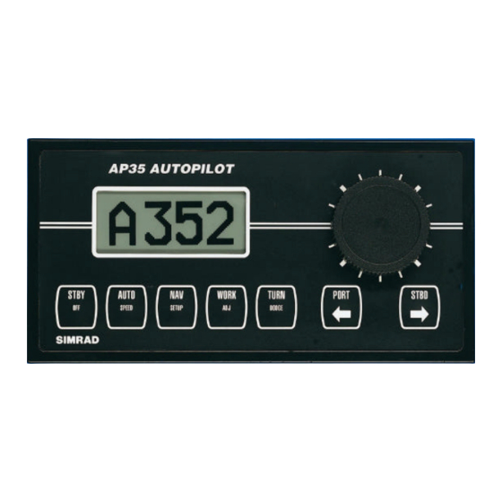
Sign In
Upload
Manuals
Brands
Simrad Manuals
Autopilot System
AP35
Simrad AP35 Manuals
Manuals and User Guides for Simrad AP35. We have
1
Simrad AP35 manual available for free PDF download: Instruction Manual
Simrad AP35 Instruction Manual (104 pages)
Brand:
Simrad
| Category:
Autopilot System
| Size: 2.33 MB
Table of Contents
Table of Contents
5
Instruction Manual
1
1 General Information
11
Introduction
11
How to Use this Manual
11
System Components
12
AP35 Control Unit
12
Figure 1-1 Ap35 Basic System
12
Junction Units
13
Rudder Feedback Units
13
RF300 Rudder Feedback Unit
13
RF45X Rudder Feedback Unit
13
Heading Sensors
13
RFC35 Electronic Fluxgate Compass
13
RC25 Rate Compass
14
CDI35 Course Detector Interface and CD100A (CD109) Course Detector
14
NMEA Compass
14
Other Compass Models
14
Optional Equipment
14
R3000X Remote Control
14
S35 NFU Steering Lever
14
FU50 Follow-Up Steering Lever
14
F1/2 NFU Remote
15
RI35 Mk2 Rudder Angle Indicator
15
2 Operation of the Autopilot
17
Overview
17
Figure 2-1 Ap35 Front Panel
17
ON/OFF - Standby Mode
18
Follow-Up Steering
19
Non-Follow-Up Steering
19
NFU Steering Lever
19
NFU Push Button Remote Control
19
R3000X Remote Control
20
S35 NFU Steering Lever
20
Automatic Steering
21
Automatic Speed Selection
22
Manual Speed Selection
22
Navigating with the AP35
23
Selecting a Different Navigator
24
WORK-Mode
25
TURN-Mode
26
Dodging
27
Dodge in NAV
27
Multiple Station System
27
Lock Function
28
User Set-Up Menu
29
3 Technical Specifications
31
AP35 Autopilot System
31
AP35 Control Unit
32
Junction Units
32
Figure 3-1 Ap35 Control Unit - Dimensions Drw. No. N3-208305
32
Figure 3-2 J300X/J3000X Junction Unit - Dimensions
33
Figure 3-3 J300X-40 Junction Unit - Dimensions
33
RFC35 Fluxgate Compass
34
Figure 3-4 Rfc35 Fluxgate Compass - Dimensions
34
3.5 Rc25 Rate Compass
35
CDI35 Course Detector Interface
35
RC25 Rate Compass
35
Figure 3-5 Ri35 Mk2 Dimensions
36
RI35 Mk2 Rudder Angle Indicator
36
Figure 3-6 Rf300 Rudder Feedback - Dimensions
37
Figure 3-7 Transmission Link - Dimensions
37
RF300 Rudder Feedback Unit
37
Figure 3-8 Rf45X Rudder Feedback Unit
38
Figure 3-9 Rf45 Transmission Link
38
RF45X Rudder Feedback Unit
38
CI300X Compass Interface
39
Figure 3-10 R3000X - Dimensions
39
R3000X Remote
39
Dimensions
40
Environmental Protection
40
Figure 3-11 Ci300X and Ni300X - Dimensions
40
Material
40
Mounting
40
NI300X NMEA Interface
40
Power Consumption
40
S35 NFU Steering Lever
40
Temperature Range
40
Weight
40
F1/2 Remote Control
41
Figure 3-12 S35 - Dimensions
41
Figure 3-13 F1/F2 - Dimensions
41
Environmental Protection
42
Figure 3-14 Fu50 Dimensions
42
FU50 Steering Lever
42
Material
42
Power Consumption
42
Safe Distance to Compass
42
IP Protection
43
4 Installation
45
General
45
Installation Checklist
45
Unpacking and Handling
46
Determine System Configuration
46
AP35 System Layout
47
RF300 Rudder Feedback
47
Figure 4-1 Ap35 System Layout with Options
47
Figure 4-2 Rf300 Mounting (019356)
48
Figure 4-3 Rf300 Connection
48
RF45X Rudder Feedback Unit
49
Figure 4-4 Rf45X Rudder Feedback Unit - Mounting
49
Electrical Connection
50
Figure 4-5 Rf45X Connection
50
Junction Unit
51
Cable Connections
51
Figure 4-6 J3Xx Mounting
51
Grounding and RFI
52
Junction Unit Terminals
52
Figure 4-7 J3Xx - Screen Termination
52
Drive Unit
53
Connecting a Reversible Pump
55
Connecting a Hydraulic Linear Drive
55
Figure 4-8 Connecting a Reversible Pump
55
Figure 4-9 Connecting a Hydraulic Linear Drive
55
Connecting a Solenoid Valve
56
Control Unit
56
Panel Mounting
56
Bracket Mounting
56
Figure 4-10 Connecting a Solenoid Valve
56
Figure 4-11 Ap35 Panel Mounting
56
ROBNET Network Cables
57
Figure 4-12 Ap35 Bracket Mounting
57
Figure 4-13 Control Unit Connection
58
RFC35 Fluxgate Compass
59
Figure 4-14 Rfc35 Mounting
59
RC25 Rate Compass
60
Figure 4-15 Rfc35 Connection
60
Figure 4-16 Rc25 Connection to Ap35 Control Unit
60
R3000X Remote Control
61
FU50 Steering Lever
61
Figure 4-17 R3000X Connection
61
S35 NFU Steering Lever
62
F1/2 Remote Control
62
Figure 4-18 S35 Connection to Junction Unit
62
Figure 4-19 F1/2 Connection
62
RI35 Mk2 Rudder Angle Indicator
63
RI35 Mk2 Illumination
63
Zero Adjust
63
Figure 4-20 Ri35 Mk2-J3000X/J300X Wiring Diagram
63
Reversed Deflection
64
Interfacing
65
Single NMEA Input/Output
65
Double NMEA Input/Output
65
Figure 4-21 Single Nmea Connection
65
Figure 4-22 Double Nmea Connection
65
Additional NMEA Output on Port 2
66
NMEA Compass in
66
Radar Clock/Data
66
Figure 4-23 Nmea Compass Connection
66
Figure 4-24 Radar Clock/Data Connection
66
IS15 Instrument
67
Figure 4-25 Is15 Instruments / J3Xx Connection
67
Figure 4-26 Is15 Expander / J3Xx Connection
67
Analog Repeater
68
Digital Repeater
68
Figure 4-27 Ar77 and Ar68 Analog Repeater Connection
68
Figure 4-28 Dr75 Digital Repeater Connection
68
External Alarm
69
NI300X NMEA Interface Unit
69
Figure 4-29 External Alarm Connection
69
CI300X Analogue Interface Unit
70
Figure 4-30 Ni300X Connection
70
CD100A Course Detector
71
Figure 4-31 Ci300X Connections
71
CDI35 Interface
72
Figure 4-32 Cd100A Mounting
72
Figure 4-33 Cdi35 Connection
72
Software Setup Procedure
73
Description of Installation Settings
73
Installation Settings Menu
74
Language Selection
74
Dockside Settings
75
Figure 4-34 Installation Settings Menu
75
Drive Unit Voltage Selection
76
Alignment for RF45X Rudder Feedback Unit
77
Rudder Feedback Calibration
77
Automatic Rudder Test
79
Transition Speed
79
Autotrim WORK
80
Initial Rudder
80
Master Reset
80
Interface Settings
81
Sea Trial
85
Rudder Zero Adjust
85
Compass Calibration
86
Compass Offset
86
Automatic Tuning
87
View Parameters
88
Manual Parameter Adjust
89
Final Sea Trial
90
Providing User Training
91
5 Maintenance
92
Control Unit
92
Junction Unit
92
Rudder Feedback
92
Compass
92
Drive Unit
92
Exchange of Software Programme
93
Figure 5-1 J3000X/J300X/J300X-40 Main Pc-Board
93
Figure 5-2 Ap35 Pcb, Component Layout
93
Modification on AP35 PCB
94
6 Trouble Shooting
95
Alarms
95
NMEA Test
98
System Data Menu
99
7 Spare Parts List
100
8 Sales and Service Worldwide (300903)
103
Advertisement
Advertisement
Related Products
Simrad ROBERTSON AP45
Simrad AP25
Simrad AP26
Simrad AP27
Simrad AP50
Simrad AP16
Simrad AP28
Simrad AP24
Simrad AP44
Simrad AP70 MK2
Simrad Categories
Marine Equipment
Transducer
Sonar
Accessories
Autopilot System
More Simrad Manuals
Login
Sign In
OR
Sign in with Facebook
Sign in with Google
Upload manual
Upload from disk
Upload from URL