Keithley 2001 Quick Reference Manual
Multimeter
Hide thumbs
Also See for 2001:
- Operator's manual (488 pages) ,
- Repair manual (168 pages) ,
- Calibration manual (107 pages)
Table of Contents
Advertisement
Quick Links
Advertisement
Table of Contents

Subscribe to Our Youtube Channel
Related Manuals for Keithley 2001


Summary of Contents for Keithley 2001
- Page 1 Model 2001 Multimeter Quick Reference Guide...
- Page 2 Model 2001 Multimeter Quick Reference Guide © 1992, Keithley Instruments, Inc. All rights reserved. Cleveland, Ohio 44139 U.S.A. Document Number: 2001-903-01 Rev. B...
-
Page 3: Table Of Contents
Table of Contents Safety Precautions ............1 Introduction ..............5 Operation Summary ............ 6 Multiple Displays ............11 Menu Structures ............13 Default Conditions ............ 32 Error and Status Messages ......... 48 IEEE-488.2 Common Commands and Queries... 56 SCPI Command Subsystems ........58... -
Page 4: Safety Precautions
Safety Precautions The following safety precautions should be observed before using this product and any associated instrumentation. Al- though some instruments and accessories would normally be used with non-hazardous voltages, there are situations where hazardous conditions may be present. This product is intended for use by qualified personnel who recognize shock hazards and are familiar with the safety pre- cautions required to avoid possible injury. - Page 5 As described in the International Electrotechnical Commis- sion (IEC) Standard IEC 664, digital multimeter measuring circuits (e.g., Keithley Models 175A, 199, 2000, 2001, 2002, and 2010) are Installation Category II. All other instruments’ signal terminals are Installation Category I and must not be connected to mains.
- Page 6 Do not touch any object that could provide a current path to the common side of the circuit under test or power line (earth) ground. Always make measurements with dry hands while standing on a dry, insulated surface capable of withstanding the voltage being measured.
- Page 7 (Note that selected parts should be purchased only through Keithley Instruments to maintain ac- curacy and functionality of the product.) If you are unsure about the applicability of a replacement component, call a Keithley Instruments office for information.
-
Page 8: Introduction
This quick reference guide includes summary informa- tion on front panel and IEEE-488 operation for the Model 2001 Multimeter. For detailed information, con- sult the Model 2001 Operator’s Manual, the Model 2001 Calibration Manual, and the Model 2001-SCAN Scanner Card Instruction Manual. -
Page 9: Operation Summary
Operation Summary Default Configuration The Model 2001 can save from one to ten user setups in memory, depending on the installed memory option. You can select one of the user setups as the power-on default, or have the instrument power up to either of the two factory defaults (optimized for “BENCH”... - Page 10 Assuming the Model 2001 is set to primary address 16, the instrument can be reset and the reading displayed on the computer CRT from the IEEE-488 bus with the following code fragment: 100 OUTPUT 716;“:syst:pres” 110 OUTPUT 716;“:fetc?” 120 ENTER 716;A$...
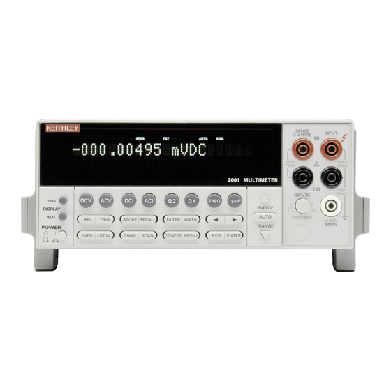
- Page 11 Model 2001 SENSE INPUT Ω 4 WIRE DC Voltage 350V 1100V PEAK PEAK Source 2001 MULTIMETER 500V INPUTS PEAK PREV Ω2 Ω4 FREQ TEMP DISPLAY RANGE NEXT AUTO FRONT/REAR TRIG STORE RECALL FILTER MATH 2A 250V POWER AMPS RANGE INFO...
- Page 12 the DCV configuration menu: CONFIGURE DCV SPEED FILTER RESOLUTION 2. Select SPEED from the menu, then press ENTER. The multimeter displays the following menu: DCV MEASUREMENT SPEED NORMAL FAST MEDIUM HIACCURACY SET-SPEED-EXACTLY SET-BY-RESLN 3. Using the cursor keys, select the FAST option, then press ENTER.
- Page 13 The following code fragment configures the Model 2001 for high speed DC voltage readings, stores 100 readings, and sends the readings over the bus: 100 OUTPUT 716;“:syst:pres”...
-
Page 14: Multiple Displays
Multiple Displays Each measurement function has its own set of “multiple displays” shown on the bottom line of the front panel display. To scroll through the multiple displays available for the present function, repeatedly press and release the NEXT DISPLAY key. The same action with the PRE- Vious DISPLAY key does a reverse scroll through the displays. - Page 15 Table 1. Multiple displays by function (cont.) Function Next display Temperature Celsius, Fahrenheit, and Kelvin units RTD resistance (or thermocouple voltage) Reference junction (thermocouples only) Data storage buffer Maximum and minimum values Average and standard deviation Notes: 1. Multiple displays for calculated values and limits bar graph are not available for the frequency function.
-
Page 16: Menu Structures
Menu Structures The desired menu is displayed by pressing the appropri- ate key or sequence: • CONFIG and then DCV (or ACV, DCI, ACI, Ω 2, Ω 4, FREQ, TEMP) Shows the configuration menu for each measurement function. • CONFIG and then NEXT DISPLAY (or PREV DIS- PLAY, REL, TRIG, STORE, FILTER, MATH, CHAN, SCAN) ... - Page 17 Table 2. CONFIGURE DCV menu structure (cont.) Menu item Description FILTER Digital filter menu: AUTO Default to filter appropriate for integration time. AVERAGING Program a simple average filter (1-100 readings). ADVANCED Program a simple average filter (1-100 readings) with a noise tol- erance window (0-100% of range).
- Page 18 Table 3. CONFIGURE ACV menu structure (cont.) Menu item Description RESOLUTION Display resolution menu: AUTO Default to resolution appropriate for integration time. 3.5d, 4.5d, 5.5d, 6.5d, Select a specific resolution. 7.5d UNITS Display units menu: VOLTS Select volts. Select dB and set voltage reference level.
- Page 19 Table 4. CONFIGURE DCI menu structure Menu item Description SPEED Measurement speed (integration time) menu: NORMAL Select 1 PLC (power line cycle, 16.67msec for 60Hz, 20msec for 50Hz and 400Hz). FAST Select 0.01 PLC. MEDIUM Select 0.1 PLC. HIACCURACY Select 10 PLC. SET-SPEED-EXACTLY Set integration time in PLC (0.01-10).
- Page 20 Table 5. CONFIGURE ACI menu structure Menu item Description SPEED Measurement speed (integration time) menu: NORMAL Select 1 PLC (power line cycle, 16.67msec for 60Hz, 20msec for 50Hz and 400Hz). FAST Select 0.01 PLC. MEDIUM Select 0.1 PLC. HIACCURACY Select 10 PLC. SET-SPEED-EXACTLY Set integration time in PLC (0.01-10).
- Page 21 Table 6. CONFIGURE OHMS-2W menu structure Menu item Description SPEED Measurement speed (integration time) menu: NORMAL Select 1 PLC (power line cycle, 16.67msec for 60Hz, 20msec for 50Hz and 400Hz). FAST Select 0.01 PLC. MEDIUM Select 0.1 PLC. HIACCURACY Select 10 PLC. SET-SPEED-EXACTLY Set integration time in PLC (0.01-10).
- Page 22 Table 7. CONFIGURE OHMS-4W menu structure Menu item Description SPEED Measurement speed (integration time) menu: NORMAL Select 1 PLC (power line cycle, 16.67msec for 60Hz, 20msec for 50Hz and 400Hz). FAST Select 0.01 PLC. MEDIUM Select 0.1 PLC. HIACCURACY Select 10 PLC. SET-SPEED-EXACTLY Set integration time in PLC (0.01-10).
- Page 23 Table 8. CONFIGURE FREQUENCY menu structure Menu item Description MAX-SIGNAL-LEVEL Display maximum signal level menu: 1V, 10V, 100V, 1000V, TTL Select maximum voltage level for voltage inputs. 1mA, 10mA, 100mA, 1A Select maximum current level for current inputs. RESOLUTION Display resolution menu: 4-DIGITS, 5-DIGITS Select a specific resolution.
- Page 24 Table 9. CONFIG TEMPERATURE menu structure Menu item Description SENSOR Sensor type menu: 4-WIRE-RTD 4-wire RTD type menu: PT385 Select a PT385 type. PT3916 Select a PT3916 type. USER-RTD Select desired R-zero, alpha, beta, and delta. 2-wire RTD type menu: PT385 Select a PT385 type.
- Page 25 Table 9. CONFIG TEMPERATURE menu structure (cont.) Menu item Description FILTER Digital filter menu: AUTO Default to filter appropriate for integration time. AVERAGING Select simple average filter (1-100 readings). AVERAGING-MODE Select moving average or repeating average mode. RESLN Display resolution menu: AUTO Default to resolution appropri- ate for sensor.
- Page 26 Table 10. CONFIGURE TRIGGER menu structure Menu item Description MEASURE Measure layer menu: SOURCE Select measure source: IMMEDIATE Use to make measure- ments immediately. EXTERNAL Use external triggers to control measuring. MANUAL Use TRIG key to control measuring. GPIB Use bus triggers to control measuring.
- Page 27 Table 10. CONFIGURE TRIGGER menu structure (cont.) Menu item Description SCAN Scan layer menu: SOURCE Select scan source: IMMEDIATE Use to pass operation immediately into the measure layer. EXTERNAL Use external triggers to control scanning. MANUAL Use TRIG key to control scanning.
- Page 28 Table 10. CONFIGURE TRIGGER menu structure (cont.) Menu item Description Arm layer menu: SOURCE Select arm source: IMMEDIATE Use to arm meter immedi- ately and pass operation into the scan layer. EXTERNAL Use external triggers to arm meter. MANUAL Use TRIG key to arm meter.
- Page 29 Table 11. CONFIG DATA STORE menu structure Menu item Description BURST-MODE Acquire 4.5-digit readings at 2000 readings/sec and store in buffer. DATA-GROUP Select data types to store in buffer. FULL Store reading, units, channel#, read- ing#, time-stamp, and status (overflow). COMPACT Store reading, units, reading#, and status (overflow).
- Page 30 Table 12. CONFIG FILTER menu structure Menu item Description AUTO Default to filter appropriate for measure- ment function and type. AVERAGING Program simple average filter (1-100 read- ings). ADVANCED Program simple average filter (1-100 read- ings), with a noise tolerance window (0-100% of range).
- Page 31 Table 15. CONFIGURE CHANNELS menu structure Menu item Description INTERNAL-CHANS Defines internal functions: SET INTERNAL CHANS Use range and cursor keys 1=DCV 2=DCV 3=DCV to select channels and 4=DCV 5=DCV functions. EXTERNAL INPUTS Sets number of external channels and functions: # EXTERNAL INPUTS=80 # of external channels (1- 80).
- Page 32 SAVESETUP Setup menu: SAVE Save setup at a memory location (up to 1, 5, or 10). RESTORE Return 2001 to setup stored at a memory location (up to 1, 5, or 10). POWERON Power-on Menu: BENCH Power on to bench default setup conditions.
- Page 33 Table 17. Main menu structure (cont.) Menu item Description GPIB GPIB/Printer Setup menu: ADDRESSABLE Check/change IEEE-488 bus address (0-30). TALK-ONLY GPIB/Printer Talk-only mode menu: FEED GPIB Output Feed menu: AFTER-CALC Specify reading after math operation. BEFORE-CALC Specify reading before math operation.
- Page 34 Table 17. Main menu structure (cont.) Menu item Description LIMITS Limits menu: LIMIT-SET-1 Limit-Set-1 menu: CONTROL Enable/disable limit set #1. LOLIM1 Set value of low limit #1. HILIM1 Set value of high limit #1. LIMIT-SET-2 Limit-Set-2 menu: CONTROL Enable/disable limit set #2. LOLIM2 Set value of low limit #2.
-
Page 35: Default Conditions
Default Conditions Table 18. Factory default conditions Function or operation Bench default GPIB default AC current: AC-type Coupling Filter Auto Averaging Readings Advanced Readings Noise tolerance level Filter mode Moving Repeat Range Auto Auto Relative Value Auto (5.5d) Resolution Auto (5.5d) Speed Normal (1 PLC) Normal (1 PLC) - Page 36 Table 18. Factory default conditions (cont.) Function or operation Bench default GPIB default Buffer: Burst mode No effect No effect Control No effect No effect Count No effect No effect Data group No effect No effect Feed No effect No effect DC current: Filter Auto...
- Page 37 Table 18. Factory default conditions (cont.) Function or operation Bench default GPIB default Frequency: Relative Value Resolution Auto (5d) Auto (5d) Terminals Voltage Voltage Trigger level Function Limits: Limit set #1 Low limit #1 -1.0 -1.0 Low limit #1 action High limit #1 High limit #1 action Limit set #2...
- Page 38 Table 18. Factory default conditions (cont.) Function or operation Bench default GPIB default Resistance (4-wire): Filter Auto Averaging Readings Advanced Readings Noise tolerance level Filter mode Moving Repeat Offset compensation Range Auto Auto 200k Ω 200k Ω Maximum autorange Relative Value Resolution Auto (6.5d)
- Page 39 Table 18. Factory default conditions (cont.) Function or operation Bench default GPIB default Temperature: Filter Auto Averaging Readings Filter mode Moving Repeat Relative Value Resolution Auto (0.01°C) Auto (0.01°C) RTDs: Type PT385 PT385 100 Ω 100 Ω Resistance at 0°C Alpha 0.00385 0.00385...
- Page 40 Table 18. Factory default conditions (cont.) Function or operation Bench default GPIB default Triggers: Armed Idled Arm layer: Source Immediate Immediate Triglink input Line 2 Line 2 Triglink output Line 1 Line 1 Count Control Acceptor Acceptor Scan layer: Source Immediate Immediate Triglink input...
- Page 41 Table 19. *RST and :SYSTem:PRESet Command *RST :SYSTem:PRESet IEEE 488.2 common commands All commands [unaffected] [unaffected] SCPI signal oriented commands :CONFigure “VOLT:DC” “VOLT:DC” Calculate 1 subsystem :CALCulate1 :STATe 0 (OFF) 0 (OFF) :FORMat PERCent PERCent :MMFactor :MBFactor :PERCent Calculate 2 subsystem :CALCulate2 :STATe 0 (OFF)
- Page 42 Table 19. *RST and :SYSTem:PRESet (cont.) Command *RST :SYSTem:PRESet :CALCulate3 :BSTRobe :STATe 0 (OFF) 0 (OFF) :PASS :SOURce Calibration subsystem All commands [unaffected] [unaffected] Display subsystem :DISPlay :SMESsage 0 (OFF) 0 (OFF) :WINDow1 :TEXT :STATe [unaffected] [unaffected] :DATA [unaffected] [unaffected] :WINDow2 :TEXT :STATe...
- Page 43 Table 19. *RST and :SYSTem:PRESet (cont.) Command *RST :SYSTem:PRESet :ROUTe :SCAN :RATio :RCHannel :MCHannel :FUNCtion “VOLT:DC” “VOLT:DC” :DELTa :RCHannel :MCHannel :FUNCtion “VOLT:DC” “VOLT:DC” :LSELect NONE NONE Sense commands :SENSe1 :FUNCtion “VOLT:DC” “VOLT:DC” AC current commands :SENSe1 :CURRent :APERture 1/LineFreq 1/LineFreq :AUTO 0 (OFF) 0 (OFF)
- Page 44 Table 19. *RST and :SYSTem:PRESet (cont.) Command *RST :SYSTem:PRESet DC current commands :SENSe1 :CURRent :APERture 1/LineFreq 1/LineFreq :AUTO 0 (OFF) 0 (OFF) :NPLCycles :AUTO 0 (OFF) 0 (OFF) :RANGe :UPPer :AUTO 1 (ON) 1 (ON) :ULIMit :LLIMit 2.0E-4 2.0E-4 :REFerence :STATe 0 (OFF) 0 (OFF)
- Page 45 Table 19. *RST and :SYSTem:PRESet (cont.) Command *RST :SYSTem:PRESet :SENSe1 :VOLTage :DIGits :AUTO 1 (ON) 1 (ON) :AVERage :STATe 0 (OFF) 0 (OFF) :AUTO 0 (OFF) 1 (ON) :COUNt :TCONtrol REPeat MOVing :ADVanced :STATe 1 (ON) 1 (ON) :NTOLerance :DETector :FUNCtion DC voltage commands :SENSe1:...
- Page 46 Table 19. *RST and :SYSTem:PRESet (cont.) Command *RST :SYSTem:PRESet Frequency commands :SENSe1 :FREQuency :COUPling :REFerence :STATe 0 (OFF) 0 (OFF) :DIGits :THReshold :VOLTage :LEVel :RANGe :CURRent :LEVel :RANGe 1.0E-3 1.0E-3 :SOURce VOLTage VOLTage 2-wire resistance commands :SENSe1 :RESistance :APERture 1/LineFreq 1/LineFreq :AUTO 0 (OFF)
- Page 47 Table 19. *RST and :SYSTem:PRESet (cont.) Command *RST :SYSTem:PRESet 4-wire resistance commands :SENSe1 :FRESistance :APERture 1/LineFreq 1/LineFreq :AUTO 0 (OFF) 0 (OFF) :NPLCycles :AUTO 0 (OFF) 0 (OFF) :RANGe :UPPer 2.1E+5 2.1E+5 :AUTO 1 (ON) 1 (ON) :ULIMit 2.1E+5 2.1E+5 :LLIMit :REFerence :STATe...
- Page 48 Table 19. *RST and :SYSTem:PRESet (cont.) Command *RST :SYSTem:PRESet :SENSe1 :TEMPerature :RJUNction1 :SIMulated 23(˚C) 23(˚C) :REAL :TCOefficient 0.01 0.01 :OFFSet 0.01 0.01 :RJUNction2 :RSELect SIMulated SIMulated :SIMulated 23(˚C) 23(˚C) :REAL :TCOefficient 0.01 0.01 :OFFSet 0.01 0.01 :RJUNction3 :RSELect SIMulated SIMulated :SIMulated 23(˚C) 23(˚C)
- Page 49 Table 19. *RST and :SYSTem:PRESet (cont.) Command *RST :SYSTem:PRESet System subsystem :SYSTem :KEY [unaffected] [unaffected] :AZERo :STATe 1 (ON) 1 (ON) :TYPE NORMal NORMal :LSYNc :STATe 0 (OFF) 0 (OFF) :POSetup [unaffected] [unaffected] :AMEThod NORMal NORMal :FETCh :FORMat [unaffected] [unaffected] Trigger subsystem :INITiate :CONTinuous...
- Page 50 Table 19. *RST and :SYSTem:PRESet (cont.) Command *RST :SYSTem:PRESet :TRIGger :SEQuence1 :TCONfigure :ASYNchronous :ILINe :OLINe :SSYNchronous :LINE Status subsystem All commands [unaffected] [unaffected] Trace subsystem All commands [unaffected] [unaffected] Unit commands :UNIT :TEMPerature :VOLTage :REFerence :DBM :IMPedance...
-
Page 51: Error And Status Messages
Error and Status Messages Table 20. Error and status messages Number Description Event +900 “Internal System Error” +611 “Questionable Temperature” +610 “Questionable Calibration” +515 “Calibration dates lost” +514 “DC calibration data lost” +513 “AC calibration data lost” +512 “Power-on state lost” +511 “GPIB address lost”... - Page 52 Table 20. Error and status messages (cont.) Number Description Event SE = Status event EE = Error event -100 “Command Error” -101 “Invalid Character” -102 “Syntax Error” -103 “Invalid Separator” -104 “Data Type Error” -105 “GET not allowed” -108 “Parameter not allowed” -109 “Missing Parameter”...
- Page 53 Table 20. Error and status messages (cont.) Number Description Event -210 “Trigger error” -211 “Trigger ignored” -212 “Arm ignored” -213 “Init ignored” -214 “Trigger deadlock” -215 “Arm deadlock” -220 “Parameter Error” -221 “Settings conflict” -222 “Parameter data out of range” -223 “Too much data”...
- Page 54 Figure 2. Standard event status...
- Page 55 Figure 3. Operation event status...
- Page 56 Figure 4. Measurement event status...
- Page 57 Figure 5. Questionable event status...
- Page 58 Figure 6. Status byte and service request (SRQ)
-
Page 59: Ieee-488.2 Common Commands And Queries
*OPT? Option identifica- Reads ID code of options tion query present (memory, scanner). *RCL <NRf> Recall command Returns the 2001 to the setup configuration stored in the designated memory location. *RST Reset command Returns the 2001 to the *RST default conditions. - Page 60 Table 21. IEEE-488.2 common commands and queries (cont.) Mnemonic Name Description *SRE? Service request Reads Service Request enable query Enable Register. *STB? Read status byte Reads Status Byte Register. query *TRG Trigger command Issues a bus trigger. *TST? Self-test query Performs a checksum test on ROM and return the results.
-
Page 61: Scpi Command Subsystems
Table 22. Signal oriented measurement commands Command Description :FETCh? Requests the latest reading (SCPI) or a fresh reading (FRESh). :CONFigure:<function> Places the 2001 in a “one-shot” mea- surement mode for the specified func- tion. :READ? Performs an :ABORt, :INITiate, and a FETCh?. :MEASure[:<function>]? Performs an :ABORt, :CONFigure :<function>, and a :READ?. - Page 62 Table 23. Calculate command summary (cont.) Command Description :CALCulate[1] :KMATh :MBFactor? Query “b” factor. :PERCent <NRf> Set PERCENT value (-9.999999e35 to +9.999999e35). :PERCent? Query PERCENT. :STATe <b> Enable (1 or ON) or disable (0 or OFF) calculation. :STATe? Query state of math function. :DATA? Read math result of CALC 1.
- Page 63 Table 23. Calculate command summary (cont.) Command Description :CALCulate3 :LIMit[1] :CLEAR [:IMMediate] Clear failed test indication. :AUTO <b> Enable (1 or ON) or disable (0 or OFF) auto clear. :AUTO? Query auto clear. :LIMit2 Path to control LIMIT 2 test: :UPPer Path to configure upper limit: [:DATA] <n>...
- Page 64 :SAVE Save cal constants to EEPROM. :DATA? Download cal constants from 2001. :DATE “<string>” Send cal date to 2001. :DATE? Request cal date from 2001. :NDUE “<string>” Send next due cal date to 2001. :NDUE? Request next due cal date from 2001.
- Page 65 Table 24. CALibrate command summary (cont.) Command Description :CALibration :PROTected User calibration subsystem. :ZERO Low-thermal short calibra- tion step. :LOW <NRf> +2V DC calibration step. :HIGH <NRf> +20V DC calibration step. :LOHM <NRf> 20kΩ calibration step. :HOHM <NRf> 1MΩ calibration step. :OPEN Open circuit calibration step.
- Page 66 Table 25. DISPlay command summary (cont.) Command Description :DISPlay :CNDisplay Clear NEXT (or PREV) display messages and cancel associated operations. :SMESsage <b> Enable (1 or ON) or disable (0 or OFF) status message mode. :SMESsage? Query status message mode (0 or 1). :ENABle <b>...
- Page 67 Table 27. OUTPut command summary Command Description :OUTPut :TTL[1] Path to set polarity of digital out- put line 1: :LSENse <name> Select polarity; active (AHIGH) or active (ALOW). :LSENse? Query polarity of line 1. :TTL2 Path to set polarity of digital out- put line 2: :LSENse <name>...
- Page 68 Table 28. ROUTe command summary (cont.) Command Description :ROUTe :SCAN [:INTernal]? Query the internal scan list. :FUNCtion <list>, Assign measurement function <name> to specified channels. :FUNCtion? <list> Query function for each speci- fied channel. :EXTernal <list> Specify an external scan list (2 to 80 channels).
- Page 69 Table 29. Sense command summary Command Description [:SENSe[1]] :ALTernate[1] Path to control an Alternate setup. :SAVE Save current setup as Alternate setup. :RECall Return instrument to Alternate setup. :FUNCtion <name> Select measurement function: ‘VOLTage:AC’, ‘VOLTage: DC’,‘RESistance’, ‘FRESis- tance’,‘CURRent:AC’, ‘CUR- Rent:DC’,‘FREQuency’, ‘TEMPerature’...
- Page 70 Table 29. Sense command summary (cont.) Command Description :CURRent:AC Path to configure AC current. :APERture <n> Specify integration rate in sec- onds (166.67e-6 to 200e-3). :AUTO <b> Enable (1 or ON) or disable (0 or OFF) auto aperture. :AUTO ONCE Enable and then disable auto aperture.
- Page 71 Table 29. Sense command summary (cont.) Command Description :CURRent:AC :RANGe :AUTO ONCE Set range based on present input signal. :ULIMit <n> Specify upper limit for auto range (0 to +2.1). :ULIMit? Query upper limit. :LLIMit <n> Specify lower limit for auto range (0 to +2.1).
- Page 72 Table 29. Sense command summary (cont.) Command Description :CURRent:AC :AVERage :ADVanced [:STATe]? Query state of advanced filter. [:STATe] <b> Enable (1 or ON) or disable (0 or OFF) filter. [:STATe]? Query state of digital filter. :AUTO <b> Enable (1 or ON) or disable (0 or OFF) auto filter.
- Page 73 Table 29. Sense command summary (cont.) Command Description :CURRent:DC :RANGe :AUTO ONCE Set range based on present input signal. :ULIMit <n> Specify upper limit for auto range (0 to 2.1). :ULIMit? Query upper limit. :LLIMit <n> Specify lower limit for auto range (0 to 2.1).
- Page 74 Table 29. Sense command summary (cont.) Command Description :CURRent:DC :AVERage :ADVanced [:STATe]? Query state of advanced filter. [:STATe] <b> Enable (1 or ON) or disable (0 or OFF) filter. [:STATe]? Query state of digital filter. :AUTO <b> Enable (1 or ON) or disable (0 or OFF) auto filter.
- Page 75 Table 29. Sense command summary (cont.) Command Description :VOLTage:AC :RANGe :AUTO <b> Enable (1 or ON) or disable (0 or OFF) auto range. :AUTO ONCE Set range based on present input signal. :ULIMit <n> Specify upper limit for auto range (0 to +775). :ULIMit? Query upper limit.
- Page 76 Table 29. Sense command summary (cont.) Command Description :VOLTage:AC :AVERage :ADVanced [:STATe] <b> Enable (1 or ON) or dis- able (0 or OFF) advanced filter. [:STATe]? Query state of advanced filter. [:STATe] <b> Enable (1 or ON) or disable (0 or OFF) filter. [:STATe]? Query state of digital filter.
- Page 77 Table 29. Sense command summary (cont.) Command Description :VOLTage:DC :NPLCycles <n> :AUTO? Query auto line cycle inte- gration (0 or 1). :NPLCycles? Query line cycle integration rate. :RANGe Path to configure measure- ment range: [:UPPer] <n> Select range (0 to 1100). [:UPPer]? Query range.
- Page 78 Table 29. Sense command summary (cont.) Command Description :VOLTage:DC :AVERage :ADVanced Path to configure and con- trol advanced filter. :NTOLerance <n> Specify noise tolerance level (0 to 100 percent). :NTOLerance? Query noise tolerance level. [:STATe] <b> Enable (1 or ON) or dis- able (0 or OFF) advanced filter.
- Page 79 Table 29. Sense command summary (cont.) Command Description :RESistance :RANGe [:UPPer] <n> Select range (0 to 1.05e9). [:UPPer]? Query range. :AUTO <b> Enable (1 or ON) or disable (0 or OFF) auto range. :AUTO ONCE Set range based on present input signal.
- Page 80 Table 29. Sense command summary (cont.) Command Description :RESistance :AVERage :ADVanced :NTOLerance? Query noise tolerance level. [:STATe] <b> Enable (1 or ON) or dis- able (0 or OFF) advanced filter. [:STATe]? Query state of advanced filter. [:STATe] <b> Enable (1 or ON) or disable (0 or OFF) filter.
- Page 81 Table 29. Sense command summary (cont.) Command Description :FRESistance :RANGe Path to configure measure- ment range: [:UPPer] <n> Select range (0 to 2.1e5). [:UPPer]? Query range. :AUTO <b> Enable (1 or ON) or disable (0 or OFF) auto range. :AUTO ONCE Set range based on present input signal.
- Page 82 Table 29. Sense command summary (cont.) Command Description :FRESistance :AVERage :ADVanced :NTOLerance? Query noise tolerance level. [:STATe] <b> Enable (1 or ON) or dis- able (0 or OFF) advanced filter. [:STATe]? Query state of advanced filter. [:STATe] <b> Enable (1 or ON) or disable (0 or OFF) filter.
- Page 83 Table 29. Sense command summary (cont.) Command Description :FREQuency :THReshold :CURRent :LEVel <n> Specify threshold level. :LEVel? Query threshold level. :VOLTage Path to set voltage thresh- old: :RANGe <n> Specify range (0 to 1000). :RANGe? Query range. :LEVel <n> Specify threshold level. :LEVel? Query threshold level.
- Page 84 Table 29. Sense command summary (cont.) Command Description :TEMPerature :DIGits <n> Specify measurement resolu- tion (4 to 7). :AUTO <b> Enable (1 or ON) or disable (0 or OFF) auto resolution. :AUTO ONCE Enable and then disable auto resolution. :AUTO? Query auto resolution (0 or :DIGits? Query resolution.
- Page 85 Table 29. Sense command summary (cont.) Command Description :TEMPerature :TCouple Path to configure TC measure- ments: :TYPE <name> Select thermocouple type: J, T, K, E, R, S, B. :TYPE? Query TC type. :RJUNctionX Path to configure reference junctions (Z = 1 to 5). :RSELect <name>...
- Page 86 Table 30. SOURce command summary Command Description :SOURce :TTL[1][:LEVel] <b> Set digital output line #1 true (1 or ON) or false (0 or OFF). :TTL[1][:LEVel]? Query digital output line 1. :TTL2[:LEVel] <b> Set digital output line #2 true (1 or ON) or false (0 or OFF).
- Page 87 Table 31. STATus command summary (cont.) Commands Description :STATus :OPERation :NTRansition <NRf> Program the negative transi- tion register. :NTRansition? Read the negative transition register. :CONDition? Read the condition register. :ARM Path to control arm event registers: [:EVENt]? Read the event register. :ENABle <NRf>...
- Page 88 Table 31. STATus command summary (cont.) Commands Description :STATus :OPERation :TRIGger :ENABle? Read the enable register. :PTRansition <NRf> Program the positive tran- sition register. :PTRansition? Read the positive transi- tion register. :NTRansition <NRf> Program the negative tran- sition register. :NTRansition? Read the negative transi- tion register.
- Page 89 Table 32. SYSTem command summary Command Description :SYSTem :PRESet Return to :SYST:PRES defaults. :POSetup <name> Select power-on setup: RST, PRE- Set, SAV0-SAV9. :POSetup? Query power-on setup. :FRSWitch? Query INPUTS switch (0 = rear, 1 = front). :VERSion? Query revision level of SCPI stan- dard.
- Page 90 Table 33. TRACe command summary Command Description :TRACe|:DATA Use :TRACe or :DATA as root command. :CLEar [BUFFER,] Clear readings from buffer. :FREE? [BUFFER,] Query bytes available and bytes in use. :EGRoup [BUFFER,] <name> Select element group: FULL, COMPact. :EGRoup? [BUFFER,] Query element group.
- Page 91 Table 34. Trigger command summary Command Description :INITiate Subsystem command path: [:IMMediate] Initiate one trigger cycle. :CONTinuous <b> Enable (1 or ON) or disable (0 or OFF) continuous initiation of trigger system. :CONTinuous? Query continuous initiation. :ABORt Reset trigger system. :ARM[:SEQuence[1]] Subsystem command path to con- figure arm layers:...
- Page 92 Table 34. Trigger command summary (cont.) Command Description :ARM[:SEQuence[1]] :LAYer2 :TCONfigure Path to configure Triggers: :DIRection <name> Enable (SOUR) or disable (ACC) Bypass: SOURce, ACCeptor. :DIRection? Query direction. :ASYNchronous Path to configure asynchro- nous Trigger Link: :ILINe <NRf> Select input line (1 to 6). :ILINe? Query input line.
- Page 93 Table 34. Trigger command summary (cont.) Command Description :TRIGger[:SEQuence[1]] :TCONfigure :SSYNchronous Path to configure semi-syn- chronous Trigger Link: :LINE <NRf> Select trigger line (1 to 6). :LINE? Query trigger line. Table 35. UNIT command summary Command Description :UNIT :TEMPerature <name> Select temperature measurement units: C, CEL, F, FAR, K.
- Page 94 Keithley Instruments, Inc. 28775 Aurora Road Cleveland, Ohio 44139 Printed in the U.S.A.
Need help?
Do you have a question about the 2001 and is the answer not in the manual?
Questions and answers