
Subscribe to Our Youtube Channel
Related Manuals for SCIFIT STEP ONE


Summary of Contents for SCIFIT STEP ONE
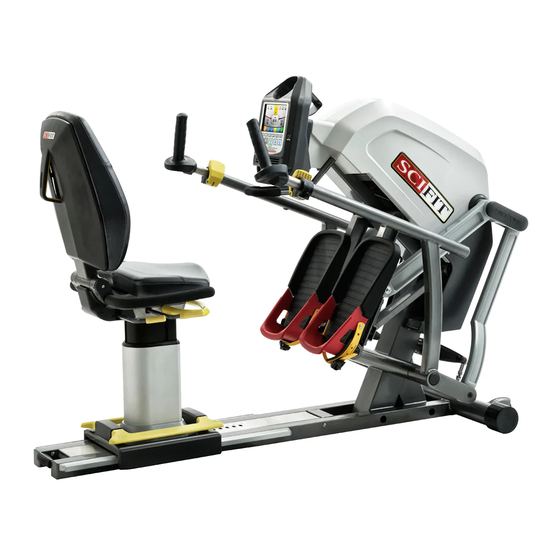
- Page 1 Service Manual RECUMBENT STEPPER Before Using this product, read this manual and follow all safety rules and operating instructions.
-
Page 2: Table Of Contents
LEFT/RIGHT FOOT PEDALS........63- 64 SCIFIT... -
Page 3: Table Of Contents
EXPLODED VIEW..........81 - 98 MAINTENANCE/CONTACT INFORMATION....... 99 SCIFIT Scientific Solutions For Fitness... - Page 4 CAUTION WARNINg ATTENTION Read all instructions before doing service on a SCIFIT exercise machine. Save these instructions for future reference. Close supervision is necessary when doing service on the exercise machine by or near children or individuals with disabilities. Keep children away from the machine when being serviced.
- Page 5 Heart Rate, Stress Test and Random Accuracy Class Class A Warranty Within U.S. & Canada: 5 years parts, 1 year labor Outside U.S.: 5 years parts, no labor 766mm 30in 1742mm 69in 1220mm 48in SCIFIT Scientific Solutions For Fitness SCIFIT Scientific Solutions For Fitness SCIFIT...
- Page 6 The left and right instructions pertain as if the user in a location that is away from walking traffic to is sitting on the machine facing the console. avoid injury to yourself and others. SCIFIT Scientific Solutions For Fitness SCIFIT Scientific Solutions For Fitness...
- Page 7 TO REMOUNT: Repeat steps 1 and 2 in reverse to place the seat assembly back onto the machine. SCIFIT Scientific Solutions For Fitness SCIFIT Scientific Solutions For Fitness...
- Page 8 * 3/16 T-Handle Allen Hex * Small Deadblow Hammer * Narrow Edge Plastic Punch Step 1: Use a 3/16 allen hex to remove the dog point set screw (#25903) SCIFIT Scientific Solutions For Fitness SCIFIT Scientific Solutions For Fitness SCIFIT...
-
Page 9: Step
Step 3b: Continue to turn the thumb nut until it comes completely off of the threaded rod, then remove the lever clamp (#A5137)/ threaded rod (#A5407) and clamp barrel (#A5408). SCIFIT Scientific Solutions For Fitness SCIFIT Scientific Solutions For Fitness SCIFIT... - Page 10 Step 6a: Push the tabs of handlbar inner tube end plug (#A5134) inward to dislodge it from PUSH TABS the handlebar tube. INWARD SCIFIT Scientific Solutions For Fitness SCIFIT Scientific Solutions For Fitness SCIFIT...
- Page 11 Step 7: Slide the clamp sleeve completely off of the handlebar tube. SPECIFICATIONS rIghT hAnDLEBAr rEmovAL Follow the steps in the “Left handlebar Removal” section for the right handlebar (#A5170). SCIFIT Scientific Solutions For Fitness SCIFIT Scientific Solutions For Fitness SCIFIT...
- Page 12 Step 2: Align the tabs of the inner tube end plug and insert it into the end of the tube, making sure the tabs pop up through the open holes. SCIFIT Scientific Solutions For Fitness SCIFIT Scientific Solutions For Fitness SCIFIT...
- Page 13 Gently tap the sleeve clamp until the lip of the sleeve is flush with the outer tube edge making sure the sleeve clamp and angle indicator clamp holes are aligned. ALIGN HOLES SCIFIT Scientific Solutions For Fitness SCIFIT Scientific Solutions For Fitness SCIFIT...
- Page 14 3/16 allen hex to reinsert it into the handlebar tube. Step 8: Reattach the lever clamp, threaded rod, clamp barrel and thumb nut previously removed. SCIFIT Scientific Solutions For Fitness SCIFIT Scientific Solutions For Fitness SCIFIT...
- Page 15 Using a separation tool, place the tool in between the angle clamp’s (#A5135) opening and separate, so the alignment tabs of the clamp are dislodged from the tube hole opening. SCIFIT Scientific Solutions For Fitness SCIFIT Scientific Solutions For Fitness SCIFIT...
- Page 16 LEFT AngLE InDIcATor cLAmp rEpLAcEmEnT Tools Required: * Angle Clamp Separation Tool Step 1: Position the new angle indicator clamp as shown in the drawing, so the “+30” is on the right side. SCIFIT Scientific Solutions For Fitness SCIFIT Scientific Solutions For Fitness SCIFIT...
- Page 17 Follow the “Left Angle Indicator Clamp Replacement” steps for the right side. Note: When replacing the right side verify the “+30” is on the left as shown in the diagram. SCIFIT Scientific Solutions For Fitness SCIFIT Scientific Solutions For Fitness...
- Page 18 Place a 5/8” socket on the lock nut and a 1/4” allen hex on the screw head that secures the hardware, lower outer handle 5/8” Socket and link assembly. 1/4” Allen Hex SCIFIT Scientific Solutions For Fitness SCIFIT Scientific Solutions For Fitness SCIFIT...
- Page 19 The outer handle cover cap (#A5435) has a small opening so the end of a flat head screwdriver may fit into it. Use a small flat head screwdriver to pop out the cap. SCIFIT Scientific Solutions For Fitness SCIFIT Scientific Solutions For Fitness...
- Page 20 (#10537-08102) and (b) 3/8-16 x 1” black socket button head screw (#10537-08099) . Step 8: Grab the outer handle assembly (#A5433) and carefully pull it off of the machine shaft. SCIFIT Scientific Solutions For Fitness SCIFIT Scientific Solutions For Fitness SCIFIT...
- Page 21 Carefully place the new outer handle onto the frame shaft. Step 2: Place a small amount of Loctite 271 onto the threads of the screw, then loosely attach the screw and flat washer previously removed. SCIFIT Scientific Solutions For Fitness SCIFIT Scientific Solutions For Fitness SCIFIT...
- Page 22 Secure the pivot link and the assembly link to the lower outer handle with a 1/4” allen hex and a torque wrench set at 720 in/lbs. 5/8” Socket 1/4” Allen Hex SCIFIT Scientific Solutions For Fitness SCIFIT Scientific Solutions For Fitness SCIFIT...
- Page 23 Use the tools and follow the steps of the “Left Handlebar Replacement” section (pages 9 thru 12). rIghT oUTEr hAnDLE ASSEmBLy rEpLAcEmEnT SPECIFICATIONS Follow the steps in the “Left Outer handle Assembly Replacement” section for the right outer handle #A5434. SCIFIT Scientific Solutions For Fitness SCIFIT Scientific Solutions For Fitness SCIFIT...
- Page 24 (#10357-03641) a nd (c) 7/16-14 x 4.5” black flat head socket (B) x 4 screw (#10537-08048). Note: The assembly link may swing downward. if so rest it on the towel. SCIFIT Scientific Solutions For Fitness SCIFIT Scientific Solutions For Fitness SCIFIT...
-
Page 25: Pivot Blade
(#10537-03641), (C) pivot link (#A5474) and (D) nylock nut (#1137027). SPECIFICATIONS rIghT pIvoT LInk rEmovAL Follow the steps in the “Left Pivot Link Removal” section for the right pivot link #A5474. SCIFIT Scientific Solutions For Fitness SCIFIT Scientific Solutions For Fitness SCIFIT... - Page 26 Note: Verify the washers are placed in the correct location. SCIFIT Scientific Solutions For Fitness SCIFIT Scientific Solutions For Fitness SCIFIT...
- Page 27 720 in/lbs with 5/8” Socket a 5/8” socket attached. rIghT pIvoT LInk rEpLAcEmEnT SPECIFICATIONS Follow the steps in the “Left Pivot Link Replacement” section for the right pivot link #A5474. SCIFIT Scientific Solutions For Fitness SCIFIT Scientific Solutions For Fitness SCIFIT...
- Page 28 Place a towel on the front leg of the frame and lay the upper part of pivot link on the towel. Step 3: Repeat steps 2 and 3 for the right side pivot link. SCIFIT Scientific Solutions For Fitness SCIFIT Scientific Solutions For Fitness SCIFIT...
- Page 29 Remove the 3/8” black flat washer (#10537-08102) and 3/8-16 x 1” black socket button head screw (#10537-08099). Step 6: Grab the pivot blade and carefully remove it off the shaft. SCIFIT Scientific Solutions For Fitness SCIFIT Scientific Solutions For Fitness SCIFIT...
- Page 30 Step 2: Place a small amount of Loctite 271 on the threads of the screw, then loosely insert the washer and screw previously removed to hold the blade in place. SCIFIT Scientific Solutions For Fitness SCIFIT Scientific Solutions For Fitness SCIFIT...
- Page 31 7/16-14 x 1 3/4” black socket head s crew ( #10537-08100), t wo w ashers (#10537-03641), pivot link (#A5474) and nylock nut (#1137027). Step 6: Repeat step 5 for the right pivot link. SCIFIT Scientific Solutions For Fitness SCIFIT Scientific Solutions For Fitness SCIFIT...
- Page 32 *Phillips screwdriver *Ratchet * 1/2” Socket Step 1: Use a 1/2” socket to remove the two 5/16-18 x 1/2” flange bolts (#19651) that secure the console bracket to the frame. 1/2” Socket Screw locations SCIFIT Scientific Solutions For Fitness SCIFIT Scientific Solutions For Fitness SCIFIT...
- Page 33 Step 4: Repeat step 3 for the right side. Lower screw Step 5: Pull the lower cover (#A5032) away from the machine and place to the side. SCIFIT Scientific Solutions For Fitness SCIFIT Scientific Solutions For Fitness SCIFIT...
- Page 34 Place the lower cover back onto the machine and secure it to the frame with the four pan head screws (#1128957). Step 3: Reconnect the “Communication” cable and “Step counter” cables to the console, then secure it to the frame with the two flange bolts (#19651). SCIFIT Scientific Solutions For Fitness SCIFIT Scientific Solutions For Fitness SCIFIT...
- Page 35 Place a 5/8” socket on the lock nut and an 1/4” allen hex on the screw head of the securing hardware for the lower outer 5/8” Socket 1/4” Allen Hex handle assembly to remove the hardware. SCIFIT Scientific Solutions For Fitness SCIFIT Scientific Solutions For Fitness SCIFIT...
- Page 36 Step 5: Use a right angle phillips screwdriver to remove the #6 x 2” phillips screw (#0142866) and the StepOne logo cover (#A5027). Screw Cover SCIFIT Scientific Solutions For Fitness SCIFIT Scientific Solutions For Fitness SCIFIT...
- Page 37 Remove the 7/16-14 x 2 3/4” flat head socket screw (#94333) and the 7/16-14 jam nut (#36208) . Jam nut Flat head Screw Step 8: Carefully remove the assembly link (#A5352) . SCIFIT Scientific Solutions For Fitness SCIFIT Scientific Solutions For Fitness SCIFIT...
- Page 38 Jam nut screw and jam nut previously removed. Flat head Screw SCIFIT Scientific Solutions For Fitness SCIFIT Scientific Solutions For Fitness SCIFIT...
- Page 39 1/4” allen hex and a torque wrench set at 720 in/lbs with a 5/8” socket. Step 5: Reattach the StepOne logo cover with a phillips screw using a right angle screwdriver. Screw Cover SCIFIT Scientific Solutions For Fitness SCIFIT Scientific Solutions For Fitness SCIFIT...
-
Page 40: Lower/Upper Covers
Step 3: While holding the pedal up remove the pedal belt (#A5164) from the clutch pulley, Belt then gently let the pedal down to a resting position. SCIFIT SCIFIT Scientific Solutions For Fitness Scientific Solutions For Fitness SCIFIT SCIFIT Scientific Solutions For Fitness... - Page 41 (#10537-08101) and a 1/2” wrench on the nuts (#10537-08103) to LOOSEN, BUT DO NOT REMOVE, so the belt may be removed. Step 6: Pull the belt (#A5164) out away from the belt roller (#A1393). SCIFIT Scientific Solutions For Fitness SCIFIT Scientific Solutions For Fitness SCIFIT...
- Page 42 Using a until it is ush with the 3/16’ allen hex on the flat head screws and bottom of the clamp. a 1/2” wrench on the nuts. SCIFIT Scientific Solutions For Fitness SCIFIT Scientific Solutions For Fitness SCIFIT...
- Page 43 Reattach the covers and console according to the “Lower/Upper Cover” replacement procedure on page 31. SPECIFICATIONS rIghT pEDAL BELT rEpLAcEmEnT Follow the steps in the “Left Pedal Belt Replacement” section for the right pedal belt #A5164. SCIFIT Scientific Solutions For Fitness SCIFIT Scientific Solutions For Fitness...
- Page 44 Step 3: While holding the pedal up remove the pedal belt (#A5164) from the clutch pulley, Belt then gently let the pedal down to a resting position. SCIFIT Scientific Solutions For Fitness SCIFIT Scientific Solutions For Fitness SCIFIT...
- Page 45 Detach the tension spring (#A5458) from spring tension link (#A4768). rIghT BELT TEnSIon SprIng rEmovAL SPECIFICATIONS Follow the steps in the “Left Belt Tension Spring Removal” section for the right spring (#A5458). SCIFIT Scientific Solutions For Fitness SCIFIT Scientific Solutions For Fitness SCIFIT...
- Page 46 Step 1: Reattach the tension spring to the spring tension link. Hook belt loop here Step 2: Reattach the belt loop to the belt tension Grooved side spring. Smooth side SCIFIT Scientific Solutions For Fitness SCIFIT Scientific Solutions For Fitness SCIFIT...
- Page 47 Reattach the covers and console according to the “Lower/Upper Cover” replacement procedure on page 31. SPECIFICATIONS rIghT BELT TEnSIon SprIng rEpLAcEmEnT Follow the steps in the “Left Belt Tension Spring Replacement” section for the right spring (#A5458). SCIFIT Scientific Solutions For Fitness SCIFIT Scientific Solutions For Fitness...
-
Page 48: Drive Belt
Lift left pedal upward Step 3: While holding the pedal up remove the pedal belt from the clutch pulley, then Belt gently let the pedal down to a resting position. SCIFIT Scientific Solutions For Fitness SCIFIT Scientific Solutions For Fitness SCIFIT... -
Page 49: Brake
Note: Verify that belt is centered on the pulley. ATTENTION Brake pulley Pinching points may occur when replacing the belt, please use caution. Idler pulley SCIFIT Scientific Solutions For Fitness SCIFIT Scientific Solutions For Fitness SCIFIT... - Page 50 Reattach the covers and console according to the “Lower/Upper Cover” replacement procedure on page 31. LEFT cLUTch/pULLEy rEmovAL SPECIFICATIONS Tools Required: * Snap ring pliers Step 1: Remove the console and lower/upper covers according to the “Lower/Upper Cover Removal” process. SCIFIT Scientific Solutions For Fitness SCIFIT Scientific Solutions For Fitness SCIFIT...
- Page 51 Step 4: Use a snap ring plier to remove the 18mm external snap ring (#35314) securing the clutch pulley in place. SCIFIT Scientific Solutions For Fitness SCIFIT Scientific Solutions For Fitness SCIFIT...
- Page 52 The clutch/pulley will only turn in one direction. When placing it onto the shaft verify the clutch/pulley only turns freely in the direction of the brake. Clutch/Roller will turn freely counterclockwise SCIFIT Scientific Solutions For Fitness SCIFIT Scientific Solutions For Fitness SCIFIT...
- Page 53 Lift the left pedal and center the belt onto the clutch/pulley. Verify that the groove side of the belt is meshing with the grooves of the pulley, then release the Belt pedal. SCIFIT Scientific Solutions For Fitness SCIFIT Scientific Solutions For Fitness SCIFIT...
-
Page 54: Poly-V Pulley
Remove the console and lower/upper covers according to the “Lower/Upper Cover Removal” process. Spring tension will be less Step 2: Lift the left pedal to relieve the tension on the return spring. Lift left pedal upward SCIFIT Scientific Solutions For Fitness SCIFIT Scientific Solutions For Fitness SCIFIT... - Page 55 Pinching points may occur when removing the belt, please use caution. Step 5: 3mm Allen Use a 3mm Allen hex to remove the four M5 x 18mm flat head socket screws (#0141378) . SCIFIT Scientific Solutions For Fitness SCIFIT Scientific Solutions For Fitness SCIFIT...
- Page 56 Position the pulley, so the countersunk side is facing outward and align the holes of the pulley with the holes on the clutch/roller assembly, then slide the new poly-v pulley onto the clutch/roller assembly. SCIFIT Scientific Solutions For Fitness SCIFIT Scientific Solutions For Fitness SCIFIT...
- Page 57 Note: Verify that belt is centered on the pulley. ATTENTION Brake pulley Pinching points may occur when replacing Idler pulley the belt, please use caution. SCIFIT Scientific Solutions For Fitness SCIFIT Scientific Solutions For Fitness SCIFIT...
- Page 58 Reattach the covers and console according to the “Lower/Upper Cover” replacement procedure on page 31. SPECIFICATIONS BrAkE rEmovAL Tools Required: * 7/16 deep socket *Ratchet Step 1: Remove the console and lower/upper covers according to the “Lower/Upper Cover Removal” process. SCIFIT Scientific Solutions For Fitness SCIFIT Scientific Solutions For Fitness SCIFIT...
- Page 59 Step 4: Carefully walk the drive belt (#P5166) off the large pulley turning in a counterclockwise direction. ATTENTION Pinching points may occur when removing the belt, please use caution. SCIFIT Scientific Solutions For Fitness SCIFIT Scientific Solutions For Fitness SCIFIT...
- Page 60 . Step 7: Use a 7/16 socket to remove the four 1/4”-20 nylock nuts (#1137018) and four M6 flat washers (#1140355) . 7/16 Socket SCIFIT Scientific Solutions For Fitness SCIFIT Scientific Solutions For Fitness SCIFIT...
- Page 61 (#S3611) off of the machine. SPECIFICATIONS BrAkE rEpLAcEmEnT Step 1: Place the new brake/pulley assembly onto mounting plate. SCIFIT Scientific Solutions For Fitness SCIFIT Scientific Solutions For Fitness SCIFIT...
- Page 62 (#1137018) and four M6 flat washers (#1140355) onto the mounting studs. Step 4: Use a 7/16 socket to secure the four 1/4”-20 nylock nuts and four M6 flat washers to the brake. 7/16 Socket SCIFIT Scientific Solutions For Fitness SCIFIT Scientific Solutions For Fitness SCIFIT...
- Page 63 ATTENTION Be cautious when clipping the cable to the brake, otherwise damage to the cable housing may occur. Step 7: Reconnect the 2-pin cable to the brake coil cable. SCIFIT Scientific Solutions For Fitness SCIFIT Scientific Solutions For Fitness SCIFIT...
- Page 64 * Phillips screwdriver Step 1: Separate the strap and buckle by pressing the buckle release tab forward, then pull the strap away from the buckle. Strap Buckle Push release tab forward SCIFIT Scientific Solutions For Fitness SCIFIT Scientific Solutions For Fitness SCIFIT...
- Page 65 Repeat step 1 thru 3, but in reverse of the “Left Pedal Strap/Buckle Replacement” section for the right. Note: The buckle strap should always be attached on the right outside part of the foot pedal. SCIFIT Scientific Solutions For Fitness...
- Page 66 Use a 3/16 allen hex bit with a long shaft to remove the four 5/16”-18 x 5/8” socket head screws (#10537-08098) that secure the foot pedal assembly (#A5390) to the casting. Screw locations Underside view of leftfoot pedal SCIFIT Scientific Solutions For Fitness SCIFIT Scientific Solutions For Fitness SCIFIT...
- Page 67 Follow steps 1 and 2 for the “Left Foot Pedal Removal” in reverse. SPECIFICATIONS rIghT FooT pEDAL rEpLAcEmEnT Follow steps 1 and 2 for the “Left Foot Pedal Removal” in reverse for the right side. SCIFIT Scientific Solutions For Fitness SCIFIT Scientific Solutions For Fitness...
- Page 68 Screw locations Step 2: Communication Carefully pull the console away cable from the fame, then disconnect the “Communication” cable and the “Mid-step counter” cable from the console. Step counter cables SCIFIT Scientific Solutions For Fitness SCIFIT Scientific Solutions For Fitness SCIFIT...
- Page 69 Magnet Cable access the housing connection between the mid-cable and the magnet cable (#A5410). Mid-Cable SCIFIT Scientific Solutions For Fitness SCIFIT Scientific Solutions For Fitness SCIFIT...
- Page 70 Route the mid-cable through the frame channel as it was removed.. Step 2: Reconnect the mid-cable to the magnet cable. Step 3: Reattach the covers and console according to the “Lower/Upper Cover” replacement procedure on page 31. SCIFIT Scientific Solutions For Fitness SCIFIT Scientific Solutions For Fitness SCIFIT...
- Page 71 Magnet Cable access the housing connection between the mid-cable and the magnet cable (#A5410). Mid-Cable Step 3: Disconnect the mid and magnet cables. SCIFIT Scientific Solutions For Fitness SCIFIT Scientific Solutions For Fitness SCIFIT...
- Page 72 If not, readjust the magnet cable until a consistant reading is seen on the screen. Step 4: Reattach the covers and console according to the “Lower/Upper Cover” replacement procedure on page 31. SCIFIT Scientific Solutions For Fitness SCIFIT Scientific Solutions For Fitness...
- Page 73 Lower screw Step 2: Repeat step 1 for the right side. Step 3: Pull the lower cover (#A5032) away from the machine and place to the side. SCIFIT Scientific Solutions For Fitness SCIFIT Scientific Solutions For Fitness SCIFIT...
- Page 74 Use wire cutters to cut the two tywraps that secure the battery (#63127) to the Cut tyraps bracket, then remove the battery. Step 6: Disconnect the battery cable from the battery (#P1564). SCIFIT Scientific Solutions For Fitness SCIFIT Scientific Solutions For Fitness SCIFIT...
- Page 75 Black wire Red wire Step 2: Secure the battery and cable to the bracket with two new tywraps. Step 3: Reconnect the battery cable to “JP2” on the controller board.. SCIFIT Scientific Solutions For Fitness SCIFIT Scientific Solutions For Fitness SCIFIT...
- Page 76 Use a phillips screwdriver to remove the four #6-32 x 1/2” screws (#1128804) and four #6 external tooth washers (#33733) that mount the pc board to the bracket. Step 3: Remove the controller board (#A5361). SCIFIT Scientific Solutions For Fitness SCIFIT Scientific Solutions For Fitness SCIFIT...
- Page 77 SPECIFICATIONS ELECTRICAL PARTS REMOVAL/REPLACEMENT SPECIFICATIONS conTroLLEr BoArD W/ ADApTEr BrAckET rEpLAcEmEnT Follow steps 1 thru 3 in the “Controller Board w/ Adapter Bracket Removal” section only in reverse. SCIFIT Scientific Solutions For Fitness SCIFIT Scientific Solutions For Fitness SCIFIT...
-
Page 78: Electrical Wiring Diagram
SPECIFICATIONS ELECTRICAL WIRINg DIAgRAM SCIFIT Scientific Solutions For Fitness SCIFIT Scientific Solutions For Fitness SCIFIT... -
Page 79: Electrical Troubleshooting
The c onnector should s nap w hen pl ugged i n. R eattach the c onsole a nd pus h t he f ootpads t o operate the machine. If the console still does not power on, replace the power supply board. SCIFIT Scientific Solutions For Fitness... - Page 80 If t he s etting is not 1, r eset i t t o 1 a nd t est t he m achine by e ntering a w orkout pr ogram. I f still no resistance, proceed to c. SCIFIT Scientific Solutions For Fitness...
- Page 81 USB drive’s root directory. This will also ensure that the drive works properly. If the drive works, and the file is present, the console should be replaced. SCIFIT Scientific Solutions For Fitness SCIFIT...
- Page 82 I f t here i s still no RPM signal, the power controller board should be replaced. SCIFIT Scientific Solutions For Fitness...
-
Page 83: Mechanical Troubleshooting
SPECIFICATIONS MEChANICAL TROUBLEShOOTINg Step One Mechanical Troubleshooting Symptom: 1. Clunking noise and rod end links seem to be loose. 2. Squeaking at high resistance coming from belts. 3. Indexing handle spins 360 degrees and does not stop at +/- 30 degrees. -
Page 84: Exploded View
SPECIFICATIONS ExPLODED VIEW SCIFIT Scientific Solutions For Fitness SCIFIT Scientific Solutions For Fitness SCIFIT... - Page 85 SPECIFICATIONS ExPLODED VIEW SCIFIT Scientific Solutions For Fitness SCIFIT Scientific Solutions For Fitness SCIFIT...
- Page 86 SPECIFICATIONS ExPLODED VIEW SCIFIT Scientific Solutions For Fitness SCIFIT Scientific Solutions For Fitness SCIFIT...
- Page 87 SPECIFICATIONS ExPLODED VIEW SCIFIT Scientific Solutions For Fitness SCIFIT Scientific Solutions For Fitness SCIFIT...
- Page 88 SPECIFICATIONS ExPLODED VIEW SCIFIT Scientific Solutions For Fitness SCIFIT Scientific Solutions For Fitness SCIFIT...
- Page 89 SPECIFICATIONS ExPLODED VIEW SCIFIT Scientific Solutions For Fitness SCIFIT Scientific Solutions For Fitness SCIFIT...
- Page 90 SPECIFICATIONS ExPLODED VIEW SCIFIT Scientific Solutions For Fitness SCIFIT Scientific Solutions For Fitness SCIFIT...
- Page 91 SPECIFICATIONS ExPLODED VIEW SCIFIT Scientific Solutions For Fitness SCIFIT Scientific Solutions For Fitness SCIFIT...
- Page 92 SPECIFICATIONS ExPLODED VIEW SCIFIT Scientific Solutions For Fitness SCIFIT Scientific Solutions For Fitness SCIFIT...
- Page 93 SPECIFICATIONS ExPLODED VIEW SCIFIT Scientific Solutions For Fitness SCIFIT Scientific Solutions For Fitness SCIFIT...
- Page 94 SPECIFICATIONS ExPLODED VIEW SCIFIT Scientific Solutions For Fitness SCIFIT Scientific Solutions For Fitness SCIFIT...
- Page 95 SPECIFICATIONS ExPLODED VIEW SCIFIT Scientific Solutions For Fitness SCIFIT Scientific Solutions For Fitness SCIFIT...
- Page 96 SPECIFICATIONS ExPLODED VIEW SCIFIT Scientific Solutions For Fitness SCIFIT Scientific Solutions For Fitness SCIFIT...
- Page 97 SPECIFICATIONS ExPLODED VIEW SCIFIT Scientific Solutions For Fitness SCIFIT Scientific Solutions For Fitness SCIFIT...
- Page 98 SPECIFICATIONS ExPLODED VIEW SCIFIT Scientific Solutions For Fitness SCIFIT Scientific Solutions For Fitness SCIFIT...
- Page 99 SPECIFICATIONS ExPLODED VIEW SCIFIT Scientific Solutions For Fitness SCIFIT Scientific Solutions For Fitness SCIFIT...
- Page 100 SPECIFICATIONS ExPLODED VIEW SCIFIT Scientific Solutions For Fitness SCIFIT Scientific Solutions For Fitness SCIFIT...
- Page 101 SPECIFICATIONS ExPLODED VIEW SCIFIT Scientific Solutions For Fitness SCIFIT Scientific Solutions For Fitness SCIFIT...
-
Page 102: Maintenance/Contact Information
Maintenance UNITED STATES CUSTOMER SERVICE The StepOne is virtually maintenance free. After training, For assistance in the service of SCIFIT products; always wipe down your SCIFIT exercise product. phone : +1 (918) 359-2000 Perspiration that continuously settles on the frame,... - Page 103 This page purposely left blank...
- Page 104 Order online 24/7 at www.SCIFIT.com...
Need help?
Do you have a question about the STEP ONE and is the answer not in the manual?
Questions and answers