
Related Manuals for Quanmax QDSP-2020


Summary of Contents for Quanmax QDSP-2020
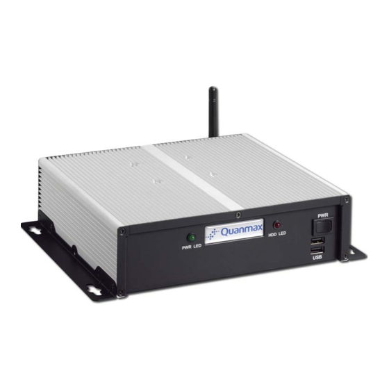
- Page 1 QDSP-2020 Fan-less Box PC with Intel® Atom N270 Processor User’s Guide QDSP-2020 User’s Manual...
- Page 2 © 2008 Quanmax Inc. All rights reserved. The information in this user’s guide is provided for reference only. Quanmax does not assume any liability arising out of the application or use of the information or products described herein. This user’s guide may contain or reference information and products protected by copyrights or patents and does not convey any license under the patent rights of Quanmax, nor the rights of others.
-
Page 3: Table Of Contents
Chapter 3 Getting Started ..................21 Power Connection ................21 Operating System and Drivers............22 Chapter 4 Maintenance and Prevention ..............23 Chapter 5 Interface ....................24 External Connectors ................24 Internal Jumpers ................. 27 QDSP-2020 User’s Manual... -
Page 4: Figures
Figure 8 Wall mount holes spacing ................20 Figure 9 Loosen screws securing DC terminal block and remove from chassis..21 Figure 10 Tighten the terminal block compression clamps, insert into the DC inlet and secure ....................... 21 Figure 11 Jumper Locations..................27 QDSP-2020 User’s Manual... -
Page 5: Tables
Tables Tables Table 1 QDSP-2020 product specifications .............. 15 Table 2 Rear panel connectors description .............. 24 Table 3 USB2.0 Type A connector (USB)..............24 Table 4 10/100/1000 Ethernet RJ-45 Connector (LAN)..........25 Table 5 RS-232/422/485 Port DB-9 Connector (COM1) .......... 25 Table 6 RS-232 Port DB-9 Connector (COM2) ............ -
Page 6: Safety Instructions
Use extreme caution when installing or removing components. Refer to the installation instructions in this user’s guide for precautions and procedures. If you have any questions, please contact Quanmax Post-Sales Technical Support. Access can only be gained by service persons or by users who have been instructed about the reasons for the restrictions applied to the location and about any precautions that shall be taken;... -
Page 7: Preventing Electrostatic Discharge
Static electricity can harm system boards. Perform service at an ESD workstation and follow proper ESD procedure to reduce the risk of damage to components. Quanmax strongly encourages you to follow proper ESD procedure, which can include wrist straps and smocks, when servicing equipment. -
Page 8: Instructions For Lithium Battery
(e.g. to the collecting points for disposal of batteries Voltage Ratings The external power adaptor of the QDSP-2020 has the following voltage ratings: Input: 100-240 VAC Output: 50W, +12VDC, 4.16A max... -
Page 9: Preface
Remove all items from the box. If any items listed on the purchase order are missing, notify Quanmax customer service immediately. Inspect the product for damage. If there is damage, notify Quanmax customer service immediately. Refer to “Warranty Policy” for the return procedure. -
Page 10: Warranty Policy
Quanmax or its authorized agent; or if the failure is caused by accident, acts of God, or other causes beyond the control of Quanmax or the manufacturer. Neglect, misuse, and abuse shall include any installation, operation, or maintenance of the product other than in accordance with the user’s guide. -
Page 11: Maintaining Your Computer
Quanmax. Limitation of Liability In no event shall Quanmax be liable for any defect in hardware, software, loss, or inadequacy of data of any kind, or for any direct, indirect, incidental, or consequential damages in connection with or arising out of the performance or use of any product furnished hereunder. - Page 12 The greatest threats to a system’s supply of power are power loss, power spikes, and power surges caused by electrical storms, which interrupt system operation and/or damage system components. To protect your system, always properly ground power cables and one of the following devices. QDSP-2020 User’s Manual...
- Page 13 Surge protectors should be used with all UPS systems, and the UPS system should be Underwriters Laboratories (UL) safety approved. QDSP-2020 User’s Manual...
-
Page 14: Chapter 1 Introduction
Introduction Overview The QDSP-2020 is a compact Fan-less Box PC ideal for space critical applications. This embedded hardware platform is based on a 3.5” industrial SBC with Intel® Atom N270 Processor, 945GSE/ ICH7-M chipset, and DDR2 533 SO-DIMM up to 2 GB. -
Page 15: Product Specifications
Chapter 1 Product Specifications Table 1 QDSP-2020 product specifications QDSP-2020 User’s Manual... -
Page 16: Mechanical Layout
Chapter 1 Mechanical Layout Figure 1 Mechanical Dimensions QDSP-2020 User’s Manual... -
Page 17: Chapter 2 Assembly/Disassembly
Loosen the 4 roundhead screws from top of the chassis cover. Lift the chassis cover up and off of the chassis base. See figure below for the locations of the internal components of the system. Main Board Figure 2 Mechanical Layout - Internal Components QDSP-2020 User’s Manual... -
Page 18: Installing A Memory Module
Hold the SO-DIMM with its notch aligned with the memory socket of the QDSP-2020 and insert it at a 30-degree angle into the socket. Figure 4 Align the SO-DIMM Memory Module with the onboard socket Fully insert the module into the socket until a “click” is heard. -
Page 19: Figure 5 Fully Insert The So-Dimm Memory Module Into The Onboard Socket
Press down on the SO-DIMM so that the tabs of the socket lock on both sides of the module. Figure 6 Press down on the SO-DIMM Memory Module to lock it in place Replace the chassis bottom cover as described above. QDSP-2020 User’s Manual... -
Page 20: Wall Mounting
The shape of the screw holes allows the QDSP-2020 to be mounted with the Front Panel facing in any orientation, and provides for easy removal of the chassis for repair of maintenance. Use standard M5 screws to mount the QDSP-2020. -
Page 21: Chapter 3 Getting Started
Insert the terminal block into the DC inlet in the chassis and secure by tightening the screws loosened in Step 2. Figure 10 Tighten the terminal block compression clamps, insert into the DC inlet and secure Connect the power distribution to the DC power feed wires. QDSP-2020 User’s Manual... -
Page 22: Operating System And Drivers
You can download the drivers for the product from the Quanmax website at www.quanmax.com and install as instructed there. For other operating systems, please contact Quanmax. -
Page 23: Chapter 4 Maintenance And Prevention
Chapter 4 Chapter 4 Maintenance and Prevention Your QDSP-2020 system requires minimal maintenance and care to keep it operating correctly. Occasionally wipe the system with a soft dry cloth. You should only remove persistent dirt by use of a soft, slightly damp cloth (use only a mild detergent). -
Page 24: Chapter 5 Interface
10/100/1000 Ethernet RJ-45 Connector COM1 RS-232/422/485 Port DB-9 Connector COM2 RS-232 Port DB-9 Connector MS/KB PS/2 KB/MS Mini-DIN Connector DVI-I Connector Audio Audio IN, Audio Out, MIC Table 2 Rear panel connectors description Table 3 USB2.0 Type A connector (USB) QDSP-2020 User’s Manual... -
Page 25: Table 4 10/100/1000 Ethernet Rj-45 Connector (Lan)
RTS, Request to send CTS, Clear to send RI, Ring indicator Table 5 RS-232/422/485 Port DB-9 Connector (COM1) Table 6 RS-232 Port DB-9 Connector (COM2) Signal KBDAT MSDAT KBCLK MSCLK Table 7 PS/2 KB/MS Mini-DIN Connector (MS/KB) QDSP-2020 User’s Manual... -
Page 26: Table 8 Dvi-I Connector (Dvi)
TX6N TX6P TCLP TXLN Table 8 DVI-I Connector (DVI) Connector Function MIC In LINE Out LINE In Table 9 Audio Connectors (Audio) Front I/O Panel USB2.0 Type A Connector Signal Name Signal Name USB1- USB0- USB1+ USB0+ QDSP-2020 User’s Manual... -
Page 27: Internal Jumpers
Clear CMOS Selection Power Mode Selection Backlight & Panel Power Selection Backlight Enable Selection KB/MS Connector Selection USB POWER SELECT Table 10 Jumper List Jumper Status Open Normal Operation (Default) Short Clear CMOS Table 11 JP1 Clear CMOS Selection QDSP-2020 User’s Manual... -
Page 28: Table 12 Jp2 Power Mode Selection
Active High (Default) Active Low Table 14 JP4 Backlight Enable Selection Signal Signal +5VSB KBCLK_SIO KBDAT_ SIO KBCLK_CN7 KBDAT_CN7 MSCLK_SIO MSDAT_SIO MSCLK_CN7 MSDAT_CN7 Table 15 JP5 KB/MS Connector Selection Jumper Status +5VSB (Default) Table 16 JP6 USB POWER SELECT QDSP-2020 User’s Manual...
Need help?
Do you have a question about the QDSP-2020 and is the answer not in the manual?
Questions and answers